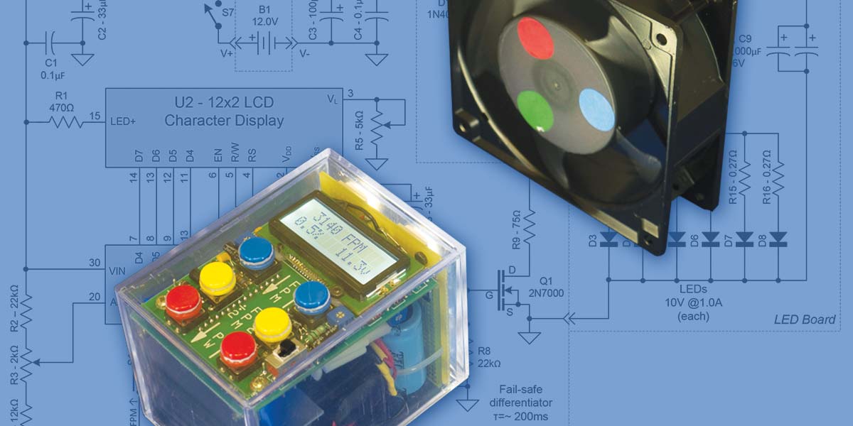
A stroboscope is a flashing light with a variable flash rate. As a calibrated laboratory instrument, it serves two major purposes: by optically "freezing" the motion of a rotating or reciprocating machine, it can determine the operating frequency, and also allow critical examination of these machines while in motion (Figure 1). For us occasional handymen, they are useful in examining power tools like drills, saws, and other tools in the shop, plus around the house for fans, kitchen mixers, blenders, and so forth. They can even be used to freeze the motion of a loudspeaker at a constant tone to look for causes of distortion.
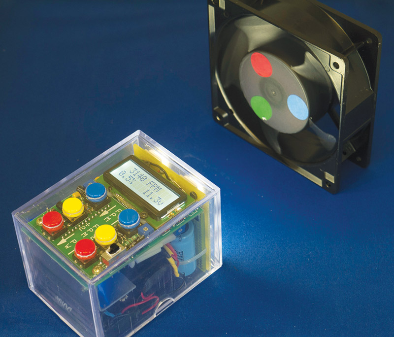
FIGURE 1. The StroboDuino "stopping" a boxer fan with three color dots applied.
Traditional stroboscopes have been expensive enough so that only a few hobbyists or other non-professionals owned them. They used photoflash tubes that — while truly bright — limited their flash rate and required high voltage power supplies. Their heavy power supplies and regular need for AC power compromised their portability.
With the advent of inexpensive digital control circuitry and ever-brighter LEDs, some of these problems have been corrected. It’s now possible to buy a lab-grade LED stroboscope (at a fraction of their previous cost) that is portable and even battery powered. The drawback is that LEDs just aren’t usually as bright as photoflash tubes.
The StroboDuino is a non-professional grade stroboscope that can be built for around $50. It uses some of the latest very bright LEDs that rival photoflash tubes. The low parts count as seen in the schematic (Figure 2) is due to the high level of integration of the Arduino and an integrated LCD module.
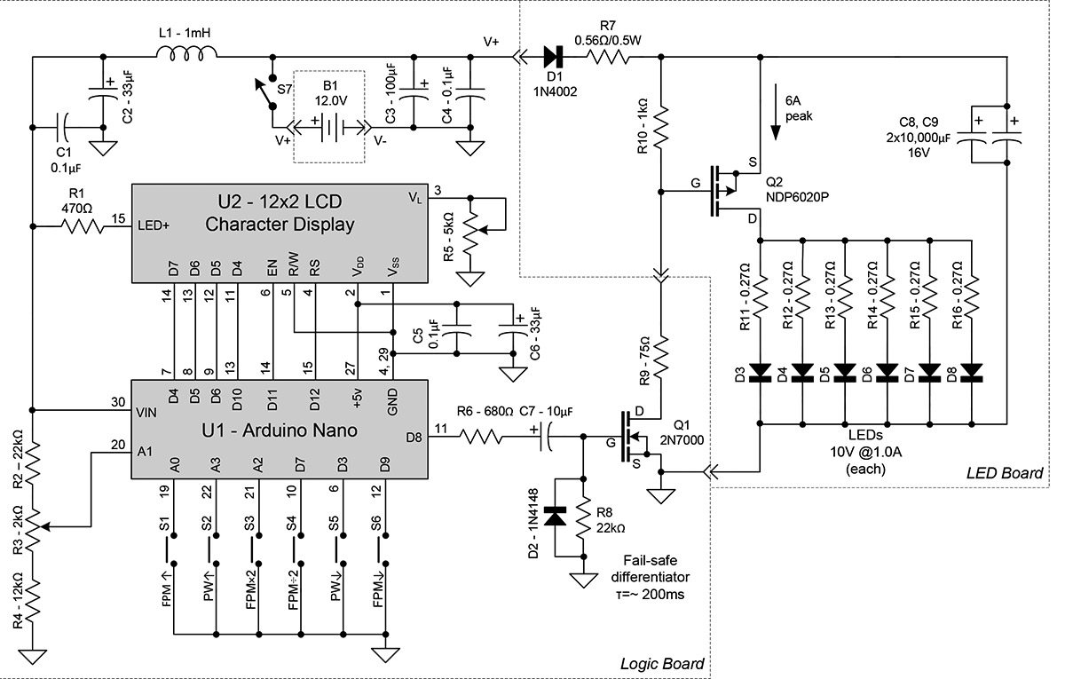
FIGURE 2. StroboDuino schematic.
The Arduino sketch (code) is simple and easy to understand, making this project an ideal first Arduino project. Another benefit of using the Arduino is that it’s crystal controlled, making the StroboDuino accurate to within 0.1%. Once built, it never needs periodic calibrations or other adjustments.
There are a lot of ways to skin this cat. The StroboDuino as described here uses eight AA cells for its 12V power. While rechargeable batteries are a better choice for daily use, and a 12 VDC 2A wall wart is an even better choice if the StroboDuino doesn’t need to work away from AC power, the AA batteries suit better for occasional use. You can use any of these options.
All stroboscopes suffer from sub-harmonic uncertainty. While it’s easy to see that a 12,000 RPM fan will be “frozen” by a flash at 12,000 FPM (flashes per minute), it may not be obvious that it also can be frozen by flashes at 6,000 FPM, and also at any other integer sub-harmonic such as 4,000 FPM, 3,000 FPM, 2,400 FPM, etc. The flashes will occur at the same rotational position, but every second, third, fourth, or fifth rotation. The eye may or may not be able to see any difference.
Harmonics are different. Continuing the example, at 24,000 FPM (x2, second harmonic), the flashes occur twice each rotation. So, the observer will see the fan “stopped” at zero degrees and 180 degrees for a confused appearance. (It is important that the object being viewed looks different at zero and 180 degrees or it can’t be determined that it’s being flashed twice as fast. If the target is symmetrical, the user should place some sort of a contrasting mark on it to make it visually asymmetrical.)
The StroboDuino is no different in its behavior, except that its modern Arduino based hardware allows for the easy implementation of two buttons — the “times 2” and “divide by 2” — that were very difficult to include on old analog stroboscopes. They allow the user to check the exact second and half harmonic instantly. So, if a certain flash rate freezes a machine and 2x that rate causes two superimposed images, you probably have found the correct rotational rate. Spending a little time using these buttons will be clearer than this explanation. The harmonic behavior is illustrated in Figures 3A, 3B, and 3C.
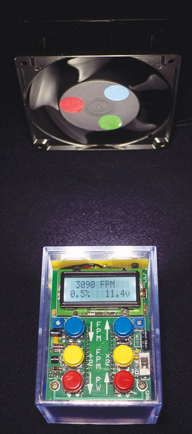
FIGURE 3A. The Arduino "stops" the boxer fan at 3,090 FPM.

FIGURE 3B. At the second harmonic (6,180 FPM), the fan again appears to stop, but the doubling of the color dots gives away that it's the second harmonic.
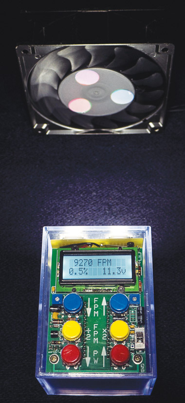
FIGURE 3C. The third harmonic and the color dots overlay each other, adding to gray.
Hardware Design
For this section, refer back to the schematic (Figure 2), Parts List, major components (Figure 4), and LED board (Figure 5).
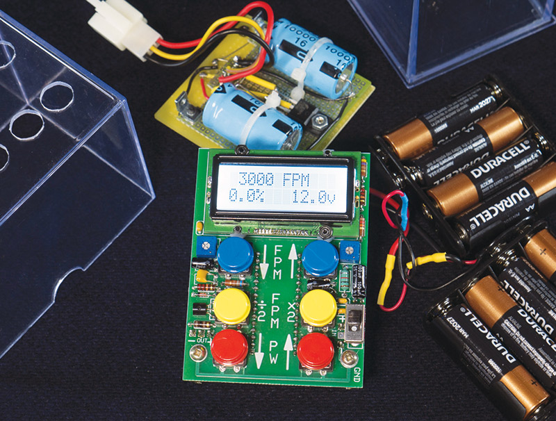
FIGURE 4. Component parts of the StroboDuino as assembled in a card file box.
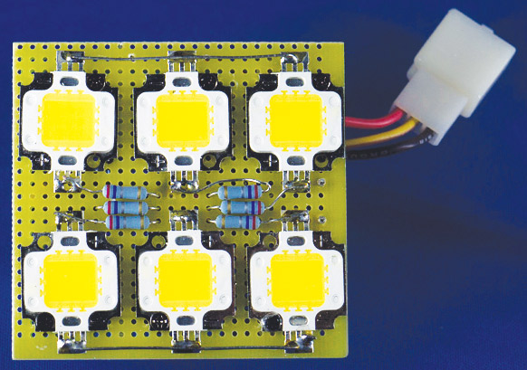
FIGURE 5. The LED board. This shows the 'LED side.'
The schematic is divided into two sections to correspond to the two boards made to fit the enclosure I selected for a prototype (see photos). The larger section is the logic board and the smaller is the LED board. In my prototype, the selected enclosure is a clear heavy plastic box designed to hold 150 baseball cards. Found on eBay for about $2, it fits the parts neatly when the eight AA batteries are used for the power supply. Plus, being transparent, it offers the builder a view of the inner guts while making things fit together.
The two boards and the batteries are (optionally) interconnected with three-pin Molex connectors that I found at MPJA.com. While the selected enclosure was handy during development, the builder should consider other enclosures — especially attractive are cannibalizing a large flashlight’s enclosure — either a pistol-grip or ‘lantern’ type.
If you choose to use a smaller battery or an external wall wart, the reduced volume would allow something smaller, like a cylindrical flashlight. The choice is yours.
The prototype in the photos used a printed wiring board (PWB) for the logic board, and a back-to-back pair of perf boards for the LED board. Again, you can choose this configuration or any other you’re comfortable with. The layout for the PWB was made with ExpressPCB software, and is available in the downloads.
The Logic Board
The logic board is pretty straightforward. The abundance of power supply bypass capacitors and the 1 mH choke (L1) are there to swallow as much of the LED switching transients as possible and isolate them from the Arduino. The Arduino Nano was selected because of its small size. It’s compatible with the more common Uno, but much smaller.
I placed the Arduino on the bottom of the logic board PWB in order to free up real estate on the top of the board for button legends. The Arduino’s pin connections to the pushbuttons and the LCD display are not in numerical order for the convenience of the PWB layout. Since the Arduino provides complete flexibility in assigning pins, swapping pins in the sketch is far easier than moving PWB lands. R5 provides adjustment of U2’s display contrast, while R2-R3-R4 drop the battery voltage to less than 5V so that the Arduino’s analog-to-digital converter (ADC) can sample the battery voltage.
The LCD display chosen is a 12-character x two-line display, using an industry-standard Hitachi CD44780 compatible controller. That makes it compatible with the LCD library in the Arduino IDE (integrated development environment) and a piece of cake to use. The unusual 12x2 format was chosen simply because the 16x2 was too large to fit the selected enclosure. This 12x2 LCD uses aggravatingly small connectors on .05” centers, rather than the 0.1” centers more common on the other displays.
If you choose to use a larger enclosure, the 16x2 display will work fine and will be significantly easier to solder. Adjusting the sketch for the larger display is a snap. R1 supplies current for the LED backlight in the display. Varying its resistance (220Ω-4.7kΩ) will change the backlight brightness; 470Ω provides a comfortable brightness in my brightly-lit lab.
Q1 is a buffer amplifier to isolate the moderate current requirement of the LED board from the Arduino’s small signal. The polarity is as follows: When the output of the Arduino (D8) is high, Q1 switches on; the drain of Q1 is pulled low, which pulls Q2’s gate low on the LED board, and turns the LEDs on. The differentiator formed by R6, C7, R8, and D2 is a fail-safe circuit, assuring that if the Arduino gets stuck with its output high, the drive to Q1 will drain away in about 220 ms and the LEDs will turn off. (This has proven to be unnecessary in practice, but it’s cheap insurance.)
The LED Board
The LED board is where the high current action is. Its heart is the big storage capacitor (C8+C9), Q2, and D3-D8. Each of these LEDs is rated at 1,000 lumens, 10 volts, and one amp. All six fire at once, drawing a total of 6A to produce a whopping 6,000 lumens. The large capacitance of C8+C9 provides energy storage to supply the LED’s 6A demand without subjecting the batteries to this high draw. The StroboDuino’s flash is limited to 10% duty cycle, meaning that the batteries will see a maximum average demand of about 600 mA.
In practice, the flash duty cycle is usually kept at 0.5%, which drops the average battery demand to only about 30 mA — a very comfortable level for alkaline batteries. (Interpolating the graph on Duracell’s AA datasheet, the batteries should be able to source 30 mA constantly for about 20 hours before dropping to 11.2 volts.) Limiting the LED duty cycle also limits heat accumulation, allowing the LEDs to be used safely without heatsinks. R11-R16 represents equalizing resistors so that each LED will see the approximate same energy.
Q2 (an NDP6020P) is a premium switching P-channel MOSFET optimized for extremely low ‘on’ resistance of only about 0.05Ω. While it’s important to keep this resistance low (it’s a pure loss), the loss is small compared to the equalizing resistors. Other (i.e., cheaper) P-channel MOSFETs can be substituted. Even bipolar NPN power transistors with slightly more voltage drop can be substituted.
D1 acts as a check valve so that C8+C9 won’t reverse-power the logic board when it’s turned off, and also to drop the 12V battery voltage to something around 11.4 volts for C8+C9. When the drops of R11- R16 and Q2 are subtracted from the 11.4 volts, the LEDs are within their maximum voltage of 11.0 volts.
The chosen LEDs are really bright, but expensive. You can substitute less expensive LEDs as long as the 11 volt supply voltage is taken into consideration in your design. In most uses, the prescribed LEDs are overkill, and acceptable performance can be had from an array of smaller LEDs.
Software — the Arduino Sketch
This section will follow the flowchart (Chart 1) for the StroboDuino sketch which, in turn, refers to the StroboDuino sketch downloadable at the article link.
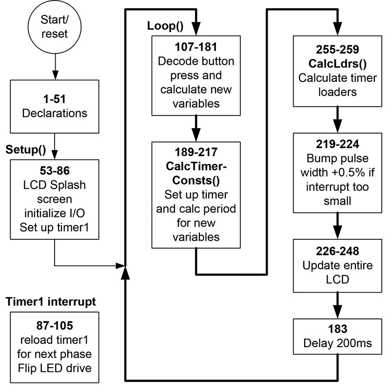
CHART 1. StroboDuino flowchart.
Architecture
Before we look at the details in the code shown in Listing 1, let’s do a high level overview. In operation, the operator selects flash rate with the FPM↑, FPM↓, FPM÷2, and FPMx2 buttons. The corresponding flash rate (in FPM) is always shown on the LCD display. The FPM↑ and FPM↓ buttons start off incrementing (or decrementing) by one; then, they actually accelerate as long as they are held down. The operator will need to become adept at ‘letting off’ to slow the rate of change.
The FPM÷2 and FPMx2 buttons are debounced for one shot per button press. The bottom two buttons (with red caps in the prototype) are PW↑ and PW↓ for adjusting the pulse width percentage from 0 to 10% in 0.5% increments.
The StroboDuino uses the Arduino’s 16-bit Timer1 for its LED timing. The Timer1 loaders are derived from the inputted FPM variable and the pulse width (pw) variable; refer to Figure 6. The ‘period’ in this graphic is the timer loader variable calculated based on the FPM in the display.
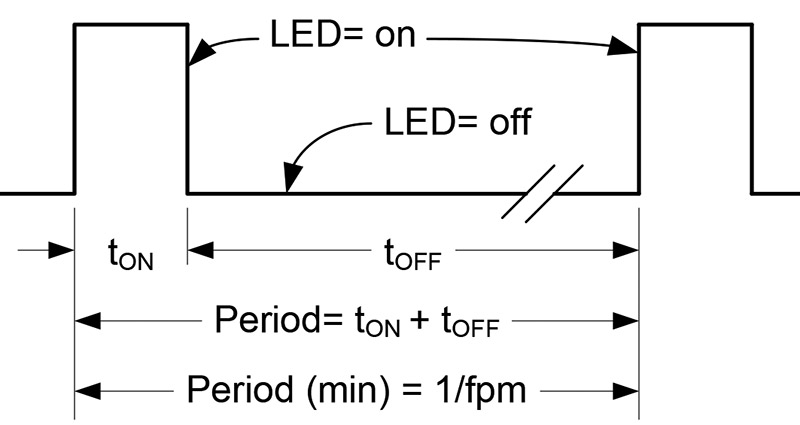
FIGURE 6. LED flash timing.
That number is split according to the pw percentage, so that we have two loaders: one for the on time (rLoaderH), and one for the off time (rLoaderL). On each timer interrupt (each transition in Figure 6), the appropriate loader is written into the Timer1 register for the next phase. Simple as that.
Looking at Table 1, we see how Timer1’s registers are used.
| Band |
Prescaler |
Low FPM |
Divisor |
Resolution
FPM/tick |
|
High FPM |
Divisor |
Resolution
FPM/tick |
Max roundoff
error percentage |
| 1 |
1024 |
15 |
63085.94 |
0.0002378 |
to |
99 |
9469.697 |
0.0104544 |
0.0106% |
| 2 |
256 |
100 |
37851.56 |
0.0026419 |
to |
299 |
12541.81 |
0.02384027 |
0.0080% |
| 3 |
64 |
300 |
50468.75 |
0.0059443 |
to |
1999 |
7503.752 |
0.26640007 |
0.0133% |
| 4 |
8 |
2000 |
60562.5 |
0.0330237 |
to |
14648 |
8192.245 |
1.78803253 |
0.0122% |
| 5 |
1 |
14649 |
65533.48 |
0.2235346 |
to |
399000 |
2406.015 |
165.834375 |
0.0416% |
TABLE 1. StroboDuino Timer1 interrupt operation.
Since this is only a 16-bit timer, we have to also use the Timer1 prescaler in order to cover the StroboDuino’s extraordinary range of 15-399,000 FPM. This table also shows the calculated resolutions for each band, and the maximum round-off error contributed by the timer accuracy. While the error is acceptable for physical moving objects (less than 0.1%), the very high end of bands 4 and 5 have some interesting behavior. As the FPM nears its high limit in band 5, the display will show each FPM integer up to 399,000 FPM. The accuracy of the timer at this limit is only 166 FPM per timer tick. So, at the limit (399,000 FPM), you can change the displayed FPM by as much as 165 counts before the actual flash rate changes. As this is well within the 0.1% allowable error, it’s tolerable, if perhaps unexpected. It’s all due to the resolution of the Arduino’s Timer1.
Using the Timer1 interrupt also causes another problem as the frequency increases. If the pulse width is short enough, as the flash rate is increased, at some point the pulse itself becomes too brief for the interrupt process to handle. The timer will time out while still in the interrupt routine and a new interrupt will occur. So, the process ends up chasing its tail. This happens at 20,338 FPM when the PW is 0.5% (pulse width is a scant 147 µs).
To fix this, the Arduino will lengthen the pulse width as necessary (in normal 0.5% increments) to avoid interrupt misoperation. So, when transitioning from 20,338 FPM to 20,339 FPM, the StroboDuino will bump its PW from 0.5% to 1.0% automatically.
To show that it’s done this, the LCD places an asterisk next to the changed pulse rate, so the operator can make note and manually change it when the FPM is reduced. The StroboDuino will continue to bump the pulse width as necessary to insure proper operation, right up to the maximum of 399,000 FPM where the pulse width must be at its maximum (10%) to avoid misoperation.
Code Description
Lines 1-51: Declarations
These declarations include pin assignments, storage for the sketch’s variables, and two constants. As previously referenced, the pin assignments in the Arduino are simple and easily changed to accommodate your physical layout.
Lines 6-8 are all the initialization the LCD needs; line 6 includes the LCD library; line 7 (a comment) shows the pin assignment format; and line 8 makes the actual pin assignments based on the format in line 7. Line 29 declares the Arduino crystal frequency in Hz. Since the StroboDuino timing is based on flashes per minute — not per second — the base timing unit in line 30 is crystal frequency in cycles per minute: rXtal.
Lines 53-86: Setup() — LCD Splash Screen, Initialize I/O, Set Up Timer1
The ‘splash screen’ is what shows on the LCD before the operator starts operation by pressing one of the red buttons. The builder can display anything here, such as his/her name, the name of the device, etc.
It has no effect on device operation. Lines 63-69 configure the port lines previously declared.
Lines 73-84 set up Timer1 for interrupt operation and for a dummy starting value until the operator enters real parameters.
Lines 107-181: Executing the Loop()
This first function of the loop() section is to read the operator’s button pushes and set up the StroboDuino’s internal registers to reflect that input. The loop repeats every 200 ms (1/5 second) as directed in line 183.
111 - 114: If both PW↓ and PW↑ are pressed simultaneously, the StroboDuino selects PW = 0.0%.
115 - 122: If PW↑ is pressed, add 0.5% to the pulse width register.
123 - 130: If PW↓ is pressed, subtract 0.5% from the pulse width register.
131 - 142: If FPM↑ is pressed, the FPM register is incremented, and increments again every 1/5 second as long as the button is held down, as long as the maximum of 399,000 FPM isn’t exceeded.
If after five counts (one second), the button is still pressed, it begins to increment by five on each 1/5 second tick, as long as the maximum of 399,000 FPM isn’t exceeded.
- After 10 counts (two seconds), it increments by 10 on each tick until 399,000.
- After 15 counts (three seconds), it increments by 100 as above.
- After 20 counts (four seconds), it increments by 200 as above.
- After 40 counts (eight seconds), it increments by 1,000 as above.
- After 60 counts (12 seconds), it increments by 10,000 as above.
143-154: The exact same behavior as FPM↑ above is duplicated for FPM↓, except the FPM register is decremented (in the same progression) down to a minimum FPM of 15.
The acceleration behavior of FPM↑ and FPM↓ is very easy to change if you want to modify it. Just change the self-explanatory constants in lines 131-154.
155-164: If FPMx2 is pressed and there’s room beneath 399,000, double the FPM. This button will only operate once on each button push and release. This is controlled by skipx2.
165-174: If FPM÷2 is pressed and there’s room above 15 FPM, halve the FPM. Button behavior is the same as the FPMx2 button controlled by skipby2.
182: Function CalcTimerConsts() (below) is called.
183: Processing delays 200 ms (variable fld), then loops back to line 107.
Lines 189-217: Function CalcTimerConsts()
This section uses the inputted data of desired flashes per minute and desired pulse width to calculate Timer1 constants to be loaded on the next Timer1 interrupt. The code first tests the FPM register, sets the timer prescaler, and calculates the total interrupt loader for the entire period (on time plus off time). Refer again to Table 1.
- If FPM ≥ 14,649, prescaler = 0 and period = rXtal/FPM.
- If FPM ≥ 2,000, prescaler = 8 and period = rXtal/(8*FPM).
- If FPM ≥ 300, prescaler = 64 and period = rXtal/(64*FPM).
- If FPM ≥ 100, prescaler = 256 and period = rXtal/(256*FPM).
- If FPM < 100, prescaler = 1024 and period = rXtal/(1024*FPM).
Then, call the function CalcLdrs (described shortly) to calculate the timer loaders.
Lines 219-224: Bump Pulse Width if Interrupt is Too Fast
As referenced above, this piece of code tests the on time pulse width. If the timing is too fast for the interrupt process to function reliably, it automatically increases the pulse width (in 0.5% increments) until the calculated interrupt time is within limits.
Using my Arduino Nano 3.0 and the Arduino IDE, the threshold for interrupt pulse width is 236 cycles, as shown in line 219.
If your setup is different and flashes erratically, try increasing this number to compensate. It’s not a big deal — just increase the number in line 219 and recompile until it behaves.
Lines 226-248: Update the LCD
No magic here. The top LCD line shows the FPM, and the bottom line shows the pulse width percentage and the battery voltage. Additionally, if the code has automatically bumped the pulse width to overcome the short interrupt problem (see above, lines 219-224), splatOn will have been set. This routine places an asterisk next to the pulse width.
Lines 255-259: CalcLdrs()
This function calculates the timer loaders for each phase, based on the ‘period’ variable calculated in CalcTimerConsts() (mentioned previously) and the pulse width percentage. The algorithms are:
Pulse high duration (rLoaderH)= (pulse width percentage) * period
Pulse low duration (rLoaderL)= 0.999*(1- pulse width percentage) * period
The .999 factor shortens the off time by a very small amount in order to compensate for the occasional timer ticks lost during the interrupt process. Its value was determined experimentally.
Lines 87-105: Timer1 Interrupt
This section tests the output phase by looking at the output pin, then reloads Timer1 with the loader for the opposite phase and flips the phase of the output pin.
Assembly
My prototype can be easily duplicated or you can build the StroboDuino into a different enclosure using different LEDs, a different power source, different LCD display, or even a different Arduino. There is nothing at all critical about the assembly, and the sketch will work on other Arduinos.
As mentioned previously, mine is built of clear plastic so the fit of all the components could be seen. Let your imagination go, or just build it into a baseball card box like I did.
If you use the 12x2 display called out in the Parts List, the tiny 0.05” spacing on the connector is hard to solder manually. Using a PWB makes it a little easier, but not by much. If you decide to use a different display with the conventional 0.1” connector spacing, using standard perf boards at a much lower cost makes sense. Your call! The PWB artwork is also available in the downloads section.
There are two adjustments to be made at final assembly time. First, R5 should be adjusted for the most pleasing display appearance to you. Then, the battery voltage must be calibrated.
With a new set of batteries installed, set R3 so that the LCD displays “12V.” That’s it. You’ll be able to watch the effects of high pulse widths and decreasing battery voltage with age and use.
Operation
At this point, there’s not a lot to add. However, the pulse width deserves a little discussion.
The LEDs are bright enough so that they will normally overcome normal room illumination and be sufficiently bright even at the narrowest PW of 0.5%. If the brightness isn’t sufficient, you can increase the pulse width and get more illumination.
However, as the PW increases, resolution decreases. The fastest PW (0.5%) means the LEDs are on for 0.5% of the time.
When a rotating device is being visually stopped by the Stroboduino, a PW of 0.5% means that the LEDs are on for 360° x 0.5%, or 1.8° of arc. This presents a pretty sharp image.
However, increasing the pulse width to, say, 5%, means the LEDs are on for about 18° of arc, causing a decidedly smeared appearance. You can decide how much PW you need, and how much smearing you can tolerate in the situations you encounter.
A Final Note
The StroboDuino times with the flashes per minute rather than the SI unit of Hz. This is because — conventionally — motors are rated in RPM, and FPM and RPM correspond 1:1. The StroboDuino takes it a step further with its display and all its internal computations based on FPM. If you need to convert back to Hz, 1 Hz equals 60 RPM (or FPM), so conversion to Hz only involves dividing FPM by 60.
A footnote to this is that if you choose to use a 16x2 LCD display, you’ll have space to put Hz on the display in addition to FPM [lcd.print(String(fpm/60, DEC));].
Now, go freeze something! NV
Parts List
| Designator |
Description |
Qty |
Source |
Part Number |
| B1 |
1.5V AA alkaline battery |
8 |
Costco (local) |
Duracell AA |
| C1, C4, C5 |
.1 μF/25V ceramic cap |
3 |
Mouser.com |
21RZ310-RC |
| C2, C6 |
33 μF/16V electrolytic |
2 |
Mouser.com |
USR1C330MDD |
| C3 |
100 μF/16V electrolytic |
1 |
Mouser.com |
598-107CKS016M |
| C7 |
10 μF/16V electrolytic |
1 |
Mouser.com |
598-106RSS016M |
| C8, C9 |
10,000 μF/16V electrolytic |
2 |
amazing1-nh (eBay) |
2x10000uF/16V |
| D1 |
1N4002 |
1 |
Mouser.com |
833-1N4002-TP |
| D2 |
1N4148 |
1 |
Mouser.com |
583-1N4148-T |
| D3-D8 |
10W, 1A, 10V, 1,000 Lumen LED |
6 |
MPJA.com |
31325 OP |
| L1 |
1 mH, 60 mA choke |
1 |
Mouser.com |
542-78F102J-RC |
| Q1 |
2N7000 |
1 |
Mouser.com |
821-TSM2N7000KC821-T |
| Q2 |
NDP6020P |
1 |
Mouser.com |
512-NDP6020P |
| R1 |
470Ω, 1/4W resistor |
1 |
Mouser.com |
660-MF1/4LCT52R471J |
| R2, R8 |
22kΩ, 1/4W resistor |
2 |
Mouser.com |
660-MF1/4LCT52R223J |
| R3 |
2kΩ, mini trim pot |
1 |
Mouser.com |
652-3306K-1-202 |
| R4 |
12kΩ, 1/4W resistor |
1 |
Mouser.com |
660-MF1/4LCT52R123J |
| R5 |
5kΩ, mini trim pot |
1 |
Mouser.com |
652-3306K-1-502 |
| R6 |
680Ω, 1/4W resistor |
1 |
Mouser.com |
660-MF1/4LCT52R681J |
| R7 |
0.56Ω, 1/2W resistor |
1 |
Mouser.com |
279-LR1LJR56 |
| R9 |
75Ω, 1/4W resistor |
1 |
Mouser.com |
660-MF1/4LCT52R750J |
| R10 |
1kΩ, 1/4W resistor |
1 |
Mouser.com |
660-MF1/4LCT52R102J |
| R11-R16 |
0.27Ω, 1/2W resistor |
6 |
Mouser.com |
660-MOX1/2CT52AR27 |
| S1-S6 |
SPST pushbutton switch |
2 |
MPJA.com |
30039 SW |
| S7 |
SPDT slide switch |
1 |
Mouser.com |
633-CS12ANW03 |
| U1 |
Arduino Nano clone |
1 |
MPJA.com |
31354 MP |
| U2 |
5V, 2x12 LCD character display |
1 |
EastRising (eBay) |
ERM1202FS-1 |
| BH1 |
4xAA battery holder |
2 |
MPJA.com |
32527 BH |
Listing 1
/*StroboDuino sketch 170610 for 12x2 digit display 1 on PWB 170423
2 schematic 170530
3 Mike Huddleston
4 */
5
6 #include <LiquidCrystal.h> // include LCD library
7 // format (rs, en, d4, d5, d6, d7) map of LCD assignments
8 LiquidCrystal lcd(12, 11, 10, 6, 5, 4); // assign Arduino I/O to LCD
9
10 // declare digital I/O
11
12 #define pwDnPin 3 // pulse width 'down' button
13 #define by2Pin 7 // frequency (FPM) divide-by-2 button
14 #define ledPin 8 // output to LED drive (flash)
15 #define dnPin 9 // frequency (FPM) 'down' button
16
17 // declare analog input
18
19 #define vBat A1 // battery check (analog input)
20
21 // analog inputs repurposed as digital inputs from switches
22
23 #define upPin A0 // frequency (FPM) 'up' button
24 #define x2Pin A2 // frequency (FPM) multiply-by-2 button
25 #define pwUpPin A3 // pulse width 'up' button
26
27 // constant declarations for calculating timer loaders
28
29 long fXtal = 16.0E6; // crystal frequency in Hz
30 long rXtal = 60.0*fXtal; // crystal frequency in FPM
31
32 // variable declarations
33
34 long fpm = 3000; // starting flash rate
35 float period; // intermediate result, timer loader for total period
36 unsigned long rLoaderH; // register loader for OCR1A high phase
37 unsigned long rLoaderL; // register loader for OCR1A low phase
38 float percentage = 0.0; // default pulse width percentage
39 int fld = 200; // foreground loop delay = 200ms
40
41 int upCtr = 0; // switch debouncing counters
42 int dnCtr = 0;
43 int x2Ctr = 0;
44 int by2Ctr = 0;
45 int skipx2 = 0;
46 int skipby2 = 0;
47
48 int onDisplay = 0; // suppress LCD update until first red key push
49 int splatOn; // displays splat if pulse width automatically extended
50
51 //**********************************************
52
53 void setup()
54 {
55 lcd.begin(12,2); // LCD initial display
56 lcd.clear();
57 lcd.print ("StroboDuino*");
58 lcd.setCursor (0,1);
59 lcd.print ("Push red key");
60
61 // initialize I/O pins
62
63 pinMode(ledPin, OUTPUT);
64 pinMode(upPin, INPUT_PULLUP); Assign button pins as inputs with pullups
65 pinMode(pwUpPin, INPUT_PULLUP);
66 pinMode(x2Pin, INPUT_PULLUP);
67 pinMode(by2Pin, INPUT_PULLUP);
68 pinMode(pwDnPin, INPUT_PULLUP);
69 pinMode(dnPin, INPUT_PULLUP);
70
71 digitalWrite (ledPin, LOW); // initialize pulse output to 'off' state
72
73 // initialize Timer 1 (16-bit timer with no sharing)
74
75 noInterrupts(); // disable interrupts
76
77 TCCR1A = 0; // normal timer 1 operation
78 TCNT1 = 0;
79
80 OCR1A = 100;
// Dummy first interrupt; then calculated
81 TCCR1B = B00001011; // turn on WGM12, CS11, CS10 // (divide 16MHz by 64)
82 TIMSK1 = B00000010; // enable timer compare interrupt
83
84 interrupts(); // re-enable interrupts
85 }
86 //**********************************************
87
88 //timer 1 interrupt service routine
89
90 ISR(TIMER1_COMPA_vect)
91 {
92 // load appropriate delay for phase and invert output phase
93
94 if (digitalRead(ledPin) == LOW) // if LED is off, load 'on' timer loader
95 {
96 OCR1A = rLoaderH;
97 digitalWrite (ledPin, HIGH); // and turn LED on
98 }
99 else
100 {
101 OCR1A = rLoaderL; // load 'off' timer loader
102 digitalWrite (ledPin, LOW); // and turn LED off
103 }
104 }
105 //*********************************************
106
107 void loop()
108 {
109 // decode and execute button pushes
110
111 if (digitalRead(pwUpPin) == LOW && digitalRead(pwDnPin) == LOW)
112 {
113 percentage = 0.0; // if both PW buttons are pushed, make PW=0
114 }
115 else if (digitalRead(pwUpPin) == LOW) // if pulse width up button is pushed
116 {
117 bumpPW(); // add 0.5 to pulse width
118 splatOn = 0;
119 upCtr = 0;
120 dnCtr = 0;
121 onDisplay = 1;
122 }
123 else if (digitalRead(pwDnPin) == LOW) // if pulse width down button
124 {
125 if (percentage > 0.0) percentage = percentage - 0.5;
126 upCtr = 0;
127 dnCtr = 0;
128 splatOn = 0;
129 onDisplay = 1;
130 }
131 else if (digitalRead(upPin) == LOW) // if FPM up button
132 {
133 upCtr += 1;
134 if (upCtr > 60 && fpm < 380000) fpm += 10000;
else if (upCtr >40 && fpm < 398000)
135 fpm += 1000;
136 else if (upCtr >20 && fpm < 398800) fpm += 200;
137 else if (upCtr >15 && fpm < 398900) fpm += 100;
138 else if (upCtr >10 && fpm < 398990) fpm += 10;
139 else if (upCtr > 5 && fpm < 398995) fpm += 5;
140 else if (fpm < 399000) fpm = fpm + 1;
141 dnCtr = 0;
142 }
143 else if (digitalRead(dnPin) == LOW) // if FPM down button
144 {
145 dnCtr += 1;
146 if (dnCtr > 60 && fpm > 10015) fpm -= 10000;
147 else if (dnCtr > 40 && fpm > 1015) fpm -= 1000;
148 else if (dnCtr > 20 && fpm > 215) fpm -= 200;
149 else if (dnCtr > 15 && fpm > 115) fpm -= 100;
150 else if (dnCtr > 10 && fpm > 25) fpm -= 10;
151 else if (dnCtr > 5 && fpm > 20) fpm -= 5;
152 else if (fpm > 15) fpm -= 1;
153 upCtr = 0;
154 }
155 else if (digitalRead(x2Pin) == LOW && fpm < 199501) // if FPM*2 button
156 {
157 if (skipx2 == 0)
158 {
159 fpm = 2*fpm;
160 dnCtr = 0;
161 upCtr = 0;
162 skipx2 = 1;
163 }
164 }
165 else if (digitalRead(by2Pin) == LOW && fpm > 30) // if FPM/2 button
166 {
167 if (skipby2 == 0)
168 {
169 fpm = fpm/2;
170 dnCtr = 0;
171 upCtr = 0;
172 skipby2 = 1;
173 }
174 }
175 else // no button
176 {
177 dnCtr = 0;
178 upCtr = 0;
179 skipx2 = 0;
180 skipby2 = 0;
181 }
182 CalcTimerConsts(); // calculate timer loaders // based on new inputs
183 delay(fld); // delay and loop back
184 }
185 //*********************************************
186
187 //Functions
188
189 void CalcTimerConsts ()
190 {
191 if (fpm >= 14649.0)
192 {
193 TCCR1B = B00001001;
// turn on WGM12,CS10 (straight 16MHz, no prescale)
194 period = rXtal / fpm; //
195 }
196 else if (fpm >= 2000.0)
197 {
198 TCCR1B = B00001010;
// turn on WGM12,CS11 (divide 16MHz xtal by 8)
199 period = (rXtal/8) / fpm; //
200 }
201 else if (fpm >= 300.0)
202 {
203 TCCR1B = B00001011;
// turn on WGM12, CS11, CS10 (divide 16MHz xtal by 64)
204 period = (rXtal/64) / fpm; //
205 }
206 else if (fpm >= 100.0)
207 {
208 TCCR1B = B00001100;
// turn on WGM12, CS12 (divide 16MHz xtal
// by 256)
209 period = (rXtal/256) / fpm; //
210 }
211 else
212 {
213 TCCR1B = B00001101;
// turn on WGM12, CS10, CS12 (divide 16MHz
// xtal by 1024)
214 period = (rXtal/1024) / fpm; //
215 }
216
217 calcLdrs(); // calculate timer loaders based on new period calc
218
219 while (percentage >0.0 && TCCR1B == B00001001 && rLoaderH < 236)
220 {
221 bumpPW (); // if timer loader is too small, bump PW
222 calcLdrs();
223 splatOn = 1; // and display asterisk
224 }
225
226 if (onDisplay != 0)
// change display only if red button has
// been pushed
227 {
228 lcd.clear(); // update LCD
229 lcd.setCursor (1,0);
230 lcd.print (String(fpm, DEC));// print FPM
231 lcd.print (" FPM");
232
233 lcd.setCursor (0,1); // print pulse width percentage on second line
234 lcd.print (percentage);
235 lcd.setCursor (3,1);
236 lcd.print ("%");
237 if(splatOn == 1)
238 {
239 lcd.print("*");
240 }
241 else lcd.print (" ");
242
243 lcd.setCursor (7,1);
244 lcd.print (float(analogRead(vBat)/75.0)); // print voltage
245 lcd.setCursor (11,1);
246 lcd.print( "v ");
247 }
248 }
249
250 void bumpPW () // increase pulse width by 0.5%
251 {
252 if (percentage < 10.0) percentage = percentage + 0.5;
253 }
254
255 void calcLdrs () // calc timer loaders from 'period' and 'percentage'
256 {
257 rLoaderH = ((percentage / 100.0) * period);
// calc timer loader for ON phase
258 rLoaderL = .999*((1.0 - (percentage / 100.0)) * period);
// calc tmr ldr for OFF phase
259 }
Downloads
What’s in the zip?
Source Code
PCB File