I use LCD displays in almost every project. They are perfect for displaying data about voltage, current, time, frequency, wind speed, rainfall, etc. However, in this modern age of steampunk, I stumbled on something much cooler.
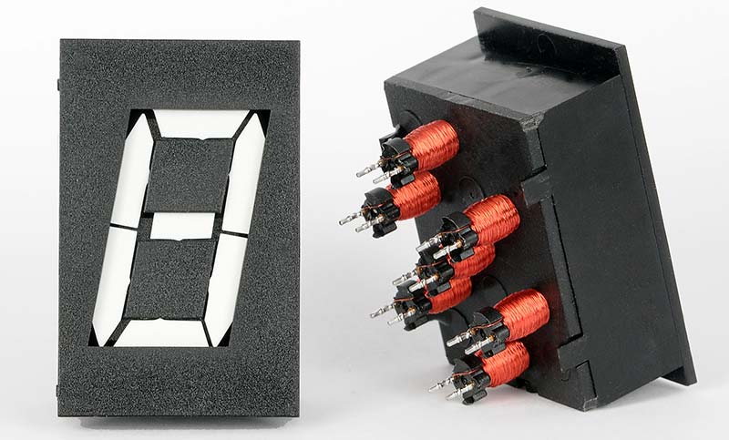
I found a number of vendors on eBay who were selling surplus 1” high seven-segment electromechanical displays (EMDs) that go clickity click (see Figure 1).
FIGURE 1. The seven electromagnetic coils are driven by 25 ms bipolar pulses that flip the segments on or off.
The segments appear and disappear in the blink of an eye when the tiny coils are pulsed. They aren’t quite as fast as LCDs, but they can add a whole new dimension to your project: sound!
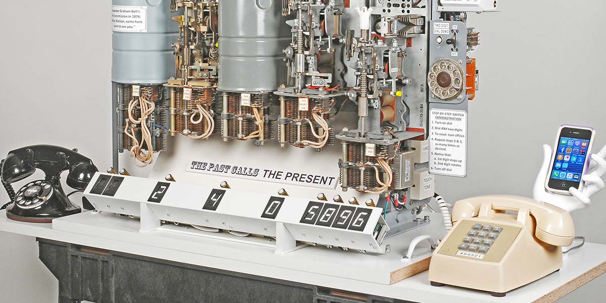
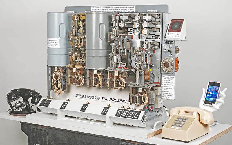
Many months ago, I embarked on an ambitious project that featured five 1941 vintage rotary telephone step-by-step (SXS) switches. I thought these little EMDs would be the perfect match to display the dialed digits; refer to Figure 2. So, I ordered a dozen from a guy in Hungary and the rest is history. You can see nine of them mounted in a line under the SXS switches.
FIGURE 2. My step-by-step vintage 1941 telephone switch demonstrator uses nine displays to show the numbers dialed.
Reinventing the Wheel
The displays didn’t come with drivers and I couldn’t find a commercial source. I saw a reference to a 40-pin FP2800A decoder/driver IC but it was no longer available, so I decided to build my own. Maybe I missed something, but it wouldn’t be the first time I set about reinventing the wheel.
I learned a few things along the way, and it was a rewarding experience to design and build the PCB (printed circuit board) drivers using tiny SMD components. Perhaps you can find an application for these funky little displays and have as much fun building with them as I did.
The Requirements
My requirements were simple. Each display had to be a stand-alone unit with its own driver. I needed them to be physically located at different positions in the telephone project, which didn’t lend itself to grouping them in most cases. So, I made each one an independent unit with three stacked boards as shown in Figure 3.
FIGURE 3. The stack of boards includes an ATtiny2313 µC and four TB6612 dual motor drivers to decode and flip segments A-G.
They also had to be front-mountable in rectangular holes in a panel — much like mounting LCD displays.
Lastly, they had to accept two types of inputs: a totalizing pulse input (1-10 pulses) from a relay contact or telephone dial; and a daisy-chained SPI data/clock input that was addressable from a host microcontroller.
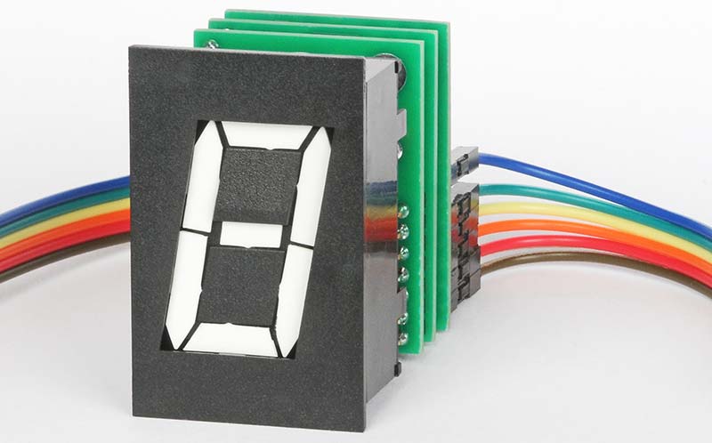
The plan was to build a total of nine daisy-chained displays for the telephone project. Figure 4 shows the completed three-board assembly, with six daisy-chained wires going in and out.
FIGURE 4. Multiple displays can be daisy-chained together to respond to SPI generated addresses and digits.
Let’s Get Started
Let's take a look at how I designed and built the drivers and some of the problems I encountered.
The first task was locating a suitable bi-directional driver for each segment, like an H-bridge. I found references to a 40-pin FP2800A IC that could drive multiple digits, but I never could find a source. Besides, I really wanted something smaller since I wanted the digits to be independent and compact.
If the displays were to be used for something else like a clock, they could all be mounted on a longer PCB and there would be plenty of room for an FP2800A (if you can find one).
After more research, I finally settled on the Toshiba TB6612 which contains two motor drivers and is normally used to control small DC motors. However, I blanched when I saw it only came in a tiny SSOP package. I had used many SMD parts in the past but never any with a 0.025” pitch. All I could picture was a mess of solder bridges!
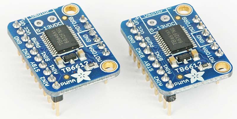
Luckily, Adafruit carried TB6612 breakout boards for $4.95 each, which I could use to breadboard up the circuit. Figure 5 shows two of the four boards I acquired.
FIGURE 5.I used four of the Adafruit TB6612 motor driver boards for a breadboard before committing to a PCB.
Breadboard Stage
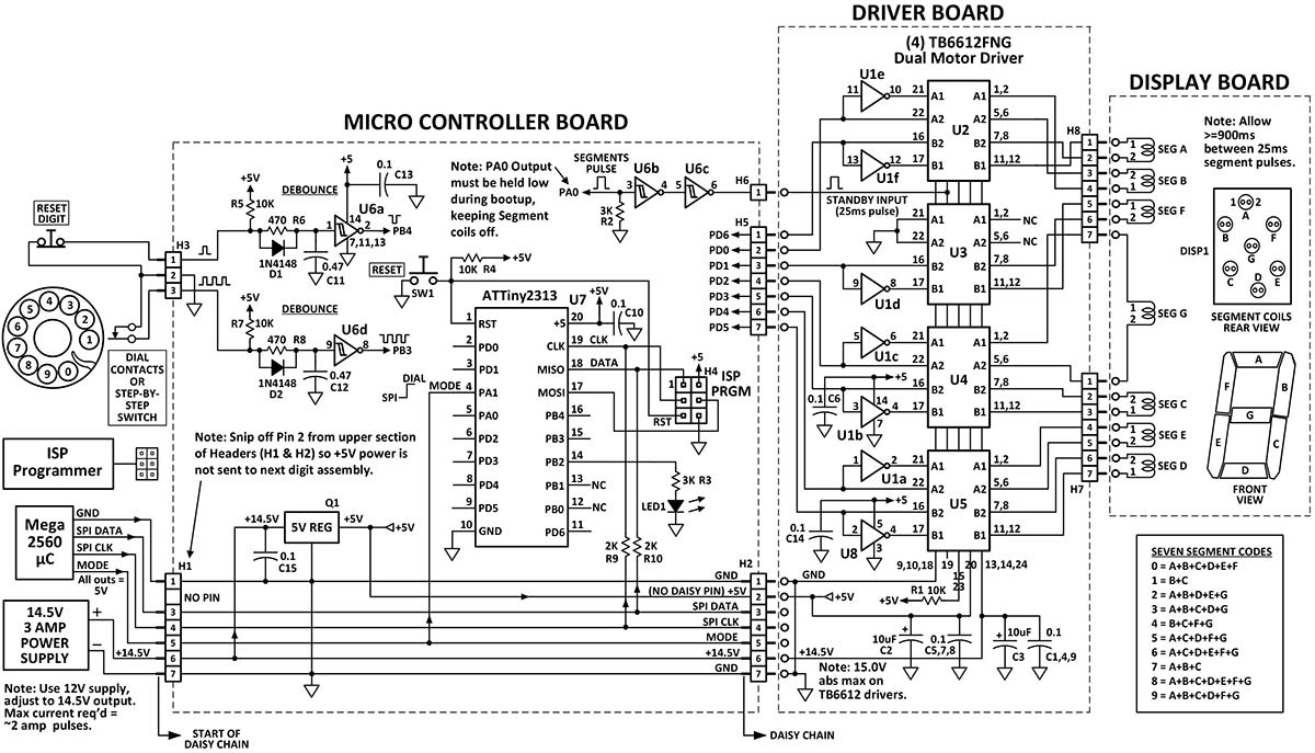
I like to start with a breadboard before I commit to a PCB because of several painful experiences in the past. The breadboard consisted of four TB6612s, some inverters, and an ATtiny AVR chip to do the decoding and pulsing. Figure 6 is the schematic of the final unit, but the breadboard was very similar.
FIGURE 6. The schematic shows that each assembly can accept pulses from an NC contact or one byte (addr+data) via the daisy-chained SPI lines.
Amazingly, it worked the first time. I had not mis-wired a single segment. However, just as I was congratulating myself, I said “What’s that smell? Something is burning!
The spec sheet for the displays emphasized that the segments should not be pulsed more frequently than 900 ms because the coils would overheat. I had programmed the Tiny to wait the correct interval but as I moved several wires on the breadboard (without turning off the power?), I inadvertently let the TB6612 standby pins float high for a minute or so. Several coils got really hot and almost burned out.
From then on, I pulled the standby line to ground with a 3K resistor and kept it low, except during the 25 ms pulses. Problem solved. Whew!
(BTW, in my video on YouTube I mentioned applying a 250 ms pulse. Not so! 25 ms is the correct duration.)
Counting Dial Pulses and SPI
A properly adjusted normally-closed rotary dial operates at 10 pulses per second (PPS), 60 ms open, 40 ms closed. Dialing “O” generates 10 pulses and would display a zero. I set up the program to tally the pulses until the dial was done rotating, and after detecting a “missing pulse” it would send the total to the display. It took a whole day of hair-pulling to get this supposedly simple routine to work correctly.
I also wanted the Telephone System Processor (Arduino Mega 2560) to be able to talk to each display via an SPI link (Data & Clk). The Mega would serially transmit eight bits over the daisy-chained lines to all nine displays. The high nib would be the address (0 to 15) and the low nib would be the character to display (0 to 9 and six special characters).
Actually, it was super easy because both the Mega and Tiny had ready-to-use SPI routines. Although, I had to slow down the Mega SPI transfer rate quite a bit to get reliable data from the Mega port to the EMD Tinys because the pulses had to go through buffers, high speed opto-isolators, and 40” of twisted pair cable to get to the farthest EMD. The received signal was a mess at the higher rates and required a scope to track down a readable waveform.
PCB Design
I settled on three stacked PCBs: a coil board, driver board, and MicroC board. They are interconnected via headers, with a little air space between them for cooling. I used ExpressPCB because their boards have been very accurate in the past and cost-effective for small jobs. The layout software was free and easy to use. The file for the boards is with the article downloads.
Regarding the layout, I was pleasantly surprised that the four driver chips would fit on one board. The chips have a ton of pins, but with a two-sided board you can do wonders. The design also required seven inverters but the normal 74XX04 only had six.
So, I added a simple transistor inverter on the breadboard. Just by luck I stumbled on to the perfect chip to replace the transistor in the final design. It was a 74HCT1G04, which had five pins and contained a single 74XX inverter. Six + one = seven. How nifty! I happily added it to the back of the driver board and ordered the first set of three PCBs.
Two days later they arrived. SEMI-DISASTER! The new single-inverter chip was left-right reversed on the board! I had forgotten to reverse the pins when I mounted it on the backside. I had to laugh.
However, I saved the board by swapping the inverter’s pins with some wirewrap wire. I corrected my mistake on the next order of boards.
Drag Soldering
A friend suggested a website that explained how to “drag-solder” fine-pitch ICs. The YouTube link is 6PB0u8irn-4. I’m sure this technique is old hat to lots of folks but it was new to me.
Alas, there was hope of not botching the job. On the video, I also learned about using flux pens which made the solder flow perfectly.
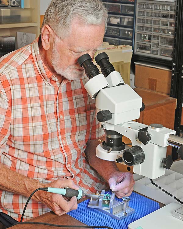
As I soldered the driver ICs, I got better with each chip but still had a long way to go to match the finesse in the video. Figure 7 shows me slaving over a hot iron, happy as a clam.
FIGURE 7. I successfully soldered the SMD components with a chisel tip iron, 0.015” solder, and flux pen.
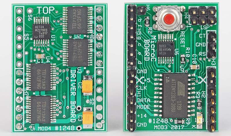
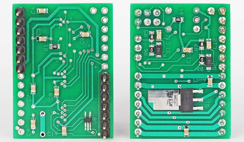
Additional closeup photographs of the fronts and backs of the final populated PCBs are shown in Figures 8 and 9.
FIGURE 8. Front view: The six-pin ISP programming connector is in the upper right of the right MicroC board.
FIGURE 9. Rear view: The five-pin single inverter chip (U8) is located on the back of the left driver board, in the lower right.
Programming the ATtiny2313
I chose to program the ATtiny2313 in assembly using Atmel Studio because I had used the same chip in another recent project. The only tricky part was the “missed pulse” section that locked in the dial count when the rotary dial finished turning. The rest was easy.
Actually, if you just want to use SPI to talk to the displays, a smaller chip could probably be employed, including PICs. The assembly program is available with the article downloads.
To program the µC, two different Atmel In-System Programmers (ISP) are available. The AVRISP mkII is obsolete but still available on eBay for about $50. The current AVR programmer/debugger from the manufacturer is the ATATMEL-ICE for $91. In both cases, when the chip is being programmed, it has to be powered-up by a separate 5V supply.
That concludes my description of the design, construction, programming, and operation of the EMDs. However, I’d like to say a few more words about my “ambitious” telephone project, in case anyone is interested.
So, What’s this Telephone Project all About?
In days gone by, telephone operators manually routed the calls by using switchboards with plugs, jacks, lever switches, and lots of wires. It was labor-intensive, but nice to hear the operator say “Number Please?”
In 1891, a man named Strowger envisioned an electromechanical system to replace the operators. The end result was the rotary dial which selected the number to call, and electromechanical step-by-step (SXS) switches to automatically route the calls.
Soon, the Central Offices were filled with thousands and thousands of clicking step-by-step switches, and operators were only needed for long distance calls. Over the years, improvements were made to the switches, but electronic switching gradually took over. By the 1990s, the SXS switches were completely phased out.
This brings us to my vintage step-by-step switching system. I embarked on the project — called a Private Branch Exchange (PBX) — because when I was a kid I went on a field trip to the telephone company and the rows and rows of clicking SXS switches left a lasting impression on me. With the advent of eBay, it’s much easier to find old telephone equipment.
I bought the five SXS switches from a guy on the east coast. I built a sturdy frame for them and added a ton of electronics, displays, relays, switches, lights, power supplies, and an Arduino Mega to make them do some fun things.
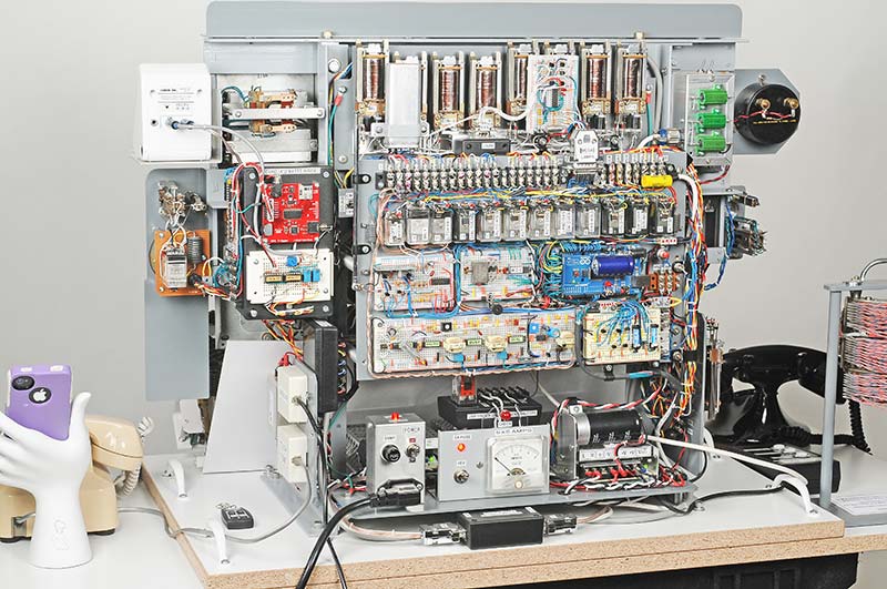
A photo of the backside of the PBX with its numerous subassemblies is shown in Figure 10.
FIGURE 10. The back of the telephone demonstrator contains numerous subassemblies, relays, and a blue Arduino Mega 2560 system controller.
In operation, my PBX can pulse-dial and ring the touch-tone phone (#54321).
It can connect to an outside line by dialing 9, then dial up any number in the world, including cell phones. Plus, I used the Arduino Mega to add a six-number auto-dial memory function much like modern phones.
Finally, it has a secret “Spirit of the Telephone” hidden inside the circuitry that randomly replays Alexander Graham Bell’s first call in 1876, and a comedic routine by our favorite TV operator, Lily Tomlin.
I’m not alone in my fascination with old telephones. There are two major groups — Antique Telephone Collectors Association (ATCA) and Telephone Collectors International (TCI) — whose members have constructed much more elaborate (by a factor of 100) step-by-step switching systems in their garages and basements. These folks are really serious about vintage telephones and telephone equipment.
Afterthoughts
Hopefully, other innovative experimenters will find applications for these funky displays and devise alternate schemes to drive groups of them, which may cut down on the number of components.
In the meantime, just remember, steampunk rules! NV