The weather in my part of Florida on the Space Coast is usually very nice in the winter. That being said, it is not unusual for the temperature to get into the mid 30’s on an occasional winter night. It was one of those rare instances that prompted me to create this project.
My solar collector is a good heat absorber, and unfortunately, equally good at radiating that same heat back out to the sky. This means the collector can drop below ambient temperature during cool clear nights. On one such night, the water in the collector froze and the pipes burst. My old solar controller failed to perform its job, which is to pump hot water from the tank in the utility room into the collector on the roof for freeze protection — the circuit had apparently become unreliable. Thus my plan to build another controller!
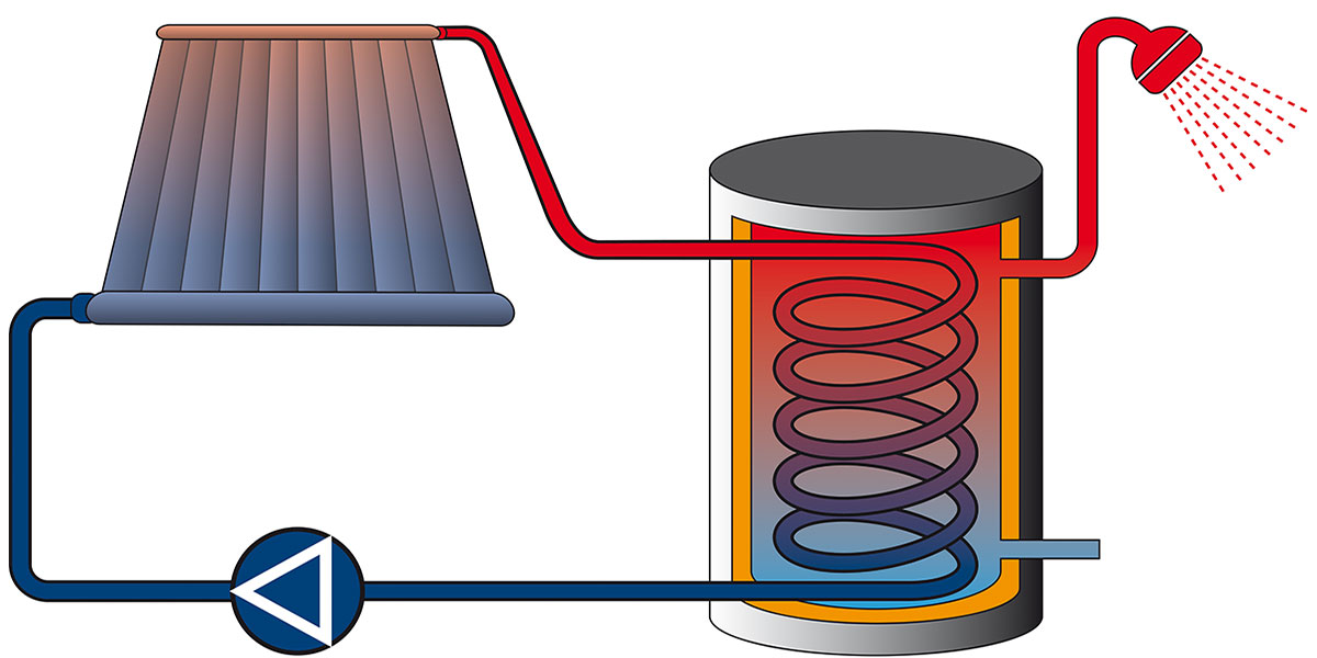
Collector Basics
The collector is made up of copper tubing and copper flashing sheets, assembled in an aluminum box with a glass cover. Its dimensions are 10 feet by four feet and about three inches thick. To start this project, I installed LM35DT sensors at the inlet and outlet of the collector. I also opened an access hole at the exact center of the collector and installed another sensor there.
A neat way to mount the LM35DT (which is available in a TO-220 package) is to solder a 6-32 flat head brass screw directly onto copper pipe to be sensed. I used brass nuts and thermal compound to complete that installation.
The pump for the system draws about 100 watts while running, which is a lot better than the 1,500 watts used for the heating element. I found that with my system, this heating element operates after about two days of no sun. Its thermostat is set at 120ºF on the element, however, it only takes about two hours of full sun to get up to this temperature, and even in mid winter, water temperature is usually far above that.
The typical temperature is somewhere above 160ºF in winter and higher for summer. With the original installation, the pressure/temp relief valve (195ºF) at the collector top would occasionally pop off, therefore during collector repairs, I installed a high temperature version (210ºF). This lets you know what kind of temperatures can be expected in the summer around here (if you’re a copper heat absorber).
The hot water tank is the “standard solar water heater” which has four pipes of different lengths fed into the top of the tank housing. The house feed line takes hot water from the top of the tank, and the water feed into the tank goes approximately half way down into the tank. The water to the collector is pumped from about six inches above the bottom and the collector output is inserted about 18 inches from the bottom. The hot water migrates to the top of the tank through the convection process.
These tanks are available from most solar utility companies here in Florida. They can also be obtained on-line or through special order from a plumbing supply company. My tank is about five feet high, with a 24 inch diameter and holds 80 gallons. A thermal sensor is mounted on the exterior surface at the bottom of the tank. The output of this sensor is included in my code as the variable “Tbot.”
Design Approach
The old controller is one of those old-fashioned transistorized versions that has a slide switch that was constantly getting dust contamination. It uses a transistor flip flop clock and several other transistors for relay control. It also has an advanced 741 op-amp used as a comparator and some 4066 DIP solid-state switches. I decided to use a programmable device rather than go through the component selection routine required to match the design of the original controller. I wanted to eliminate the mechanical relay, open slide switch, and nonlinear thermistors, as well. I needed something in a small package and finally settled on the 14 pin DIP PIC16F684. This chip was selected because it has eight A/D channels with 10 bit resolution, which will work well with the LM35DT linear temperature sensors.
Circuit Design
My original idea was to make a controller for the pump only, but I later added the digital readout for the temperatures. This is the reason my design uses two of the PIC16F684 packages. The schematic and printed circuit board (PCB) were designed using software from ExpressPCB (see Resources). I found their design software very easy to use, but note that you should do a line by line check of your design, as there are no error detecting features to check your layout for mistakes.
Your PCB data created in their software is uploaded to them and the order is placed for the boards (images of the PCBs and parts layout, as well as the code listing, are available in the downloads at the end of the article).
Board assembly is fairly easy due to the DIP devices and through-hole components. No SMDs are used. The components in the regulator circuit (Q5, C1, C2, and C3) are placed on the bottom side of the board to allow the board to be mounted a 1/4 inch from the surface of the box’s front cover. TB1 is also mounted on the bottom for better access to its terminals. See Figures 1 and 2 for photos.
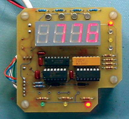
FIGURE 1. Assembled and working.
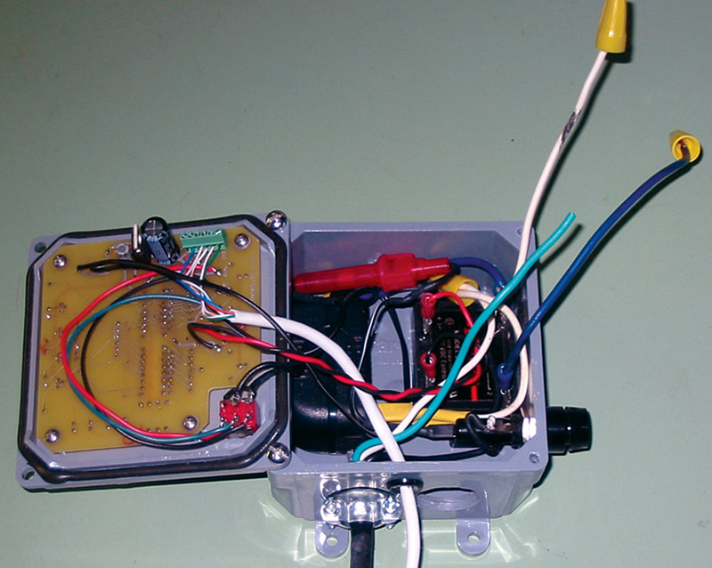
FIGURE 2. Ready for installation.
Schematic Details
Each LM35DT sensor has the 5V supply decoupled with 0.1 µF capacitors and a 1.0 µF capacitor in series with a 10 ohm resistor to account for capacitive effects of long wire runs. The compensation is probably not needed in my case, as the wire runs are only about 30 feet long.
Each sensor output is fed to an A/D channel on the first PIC16F684 (U1). There, the signals are converted to digital data, using 2.5V as a reference. The reference voltage is derived from the R14 and R15 voltage divider on the 5V supply. The digital data are compared in software to make the decision of “pump on” or “pump off.”
The pump is controlled from port RC2 by sending a signal to the solid-state relay (U10) and to a pump running an LED (DS2) to indicate status. Another LED (DS3) is controlled by port RC3 to indicate if the pump is running because of freeze protection.
Other tasks performed include sending each temperature reading to the second PIC16F684 (U2) for display, and clocking decoder (U3) for the purpose of turning on LEDs that indicate which temperature is being displayed. The data received by U2 controls the quad seven segment display. Half of the U3 decoder is also used in this process, along with associated display driver transistors.
The power supply consists of a 9V wall block regulated to 5V using a LM7805 regulator. A fairly heavy filter capacitor (C2) is 1,000 µF which guards against major voltage drops, allowing the system to work properly during the switching of S1 from pump “automatic” to “run” mode. See Figure 3 for the schematic.
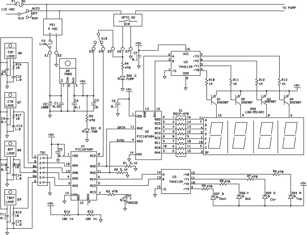
FIGURE 3.
Software and Testing
I used Microchip’s MPLAB IDE along with the PICC compiler from Hi-Tech for writing the software. One advantage of the MPLAB utility is its ability to perform simulations on the code. I made many iterations from the editor to the compiler to the simulator before creating something that worked as I wanted. For programming the PIC, I used the Microchip PICStart Plus unit. Be aware that the PICStart requires an RS-232 port, and some laptops (such as mine) have only one on its associated docking block.
There are two program listings used here, one for each of the PIC16F684s. The real controlling happens in “Thermal.c,” code for (U1). That’s where the pump on/off decisions are made. This program will turn the pump on when the collector’s top outlet has a temperature greater than five degrees above the bottom of the hot water tank, and runs the pump until the top temperature is only two degrees above the tank bottom.
For freeze protection, it will turn the pump on when the center of the collector drops to 37 degrees, and runs it until the center temperature is greater than 42 degrees. It indeed works, because I stood there and watched it on one of our cool February nights. I was surprised that it only takes one or two minutes of pump on time to satisfy the unit for protection.
The original system only sensed the top and bottom of the collector, but my reasoning told me the center of the collector should be the most temperature variable part of the collector. The first installation of the new system has shown this to be true, so I modified the software to sense the center temperature for freeze protection.
The “Thermal.c” code also converts each of the sensor readings from Celsius to Fahrenheit, then produces a data stream of each reading that is sent to the “Display.c” code for (U2). “Display.c” takes the temperature data and displays it on the quad seven segment LED display. Four LEDS of different colors indicate which temperature is being displayed. The three other LEDS indicate an “active pump,” “power”, and “pump running for freeze protection.” Again, all program listings are available in the downloads.
Hardware Packaging
In order to have a controller that could be easily installed, I opted for a PVC junction box from a local home improvement store. See Figure 2 for the large component placement. The 9V power block was modified slightly by soldering wires to the AC prongs and using shrink tubing. The block is then bonded into the box using RTV rubber cement (GOOP). The solid-state relay is fastened to the box bottom with 6-32 hardware. The fuse holder F1 is mounted in the box and F2 is on pig tails and stuffed into the box.
Use care when installing the front panel with the PCB attached, as there is not much clearance left. The box is only a 4” x 4” x 2” and, in hindsight, a 5” x 5” board would have been easier. The fuse holders and power block (PS1) are from RadioShack. All the other components are from Digi-Key. The solid-state relay (Q10) is from All Electronics.
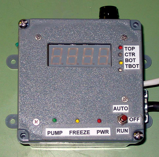
FIGURE 4. The finished project.
Future Improvements
For the future, I would like to add a data logger that will put the temperature readings onto a Flash drive. Then I could load the data into Excel and make a chart of the results. Currently, I am reading these data manually with four hour readings and a clip board. I’m looking to use the PIC16F877 for this upgrade, but not sure something that powerful is required.
Maybe I can think of something else for it to do, like monitor solar intensity for calculations on a photovoltaic system to run the pump. That way, I will have totally free hot water. NV
Resources
All Electronics — allelectronics.com
RadioShack — radioshack.com
Home Depot — homedepot.com
Microchip — microchip.com
Hi-Tech Software — htsoft.com
ExpressPCB — expresspcb.com
Digi-Key — digikey.com
PARTS LIST.
| ITEM |
DESCRIPTION |
PART NO./SUPPLIER |
| C1 |
.22 µF 250V |
ECQ-E2224KB/Panasonic |
| C2 |
1,000 µF 25V |
UVR1E102MPD/Nichicon |
| C3 |
10.0 µF 50V |
UVR1C100MDD/Nichicon |
| C4-C11 |
0.1 µF 50V |
ECQ-V1H104JL/Panasonic |
| C12-15 |
1.0 µF 63V |
2222 021 38108/BC Components |
| DS1, DS5 |
Red LED |
SSL-LX3044LID/Lumex |
| DS2 |
Green LED |
SSL-LX3044GD/Lumex |
| DS3, DS6 |
Yellow LED |
SSL-LX3044TD/Lumex |
| DS5 |
Orange LED |
SSL-LX3044SOC/Lumex |
| DS7 |
Blue LED |
SSL-LX3044USBD/Lumex |
| DS8 |
Quad seven seg |
LDQ-M514RI/Lumex |
| F1,2 |
Fuse holders |
1/4 A and 2 A/RadioShack |
| PS1 |
115 VAC to 9 VDC |
RadioShack |
| Q1-4 |
PNP Transistor |
2N2907/STMicroelectronics |
| Q5 |
5V Regulator |
LM7805CT/Fairchild |
| Q6-9 |
Temp sensor |
LM35DT/NOPB/National Semi |
| Q10 |
Opto Relay |
SRLY-18 /All Electronics |
| R1-2 |
5.11K 1/4 W |
MFR-25FBF-5K11/Yageo |
| R3-9 |
475 ohm 1/4 W |
MFR-25FBF-475R/Yageo |
| R10-13 |
1.0K 1/4 W |
MFR-25FBF-1K00/Yageo |
| R14-15 |
10.0K 1/4 W |
MFR-25FBF-10K0/Yageo |
| R16-19 |
10 ohm 1/4 W |
MFR-25FBF-10R0/Yageo |
| S1 |
DPDT ctr off |
100DP3T1B1M1QEH/E-Switch |
| TB1 |
Six Pos term |
1725698/Phoenix Contact |
| U1,2 |
PIC16F684 |
Microchip |
| U3 |
Dual 2 to 4 DEC |
SN74HC139N/Texas Inst |
| Z1 |
RDIP-470 |
4116R-1-471LF/Bourns, Inc. |
Downloads
200708-Aidt-SolarThermal-Water-Heater.zip
Water Heater Controller - PCB detail and code listings