So, my wife volunteered me for “Science Day” at my son’s elementary school — an annual half day program where moms and dads taught mini-courses on everything from rocketry to zoology to chemistry. But what could I teach the kids? No sooner did the thought cross my mind, did I get the answer: build a video game!
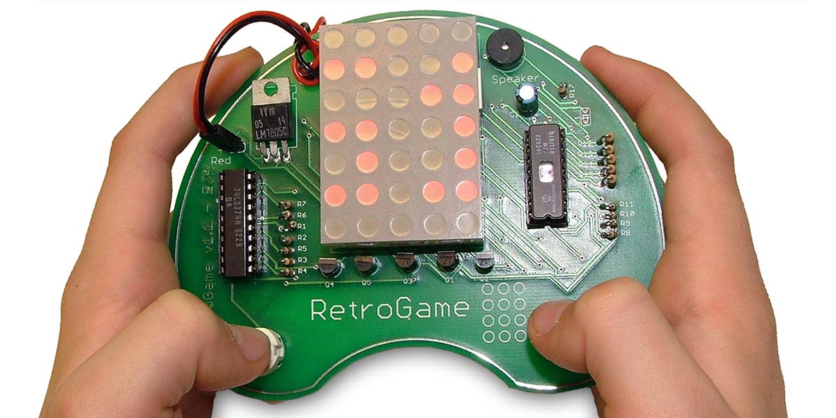
Thus, the “RetroGame” was born. The RetroGame is a simple hand-held video game that was designed to be assembled by third to fifth graders during a 45 minute Science Day period. The game physically consists of a PCB (printed circuit board) with a 5x7 LED matrix display, two pushbuttons, and surrounding control and power electronics. The games were fully soldered by the time the kids got them, but the main parts including the processor and display were socketed, so the kids would have to “assemble” the games themselves. I created two games for the RetroGame, each as a separate firmware load for the processor PIC:
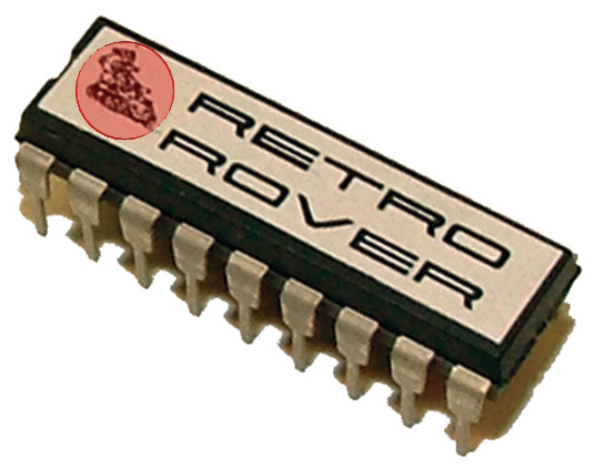
RetroRover 2006
In this game, your “moon rover” (a flashing LED) has to make its way through rough terrain which constantly approaches from above. The buttons allow you to move from side to side.
FIGURE 1.
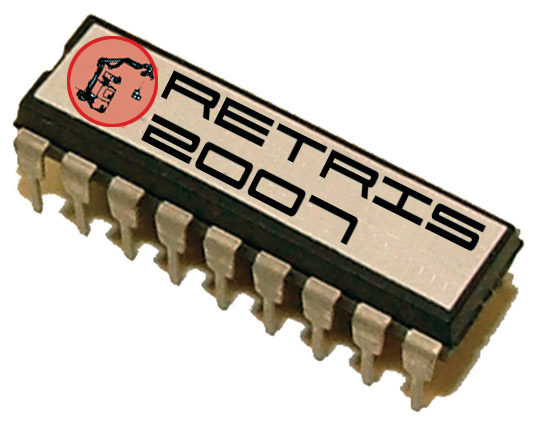
Retris 2007
This is a mini Tetris where small pieces can be moved from side to side, but not rotated. This proved to be the most popular game.
FIGURE 2.
I would have created a few more games, but ran out of time. The software architecture lends itself to (relatively) easy game creation, fortunately.
Building the RetroGame
My first task was to do the basic design of the game, and then try to procure the cheapest parts I could, which would then drive the final design of the circuit and layout of the PCB — though I already knew that I wanted the PCB to look like a retro video-game controller. After finding the basic parts, I went on a search for a cheap processor.
I decided on a PIC 16C620. It was small with 18 pins, and had a useful amount of memory. Most importantly, I could get a bunch of them cheap! Since the game is simple, very few I/O pins were necessary. In fact, one remained unused ... which never happens in any of my projects.
I wasn’t sure how much memory I needed at first, so I started with the 620, but quickly realized that movng up to a 622A would be necessary. They are pin-compatible, so it was an easy move.
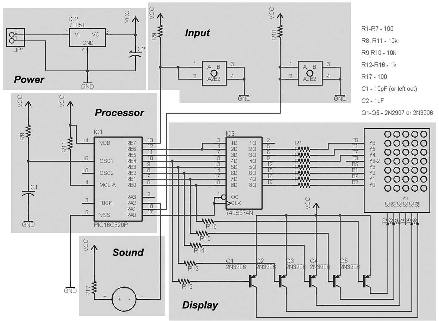
The RetroGame circuit itself is very simple, and consists of the following basic sections:
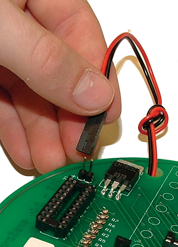
Power: As my concerns were more with cost than efficiency, the power section of the circuit uses a 7805 five volt regulator that converts the nine volts from the battery. The regulator is old technology that you can get very cheaply, but it uselessly dissipates a bunch of heat when in use. You should notice fairly quickly that there is NO power switch for the RetroGame. To turn it on, you plug in the battery connector. Eliminating the switch saved some money and the kids loved the hands-on feel of plugging in the power.
FIGURE 3.
Input: Two momentary push buttons pull two input pins of the PIC controller to ground when pressed. Otherwise, pull-up resistors (R9, R10) pull them to +5V. These pushbuttons are the only user input for the game. I used cheap switches which “bounce” quite a bit. The software deals with this issue. I briefly considered adding a third pushbutton (because I already knew I wanted to create Retris and wanted rotation) but abandoned the idea in favor of simplicity.
Processor: The processor section consists only of the PIC 16C622A (the generic 16C620 is shown in the schematic). Note that the internal oscillator is being used for the clock. Since this is just a video game, the precision of a crystal-controlled clock is unnecessary. Note, too, that in the schematic that C1 can be left out. I left it out for the kids; you’ll see why later.
Sound: The sound part of the circuit consists primarily of a little piezo-electric speaker that is connected directly to one of the processor I/O lines. Sound is produced by bit-banging the speaker. (See the section on RetroGame Sound.)
Display: The most complicated part of the circuit is the LED display section. It consists of the 5x7 LED matrix along with a data latch and transistor column drivers. The LEDs on the matrix are rapidly flashed, as described in the section on RetroGame Display.
The circuit was originally created on a breadboard, which allowed experimentation mostly on the display section. It also allowed me to begin software development while I waited for the PCBs to be manufactured.
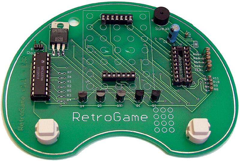
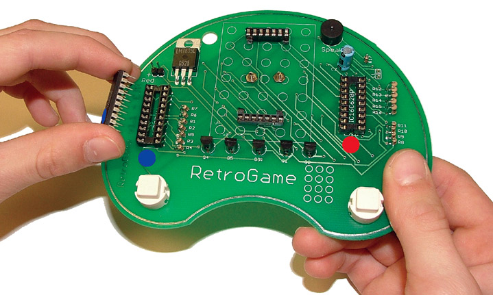
Arguably, the coolest part of the RetroGame is that you play it while holding on to the PCB itself which is shaped like an old video game controller. The silver strip running around the circumference of the PCB is just for looks.
FIGURE 4.
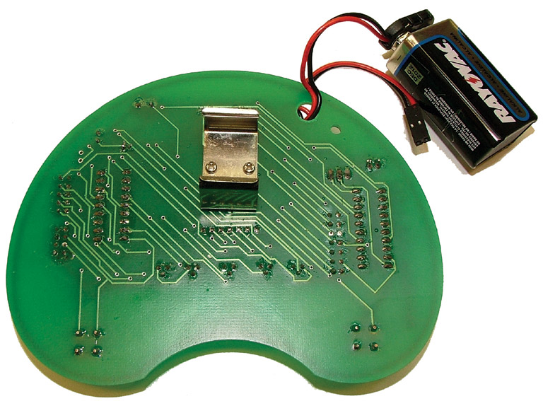
Creation of the PCB was relatively simple. I used the Eagle editor for a simple two-sided through-hole design with parts on one side only — almost. The battery holder is attached to the back of the RetroGame with two screws and nuts.
Although it’s obvious that no components could be soldered where the metal battery holder was placed, what wasn’t obvious to me at first is that the vias from top to bottom needed to be kept away from the holder area too. I could count on the PCB solder mask to prevent short circuits due to the battery clip contacting traces, but I couldn’t count on it to protect the vias. So, I set up the battery holder area in the design to exclude vias ... simple.
FIGURE 5.
Populating the PCB was easy with the through-hole design. The only interesting detail is that the major components were to be socketed, allowing the kids to be involved in the assembly. The display driver and the PIC would have normal sockets. The LED matrix, however, needed something special — two single row, seven-pin sockets. If you haven’t looked lately, those things are expensive. Instead, I simply cut a 14-pin socket in half.
The socket for the display also served to keep the display away from the screws that attached the battery holder to the back of the PCB.
You may notice that there is no heatsink on the 7805. There probably should be, but the circuit doesn’t draw too much power, so in practice it doesn’t get too hot. To mitigate the potential for a kid to burn a finger, I mounted the 7805 flat against the PCB.
FIGURE 6.
Science Day Cometh!
The RetroGame was done in plenty of time for Science Day, although I still had quite a bit of work to do to get ready for the kids. One important issue that I wanted to prevent was potential incorrect orientation of the ICs. The display wasn’t a problem in that it can be mounted in either orientation.
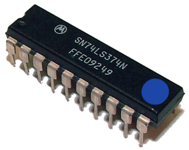
To solve the PIC orientation problem, I simply used little colored stickers. The PIC had a red dot on it (which doubled as the game label) and the 74LS374 had a blue dot on it. The dots were strategically placed on one end of each chip, and a matching dot was placed on the PCB itself. The kids just had to line them up!
FIGURE 7.
FIGURE 8.
FIGURE 9.
Science Day went great! We had 100% success rate with 65 third through fifth graders assembling and playing their own video game. There were a few problems (like bent pins) and a couple resultant messed up sockets, but spare parts solved the problems.
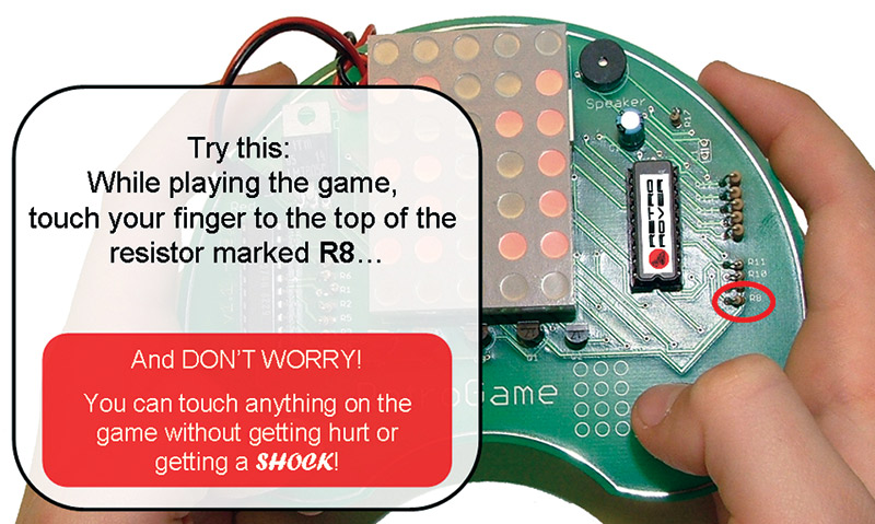
Remember that I didn’t recommend installing C1 in the final RetroGame? C1 is the capacitor that helps set the frequency for the internal PIC oscillator. By not installing it, I found that you could easily affect the speed of the clock with your finger. In fact, you could slow the game down dramatically to the point where you could see the flashing of the display, and the game itself would operate so slowly you could get yourself out of problems. I was somewhat surprised by how quickly the kids were able to take advantage of this little trick! One student even figured out how to lay his finger on the underside of the board when he needed it.
FIGURE 10.
RetroGame Display
The display for the RetroGame is a row cathode, column anode LED matrix. At first glance, you may ask yourself, how do you individually drive 35 different LEDs with only 12 signal lines? Fine question.
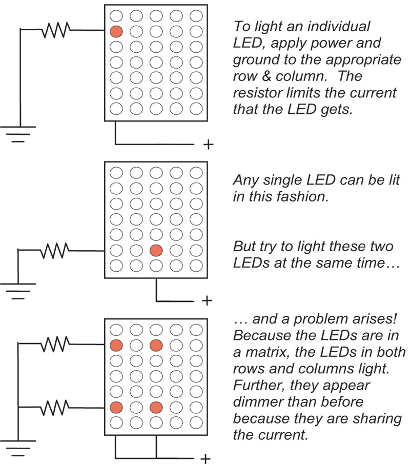
As the name implies, the display is a “matrix” of LEDs. The cathodes (-) of each LED in a given row are connected together, while the anodes (+) in a given column are connected together. To turn on an LED, you apply power and ground to a row and column, respectively (through a resistor).
FIGURE 11.
So, to use an LED matrix a standard “trick” is employed. The trick is to only light one column of LEDs at any one time, and to rapidly cycle through the columns giving the illusion that two LEDs in different columns are on at the same time. The rows are then synchronized with the particular column that is being “lit” at any one time. Do this over and over — and fast enough — and any set of individual LEDs can appear to be on at the same time.
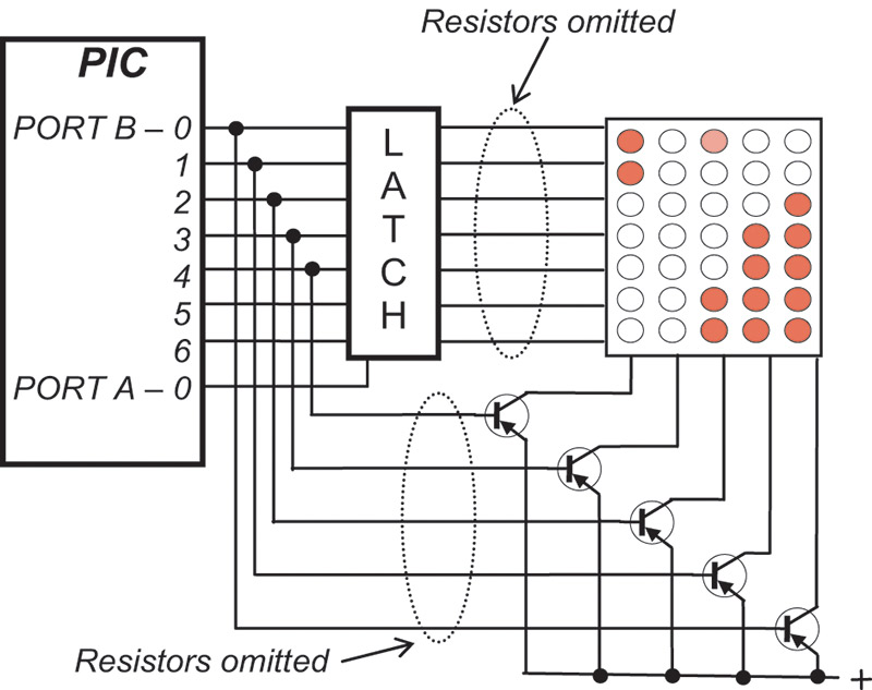
The diagram in Figure 12 is a simplified (though not by much) schematic of the LED matrix in the RetroGame.
FIGURE 12.
The resistors have been removed to make it look less cluttered for this discussion. In the RetroGame, the columns are driven by transistors, one of which is on at any point in time. The rows are driven by data that is latched into a data latch.
The algorithm for driving the display is:
Place the first column data on port B lines 0 through 6 (seven bits). This data corresponds to the particular LEDs which should be lit in the first column.
Drive port A bit 0 high, which is connected to the data load line of the latch. This both latches in the column data, and holds the latch output lines high while the line is held high — effectively “blanking” the matrix.
Set the column number (the first column in this case) data into port B lines 0 through 4 (five bits). This will turn on the associated column transistor.
Finally, pull port A bit 0 low, which allows the previously latched column data out on the latch output lines, lighting the target LEDs in the first column.
Leave the display in this state for a bit and then start over at step 1 with column 2 data driving the column 2 transistor, followed by column 3 — and so on. After lighting column 5 LEDs, the process starts over at column 1. Do this fast enough and a human observer won’t see any flashing. Source code files used for the display are display.asm,display.h, and display.mac (available in the downloads).
RetroGame Sound
To generate sounds and music, the RetroGame uses a technique called bit banging. This quaint little term describes the brute-force method of manually raising and lowering a signal line (bit) to generate a particular shape of signal over time on the line. In the case of the RetroGame, the signal is a certain frequency of music or sound.
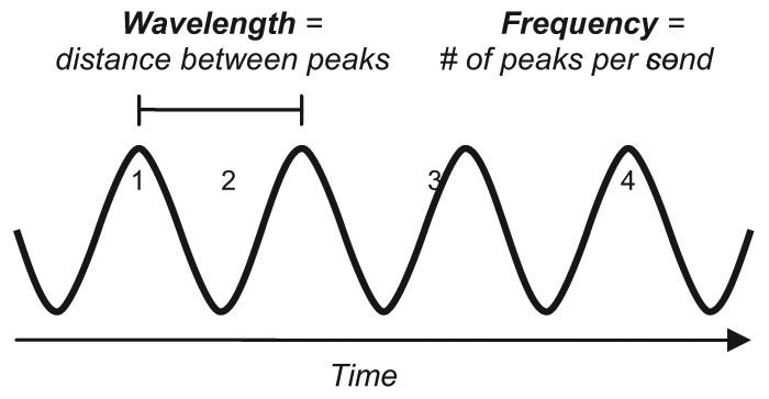
Normally when you see a representation of a sound, or the “waveform” for a sound, you see something like what’s shown in Figure 13.
FIGURE 13.
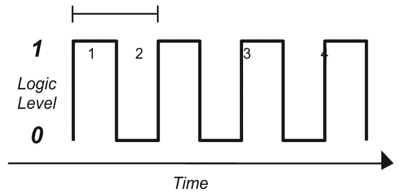
The RetroGame waveform has the same features but looks quite different (see Figure 14.)
FIGURE 14.
The PIC generates this waveform by alternately raising and lowering a digital signal at a particular frequency. In other words, the PIC raises the signal line, waits for an amount of time equal to half the wavelength, lowers the signal, waits for another half wavelength, then raises the signal again. The following code snippet is from the RetroGame files (modified to make it easier to read):
By adjusting the time the PIC waits between the raising or lowering of the sound line, different frequencies can be produced.
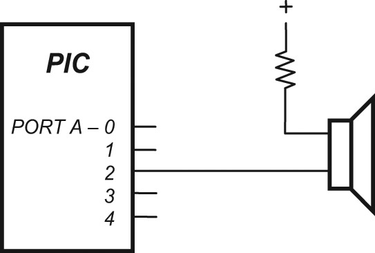
In the RetroGame circuit, the signal line that generates the sound is connected directly to the speaker, with the other end of the speaker connected through a resistor to +5V (Figure 15).
FIGURE 15.
There is a problem with bit-banging like this. While the PIC is generating a sound or music, it can do very little else. In essence, it has to give its full attention to generating the sound. Granted, with some very judicious programming, the time spent waiting between the raising and lowering of the sound line can be used to do other things. This isn’t easy, particularly given that music is far more interesting with different frequencies — some of them quite high. Plus, high notes have much less wait time between signal line transitions.
The RetroGame can play two things: music and beeps. To play music, it stops doing everything else, including updating the display. As such, whenever music plays, the display blanks. To make beeps, it is actually smart enough to use the extra time to update and move the display. Source code files used for music and sound are music.asm, music.h, music.mac, musicdata.asm, musicdata.h, and musictable.mac (also available in the downloads).
RetroGame Software
The RetroGame circuit is relatively simple, but the software is somewhat more complicated — not too complicated though, and it is pretty small, fitting into a PIC 16C622A.
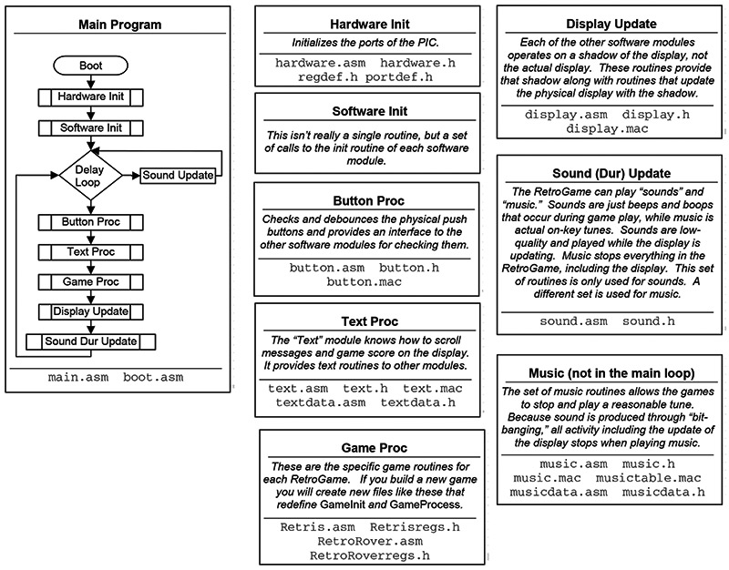
All activity in the RetroGame appears to be occurring concurrently. That is, the game is moving on the LED display while sound is being made and the buttons are moving Retris pieces. It should be no surprise, however, that all activity is actually occurring serially but at high speed so you can’t tell the difference. In more sophisticated programs on more sophisticated processors, a real-time operating system provides the mechanisms by which many tasks can appear to be operating concurrently. In the RetroGame, however, no real-time OS is used. Instead, a simple brute-force activity loop is employed which:
Checks the buttons.
Changes and updates the display (for text or game play).
Plays beeps and “non music” sounds.
During each round through the loop, a small bit of each software module runs before it returns to the main loop. Each module gets a turn during the loop,accomplishing a small piece of its task and keeping track of its position for the next round with a state machine.
The main loop includes a delay which sets the speed of the game. The only thing that occurs during the delay is the production of sounds.
FIGURE 16.
RetroGame Music
The music module in the RetroGame is rather interesting and could easily be adapted for other PIC projects. Implemented in the following source files, the music routines provide an easy mechanism for integrating music into any PIC application:
music.asm (.h): Implements the music playing routines, though none of these routines are called directly. Instead, the macros in music.mac are the interface to music by other modules.
music.mac: Implements the macro “MusicScorePlay” which will play the given musical score. Note that music.mac automatically includes musictable.mac.
musictable.mac: A very large macro that interprets a musical score, setting the appropriate values for the desired note. Note that this entire file is generated by a C program that takes into account the clock speed of the PIC.
musicdata.asm: Musical scores for “standard” game music are in this source file.
As an example of how to use the RetroGame music system, here is a snippet from the source file musicdata.asm:
This snippet creates a data table with a musical score that can later be played with:
MusicScorePlay Dirge
The fields of the macro MusicNoteTableEntry are:
Field Description
1* The musical note: C, D, E, F, G, A, B, or R for a rest.
2* Modifier for sharp or flat: # or b.
3 Octave – from 0 (zero - low) to 8 (high).
4 Duration from 0 to 3.
5 Set to 0 (zero) for smooth and 1 for staccato.
*Fields 1 and 2 must be enclosed in quotes.
The MusicNoteTableEntry macro creates two lines of code per macro. The Dirge score above, therefore, occupies 22 instruction slots, plus two for the MusicNoteTableDone macro. In other words, each musical score with N notes occupies 2(N+1) instructions slots.
In Retrospect
To be honest, I’m not sure if I or the kids had more fun with this project. I hope this article will encourage you to step up your game using electronics. NV
The Retro Game is Fun to Build and Fun to Play.
Demonstration of the RetroGame running the Retris 2007 game. Note that the display actually has RED LEDs, although they look white on this video — it's some artifact of the video recorder I used. Also, listen closely for the sounds the game makes, they are faint because the video microphone was not close to the little speaker. The opening and closing text has examples of the sound too.
RESOURCES
www.rothfus.com/RetroGame
All of the source files for this project can be found here, including:
• PCB “gerber” files
• Software source code for both games
• Mini-manuals for both games
• Original PowerPoint presentation for Science Day
• Videos of the RetroGame in action
Sunstone Circuits —www.sunstone.com
These guys are great! Besides offering an excellent PCB fabrication service, they have a community outreach program that helped pay for the PCBs for the kids. Thanks guys!
Silicon Hills Design —www.siliconhills.com
A local electronics assembly and service house in Austin, Silicon Hills graciously assembled the boards for the kids.
PARTS LIST
ITEM
QTY
DESCRIPTION/PART NUMBER
R1-R7 and R17
8
100Ω resistor 1/4 or 1/8 watt
R8-R10
3
10K resistor 1/4 or 1/8 watt
R12-R16
5
1K resistor 1/4 or 1/8 watt
C1
1
10 pF (optional)
C2
1
1 µF
Q1-Q5
5
2N2907 or 2N3906
IC1
1
PIC 16C622A
IC2
1
74LS374N
5x7 LED matrix
1
(see below)
Speaker
1
Small piezo-electric speaker
Pushbutton
2
Battery clip
1
Nine volt clip with two pin connector
JP1
1
Two pin battery connector
Battery holder
1
Small screw/nut
2
For mounting the battery holder
14 pin IC socket
1
Cut in half to form socket for LED display
18 pin IC socket
1
Used for 74LS374N mounting (optional)
20 pin IC socket
1
Used for PIC (optional)
7805
1
Regulator
Most of the parts for the RetroGame are easy to find. This table provides sources and part #’s for the hard-to-find parts.The LED matrix is sourced from many suppliers; check to see who has stock (and lowest price!)
ITEM
PART NUMBER
SOURCE
Speaker
AUD1080
BG Micro
Battery clip
BAT1064
BG Micro
Pushbutton
SWT1008
BG Micro
401-1963-ND
Digikey — white, other colors available
5x7 LED matrix
604-TA20-11SRWA
Mouser
LED1115
BG Micro
160-1560-5-ND
Digi-Key
Battery holder
12BH071-GR
Mouser
PIC
16C622A
Mouser
Links
The RetroGame Kit is available in the Nuts & Volts webstore.
The RetroGame PCB is available in the Nuts & Volts webstore.