When we purchased a condominium in Florida several years ago, one of the first things I did was install an Internet-accessible thermostat. We don’t stay in Florida during the summer months and I needed to be sure the air conditioning kept working. With the high humidity during the summer, a failure can mean the possible introduction of black mold into our home, which would be a major problem.
I purchased an Ecobee brand thermostat and was able to install it myself. I was fortunate in that the wiring in the condo used standard color code. The cable from the thermostat to the furnace/air conditioner didn’t have the needed common wire, but I was able to make use of an additional wire in the cable for this. (More later.)
This past year, we purchased a somewhat larger condo, and again I wanted to install an Internet-accessible thermostat. This time, I chose a Honeywell and I can recommend both brands. The wiring in the new home was a problem, unfortunately. Not all wires used standard colors and in addition, this heating/air conditioning unit also has a separate built-in humidity control. I ended up calling the company that installed the system and they came out and installed the new thermostat.
At this point, I realized there were several things I wanted to learn about thermostats. I determined to do some studying and then build one of my own design.
My focus here is on a fairly simple forced air heating/cooling system; take a look at Figure 1. There are several other systems (like heat pumps), and the whole subject of HVAC (Heating, Ventilation, and Air Conditioning) can be quite complicated. A review of the document http://ritetemp-thermostats.com/Professional%20reference%20guide%2021dec07.pdf should give you some insight into this complexity.
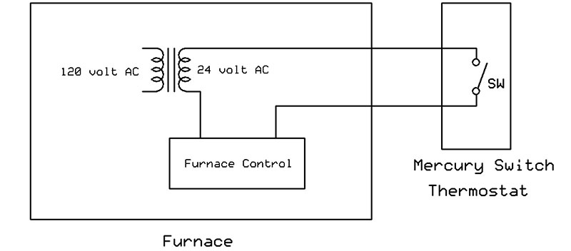
Figure 1. Simple thermostat connected to a furnace.
Figure 2 shows a representation of a simple mercury switch type of thermostat. A mercury switch is just a glass tube, sealed at both ends, with a drop of liquid mercury inside and two contacts at one end. The mercury acts as a switch when it touches the two contacts at one end.
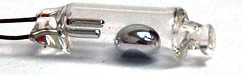
Figure 2. A mercury switch.
The mercury switch is connected to a bi-metallic coil which moves and closes the switch when it gets colder. This switch is connected in series with a 24 volt AC transformer ‒ a standard of the HVAC industry.
Once the 24 volt AC power is connected to the furnace control, it can signal several things; for example, open a solenoid on a natural gas line and provide electric ignition, then turn on a blower fan.
Note the simplicity of the design. The thermostat is just a basic switch that needs no power; all the control is built into the furnace.
Mercury switch thermostats have been replaced with other types because mercury is a poisonous heavy metal and devices containing mercury switches must be treated as hazardous waste for disposal.
A more modern thermostat model is shown in Figure 3. The thermostat I have in my home in Michigan is very similar to this but doesn’t have the “other control” or the five volt power using the common line.
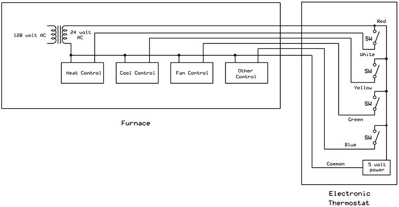
Figure 3. More modern thermostat connected to furnace/air conditioner.
Standard color codes are red for power, white for heat, yellow for cool, and green for fan. Be aware than non-standard colors are often found. My thermostat is a Honeywell Type T87F which comes in several different models. It still is electro-mechanical and uses a mercury switch, but one that has contacts on both ends of the tube. When it gets colder, the switch at one end of the tube closes to provide heat; when it gets hotter, it tips in the opposite direction and the switch at that end is closed to turn on air conditioning.
The Design
The block diagram of the all-electronic thermostat I designed is shown in Figure 4. It’s meant to replace the electro-mechanical Honeywell Type T87F in my Michigan home.
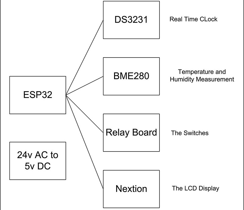
Figure 4. An all-electronic thermostat design.
The first problem I faced when considering the all-electronic thermostat is how to get the typical five volts needed to power the electronics. The older thermostat it’s replacing usually doesn’t need power.
This has been addressed by the HVAC industry by bringing the “common” line from the other side of the 24 volt AC transformer into the thermostat as shown back in Figure 3. There, it’s converted into the five volts DC needed. This allows consumers to install one of the new Internet-connected thermostats without having to consider how to get power to an old thermostat location.
The full schematic of the thermostat is shown in Figure 5 and consists of five small boards connected together for an easy build and a Nextion LCD display. A commercial manufacturer would no doubt lay out all the components on a single printed circuit board (PCB). Triacs would probably replace the quad relay board, which I used for a simple assembly.
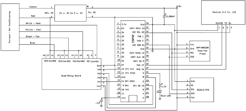
Figure 5. Full schematic of the all-electronic thermostat.
Figure 6 shows the 3D printed case for housing the parts, with the Nextion display mounted over a window underneath. The Sketchup and object files for the 3D printed case are available in the downloads.
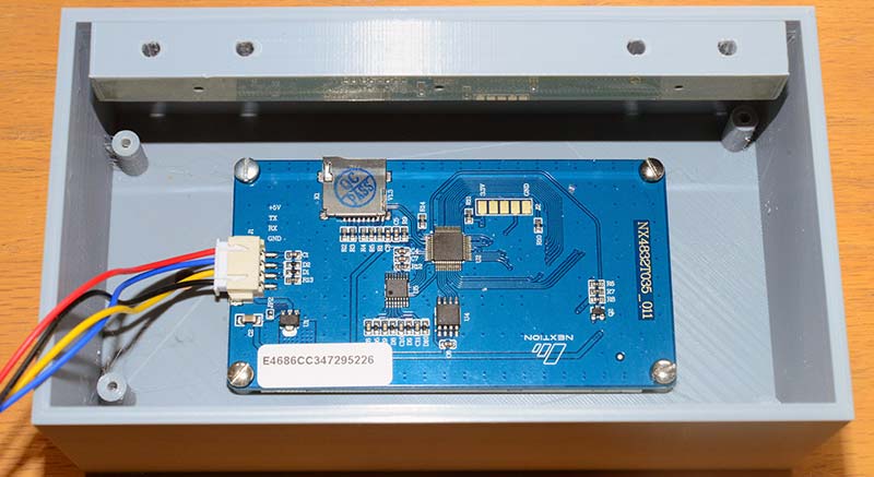
Figure 6. The Nextion display mounted in the case.
Note the mounting bar at the top of the figure; it’s actually attached to the bottom wall of the case. The mounting bar is screwed into the wall and then small 4-40 machine screws attach the bottom of the case to the bar.
The 3D printed case has two built-in standoffs to mount a point-to-point wiring breadboard on one side, and two additional standoffs on the other end to mount the quad relay board. These standoffs are tapped for 1/4 inch 4-40 machine screws. The mounted boards are shown in Figure 7.
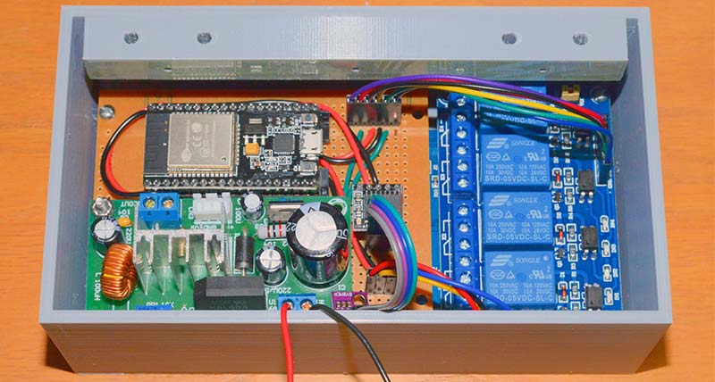
Figure 7. Additional components mounted on top of the Nextion display.
The breadboard also has header pins to connect the real time clock (RTC) module, the BME280 board to measure indoor temperature and humidity, and the Nextion display. While header pins work fine for this proof-of-concept model, a thermostat used continuously should have the modules wired directly.
A blue LED is connected to pin 4 of the ESP32. It’s brought out through a hole in the front of the case and used to denote an Internet connection. Mounted on a standoff on the breadboard is a 24 volt AC to five volt DC power supply. The red, white, yellow, and green wires to the furnace have not been attached to the relay board in this image.
The Nextion Display
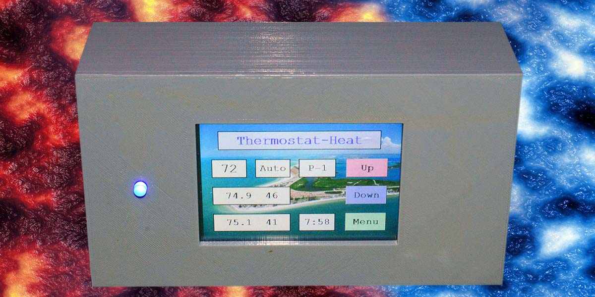
The Nextion display is the heart of this project and gave me an opportunity to learn about using and programming it. The learning curve for using the Nextion is fairly steep, however, the effort is certainly worth the benefits of using this new type of LCD display (Figure 8).
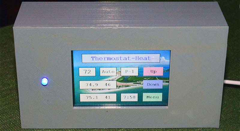
Figure 8. Front view of the thermostat.
These LCD displays come in several sizes ranging from 2.4 to seven inches diagonally. I chose the 3.5 inch for my project and selected the basic model. In retrospect, a larger model might have been a better choice for appearances.
In a traditional LCD display, a library is provided with a group of primitive commands like draw a line, draw a circle, draw text, etc. A good portion of the microcontroller’s program is spent in drawing to the LCD screen. Many lines of code are necessary to get professional looking results when drawing something complex like a temperature or pressure gauge. The lengthy drawing portion of the code can lead to delays in refreshing the screen ‒ especially when a new page is required.
The Nextion display takes a different approach. The LCD has its own processor and a design program ‒ called the Nextion Editor ‒ which creates a program you copy to the LCD. This makes placing text, buttons, gauges, and more on various pages of the display easy. To some degree, it reminds me of creating a Windows Form program using CSharp and the Microsoft Visual Studio GUI.
The Nextion Editor (shown in Figure 9) can then compile the display interface code. It’s then copied to the LCD by means of a micro SD card or via a serial connection.
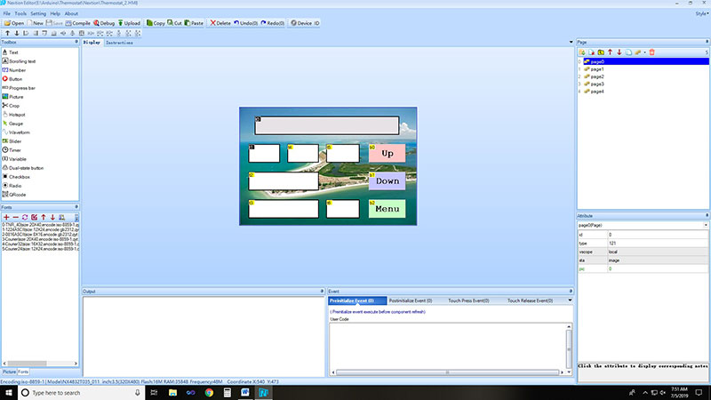
Figure 9. The Nextion editor.
I found using the SD card method quite easy. The SD card with the compiled code is inserted into a card socket on the LCD board and when powered, the board reads the card and installs the code. The card is then removed and when powered on, the LCD displays the pages you created in the Nextion Editor even if the display is not connected to a microcontroller.
When you click on a button or change text, the Nextion Display can send the appropriate data to the microcontroller. The display has only four wires for connections: +5 volts, ground, RX (receive), and TX (transmit). The RX, TX serial lines must be run at 9600 baud.
I stayed with simple text boxes and buttons and avoided some of the more complex components like gauges and sliders. I also sent and received commands directly between the ESP32 and Nextion display through a serial port and didn’t use their library.
It appears a full keyboard or keypad can be attached to a text box, but I was unable to make this work and could find nothing online about this feature.
A separate page was created in my project with a keypad to enter values into text boxes. This is the challenging part of using the Nextion display. Documentation is available but difficult to understand and examples of using many features are lacking. Several examples of using the Nextion display exist on YouTube, and although I found some of them fairly simplistic, they got me going.
To get started with the Nextion display, you’ll need the Nextion Editor which is a GUI program that creates the pages and components that will be displayed. You should begin by reviewing the Nextion Editor Guide, which can be found at https://nextion.itead.cc/editor_guide/. There’s a link to download the Nextion Editor in this guide. The Nextion Instruction Set can be viewed at https://nextion.itead.cc/resources/documents/instruction-set/.
I found Adreas Spiess’ YouTube clips helpful when starting. They’re available at https://www.youtube.com/watch?v=D-zgtylBKUc&list=PL3XBzmAj53RlXES3erPR4F0Zk08Hx1YdA&index=1. There are many other videos on YouTube you can explore as well.
Figure 10 shows page 0: the home screen of my thermostat project. Note that there are seven text box components and three buttons.
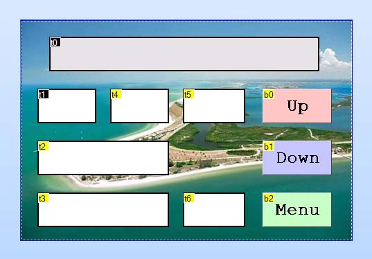
Figure 10. Page 0: The home screen of the thermostat.
A good way to familiarize yourself with the Nextion display is to open the Thermostat.HMI file (in the download area) with the Nextion Editor. This file contains the entire five page display program, and you can explore all of the components and their attributes.
The t0 text box at the top will contain the program title and heat mode, like Thermostat – Heat or Thermostat – Cool. The t1 text box contains the temperature setting; the t2 text box contains the current inside temperature and humidity; the t3 text box shows the outdoor temperature and humidity as obtained from the Internet; and the t4 text box gives the fan setting ‒ either On or Auto. The t5 text box contains a P-1 or P-2 symbol denoting that the thermostat in running in either Program 1 or Program 2 mode. The t6 text box contains the time and is updated once a minute. The three buttons raise or lower the set temperature or display page 1 (a menu).
Page 1 (which is the Settings menu shown in Figure 11) has five buttons and allows the user to select either Heat or Cool mode, change the Fan setting, or enter a Program.
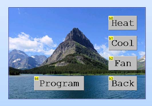
Figure 11. Page 1: Settings menu.
Page 2 (the Fan Selections page shown in Figure 12) simply sets the fan either always on or in auto mode where the furnace will assume control.
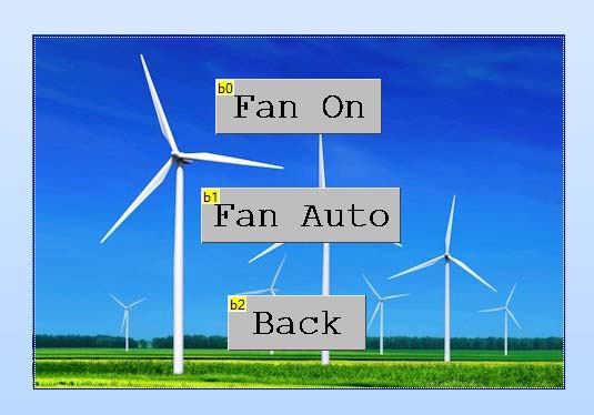
Figure 12. Page 2: Fan Selections.
In Page 3 (the Program menu is shown in Figure 13), the thermostat can be placed in program mode where the temperature can be changed twice a day. The upper two text boxes contain the time in a 24 hour and minute format like 7:30 or 22:45. The lower two text boxes contain the temperature to be set at the time given.
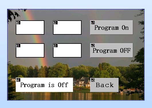
Figure 13. Page 3: The Program menu.
All temperatures are in Fahrenheit and integer numbers. The Nextion display jumps to Page 4 for inputting the times and temperatures when one of the text boxes is selected.
The time or temperature is entered from Page 4 shown in Figure 14. The Enter button keeps the entry and goes back to the Program page.
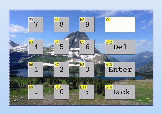
Figure 14. Page 4: The numeric keyboard.
The Back button discards the entry and returns to the Program page. When all four entries are completed, selecting Program On will send these values to the ESP32; Program Off will discontinue the Program mode.
Helpful Tips
Here are a few pointers if you’re just starting with the Nextion display.
After opening the Thermostat.HMI file in the Nextion Editor, you should see two panes at the left: a Toolbox, and a Font and Picture below. The latter has tabs at the bottom to switch between the two. Clicking on an object in the Toolbox will add it to the current page. You have to create each font you’ll use by clicking on the Tools Menu and selecting Font Generator.
Each font will have a number; this is used in the Attributes pane in conjunction with something like a text box or button to select the font. Pictures can be added in the Picture pane.
If you want to use a picture as the background of a page, be sure the pixel dimensions of your image match the screen size of the Nextion you have chosen. I have a 3.5 inch display with a 480x320 pixel screen.
On the right side is a Page pane and below an Attribute pane. You can add or move pages in the Page pane. If you click on a text box or button, you can view and edit its properties in the Attribute pane. The settings for components are entered in the Attribute pane.
At the bottom is an Event pane. It’s here where you assign what happens when you click or touch a component. For example, if you click on a button and then select the Touch Release Event in the pane, it will display what happens when a button is released. For most buttons, you only need to check the Send Component ID box.
When a button is released, the Nextion will send a unique string of characters (the component ID) out the serial port; something like 65 00 02 00 FF FF FF. The 65 represents that this is a touch event, 00 is the page number, 02 is the component number, 00 means released (a 01 is pressed), and the FF FF FF is the three-byte sequence which ends all data strings.
Because each component ID is unique, the ESP32 can determine which button on which page has been touched. Refer to the table in Figure 15.
| Page |
Button |
Component ID in Hex |
| 0 |
Up |
65 00 02 00 FF FF FF |
| 0 |
Down |
65 00 03 00 FF FF FF |
| 1 |
Heat |
65 01 01 00 FF FF FF |
| 1 |
Cool |
65 01 02 00 FF FF FF |
| 1 |
Back |
65 01 04 00 FF FF FF |
| 2 |
Fan On |
65 02 01 00 FF FF FF |
| 2 |
Fan Off |
65 02 02 00 FF FF FF |
| 2 |
Back |
65 02 03 00 FF FF FF |
| 3 |
Back |
65 03 05 00 FF FF FF |
| 3 |
Program On |
65 03 06 00 FF FF FF |
| 3 |
Program Off |
65 03 07 00 FF FF FF |
| 3 |
Program Time 1 |
70 (time as xx:xx) FF FF FF |
| 3 |
Program Set Temperature 1 |
70 (temp as xx) FF FF FF |
| 3 |
Program Time 2 |
70 (time as xx:xx) FF FF FF |
| 3 |
Program Set Temperature 2 |
70 (temp as xx) FF FF FF |
Figure 15. Table of component IDs sent by the Nextion to the ESP32 thermostat program.
When loaded, the Thermostat.HMI file does not display anything in the text boxes. The structure of the ESP32 program was designed so that when a value is entered, it’s first sent to the ESP32, which then echoes it back to the Nextion to be displayed. In this way, it’s assured that the correct number has been received by the ESP32.
The ESP32 Program
A good bit of the ESP32 program was obtained from digital clock programs that I had written previously. This includes things like reading the time from the Internet and setting the DS3231 RTC, reading weather data from the Internet, and reading the BME280 to obtain the indoor temperature and humidity.
The program is simply a large loop checking for conditions; the focus is on the indoor temperature calling for a change in the heating or cooling unit. When a change is called for, the appropriate relay is closed or opened, signaling the heating or cooling unit to respond.
Figure 16 is a simplified flowchart of the ESP32 program. The program is available with the downloads.
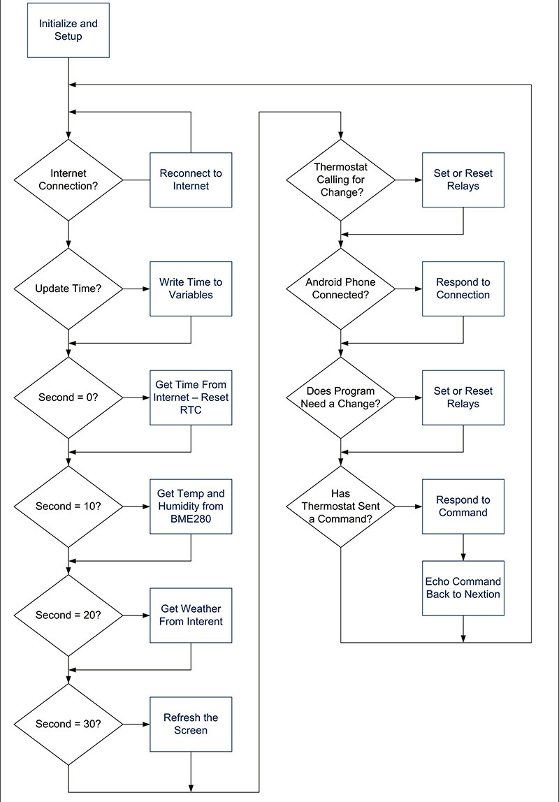
Figure 16. ESP32 program flowchart.
A portion of the program code creates a web server on the ESP32. Note in the definitions:
const char* ssid_serv = "ESP32-Access-Point";
const char* password_serv = "123456789";
The web server and a client is created in setup() with these lines:
// Set web server port number to 80
WiFiServer server(80);
WiFiClient client;
The function check_for_Client() is then used to see if a client has connected to our web server.
If you go to the settings on your Android phone or Windows PC and check the list of network connections, you should see one called ESP32-Access-Point. If you select it and enter the 123456789 password, it will connect to the thermostat.
After you’re connected, go to your web browser and enter the IP address 192.168.4.1 in the URL bar. A web page will be displayed that allows you to increase or decrease the temperature on the thermostat.
Note that this is a far cry from a truly Internet-accessible thermostat. It will only work when your phone is close enough to the thermostat to connect by Wi-Fi and you have selected the thermostat’s ESP32-Access-Point.
After making a temperature change, you’ll need to go back to your phone settings and reconnect to your normal router to regain Internet access.
Note that this section of the program is completely separate from where we connect to the Internet through your router to get the time and weather conditions for your area. For more information on getting the time from the Internet, see http://www.ntp.org. For information on getting the weather, see https://api.openweathermap.org.
Sending strings to the Nextion has a couple of requirements. To send the string “Thermostat – Heat” to text box t0 on page 0, it’s done like this:
sendThis = "page0.t0.txt=\"Thermostat-Heat\"";
writeString(sendThis);
Note the \” characters in the string to add the quote marks needed around the string. If a variable needs to be sent (like the temperature setting in the t1 text box on page 0), use:
tempstr = String(settemp);
sendThis = "page0.t1.txt=\"";
sendThis.concat(tempstr);
sendThis.concat("\"");
writeString(sendThis);
The writeString() function sends the string a character at a time using Serial2.write:
void writeString(String stringData)
{
for (int i = 0; i < stringData.length(); i++)
{
// Send one character at a time using Serial2.write, NOT Serial2.print
Serial2.write(stringData[i]);
}
Serial2.write(0xff); // Send three 0xff characters to denote end
Serial2.write(0xff);
Serial2.write(0xff);
}
That's a wrap. I do find my thermostat quite handy. I hope you will as well. NV
Parts List
Nearly everything in this Parts List can be obtained from eBay or Amazon. For screws and nuts, I stock a supply from Albany County Fasteners. All Electronics is a good source for hookup wire.
ESP32 development board, 38-pin
3.5 inch basic Nextion LCD display
Four-channel relay board
DS3231 real time clock mini board
BME280 temperature, humidity board
Power supply, 24 volt AC to five volt DC
Point-to-point wiring breadboard
Headers and header jumpers
3D printed project box and mounting bar
Various screw, nuts, hookup wire, solder
To connect this thermostat to the Internet for access anywhere in the world is beyond the scope of this article. It entails port forwarding on your router and a dynamic IP service with a domain name you obtain. You’ll also have to be up-to-date on firewalls and security since once you get on the Internet, there’s the potential to get hacked.
A Warning
Furnaces and air conditioning units are expensive, and repairs can be quite costly. Be sure you fully understand the wiring in your HVAC unit. The wiring of furnaces and air conditioners can vary greatly and standard color codes for wiring are not always used by installers. If you are unsure of the wiring and connections in your unit, contact an HVAC technician before connecting any circuit to your HVAC unit, including the one described in this project.
Downloads
What’s in the zip?
Code files
Schematic
Revised code