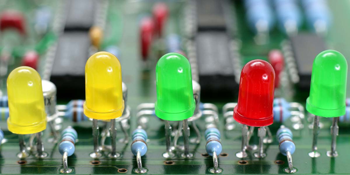
An LED is one of those product components that just has to work. If I look at my computer from across the room and don't see its LED winking back at me, I assume it's turned off; I never expect that the LED might have burned out. There's good reason for that: When operated within specs, an LED has a lifetime of 100,000 hours or more.
The key to maximizing LED life is limiting the current that runs through it. This is frequently done with a simple resistor whose value is calculated using Ohm's Law. This article reviews how to apply Ohm's Law to single and clustered LED circuits. I have also provided an Excel spreadsheet to simplify — and speed up — the process.
Single LEDs
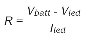
When computing the value of a current limiting resistor for a single LED, the basic form of Ohm's Law — V = IR — becomes:
where:
- Vbatt is the voltage across the resistor and the LED.
- Vled is the forward voltage of the LED.
- Iled is the forward current of the LED.
Figure 1(a) shows an example of a single LED circuit. Incidentally, Vbatt - Vled is the voltage drop across the resistor, and (Iled)2R is the power dissipated by the resistor. Calculating the power dissipation is a step that many people — hobbyists and professionals alike — tend to skip. So, what do you call a 1/8W resistor that needs to dissipate 1/2 W? Charcoal.
LEDs in Series
The equation above gets only slightly more complicated when you connect multiple LEDs in series. The voltage drop across the LEDs increases, reducing the voltage drop across the resistor. The current through the resistor (and the LEDs) remains the same:
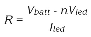
where n is the number of LEDs in series. Figure 1(b) shows an example with three LEDs connected in series. The voltage drop across the LEDs is three times the voltage drop of a single LED.
LEDs in Parallel
If you connect multiple LEDs in parallel, the current through the resistor increases (though the current through each LED remains the same). The voltage drop across the LEDs is unaffected, as is the voltage drop across the resistor:
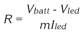
where m is the number of LEDs in parallel. Figure 1(c) shows an example with three LEDs connected in parallel. The current through the circuit is three times the current of a single LED.
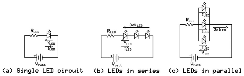
FIGURE 1. Simple LED circuits. (a) Single LED circuit. (b) LEDs in series. (c) LEDs in parallel.
LED Arrays
If you connect multiple LEDs in an array, you just need to combine the serial and parallel forms of the equations:
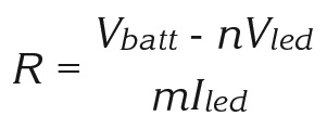
It's important that there are n LEDs (connected in series) in each of the m parallel branches of the circuit and that the LEDs all have the same Vled and Iled. Otherwise, all bets are off. Figure 2(a) shows four LEDs connected in such a way that the previous equation does not apply. Figure 2(b) shows one of several "proper" ways to connect four LEDs.
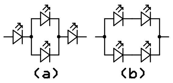
FIGURE 2. LED arrays.
Brightness Control
Brightness control is useful for gadgets that might be used under different ambient lighting conditions (outside/inside, night/day, etc.). This feature requires two resistors — one fixed (Rf) and one variable (Rv). Rf limits the current when Rv is at its minimum setting — usually 0Ω — which allows maximum current to flow through the LED. The value of Rf is calculated when Rv = 0:
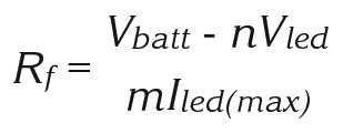
where Iled(max) is the maximum current you want through the LED.
Increasing the Rv setting adds resistance to the circuit, decreasing the current through the LED. When Rv is at its maximum setting, the minimum amount of current flows through the LED. The value of Rv is given by:
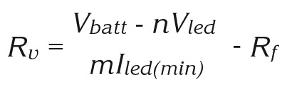
where Iled(min) is the minimum current you want through the LED.
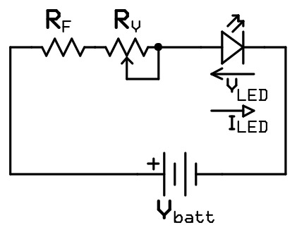
FIGURE 3. Brightness control.
Design Steps
There are four steps to selecting the proper current limiting resistor value(s):
- Using the desired operating characteristics and LED specs, solve the appropriate equations for the "ideal" resistor values.
- Select appropriate "real" resistor values. If the calculations specify a 132.27Ω resistor, the nearest "real" resistor values are 130Ω and 15 Ω (5% tolerance). Of course, you could select other values based on what you have on hand.
- Plug the values of the resistors you selected back into the calculations to see if they will satisfy the desired operating characteristics.
- Run through the calculations using the selected resistor values at the extremes of tolerance. A 150Ω resistor with 5% tolerance can range from 142.5Ω to 157.5Ω and will seldom be precisely 150Ω. Also, calculate the current draw of the circuit and the necessary power dissipation of the resistors.
Some folks don't go through any of these steps and just guess at a value. Most go through the first two steps, which is usually fine — as long as you don't operate too close to the LED’s limits, where tolerances can push you over the edge. By following all four steps, you can guarantee that your LEDs, at least, are operating safely and should last a good long time.
Multiple Iterations Are a Drag
Calculating the proper resistors for LED circuits is pretty simple. It takes just a few moments, even when going through all four design steps. That's no big deal, if you only have to do it once, but what if you want to see the effect of different resistors in the circuit? What if you have an array of LEDs and you want to determine the best way to hook them up? (Figure 4 illustrates four ways to connect six LEDs.) The calculations are still simple; you just have to do them a bunch more times. That gets tedious and that's exactly when people tend to make mistakes.
To beat the tedium and the mistakes that go with it, I've put together an Excel spreadsheet that performs all the necessary calculations — including looking up "real" resistor values. It's a real time saver!
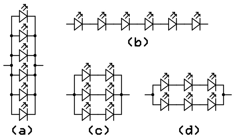
FIGURE 4. Ways to connect six LEDs.
Using the Spreadsheet
The spreadsheet (available in the downloads) is broken down into three sections. See a view of the spreadsheet in Figure 5.
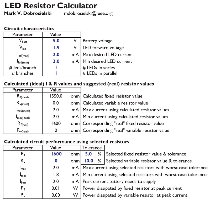
FIGURE 5. View of the spreadsheet.
The first section, Circuit Characteristics, is where you enter your circuit parameters. The second section, Calculated I & R Values and Suggested Resistors, calculates the needed resistor values and suggests "real" resistors to use in the circuit. The last section, Calculated Performance Using Selected Resistors, lets you plug in resistor values (the suggested values or values of your own choosing) and calculates LED currents, power supply currents, and resistor power dissipation. It also takes into account resistor tolerance. Note: Values in blue boldface are the only ones you should change. Plain black text shouldn’t be changed. NV
Downloads
What’s in the zip?
Resistor Calculator Spreadsheet