Sometimes I wonder which of my portable digital voltmeters I can trust — the B&K, Fluke, or Amprobe. Usually, they’re pretty close but it bugs me not knowing whether they are right on the nose.
Of course, I’m just being picky because I seldom need more than three or four digits of accuracy, but it sure would be nice to know the answer. Fortunately these days, there are a number of very accurate voltage reference circuits that you can build or purchase for a few dollars. A ready-to-use unit made by Agilent is shown in Figure 1.
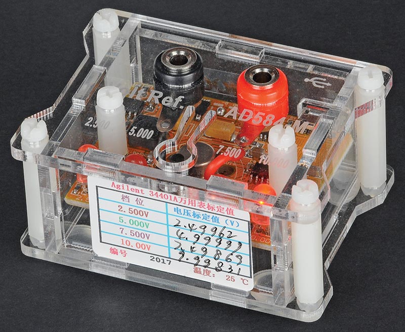
FIGURE 1. This $20 voltage reference module switches between 2.500, 5.000, 7.500, and 10.00 volts, and has a built-in USB rechargeable battery.
It puts out 2.500, 5.000, 7.500, and 10.00 volts and costs less than $20 on eBay. The actual precisely-measured voltages are recorded on the side label, good to six digits. The heart of it is a laser-trimmed Analog Devices AD584 voltage reference IC.
BUILD YOUR OWN
Or … you can build your own reference out of parts in your junk box. Figures 2 and 3 show a simple breadboard I made in an hour or so and the schematic. The only component I didn’t have on hand was the AD584.
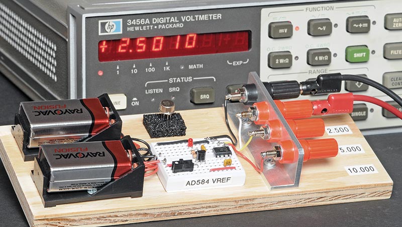
FIGURE 2. My DIY breadboard uses a laser-trimmed AD584 DIP; 2.500V output is accurate to 1 mV.
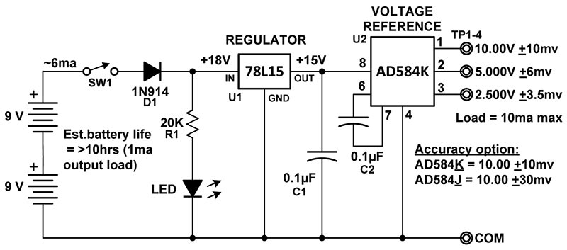
FIGURE 3. The schematic of the DIY breadboard can use two versions of AD584s, depending on the accuracy desired.
There are two grades of AD584s for hobbyists — J and K — which specify the accuracy of the outputs. J is +30 mV and K is +10 mV for their 10.00 volt outputs. The IC in the breadboard is the K version and the spec sheet lists a max error of +3.5 mV for the 2.500 volt output. You can see that the measured error is a lot less — only +1.0 mV. That’s one part in 2,500. Good enough for most measurements!
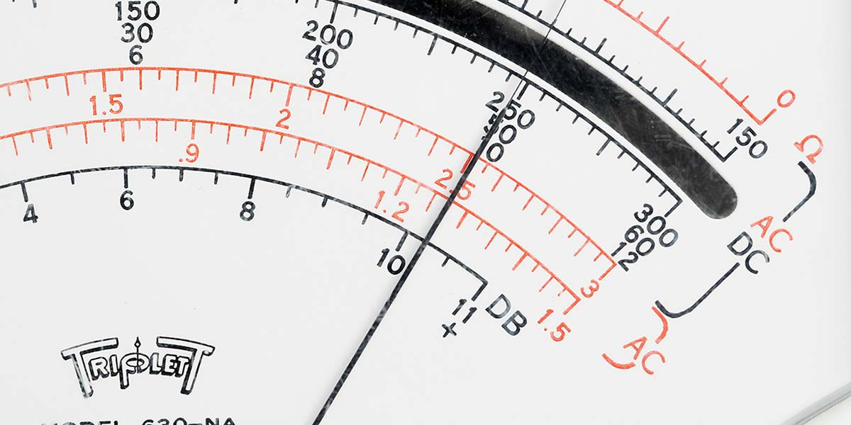
Just for fun, I dug out my old Model 630NA Triplett VOM with its cool anti-parallax mirrored scale to see what it would read. I magnified the image in Figure 4 and estimated the reading to be 2.488 volts.
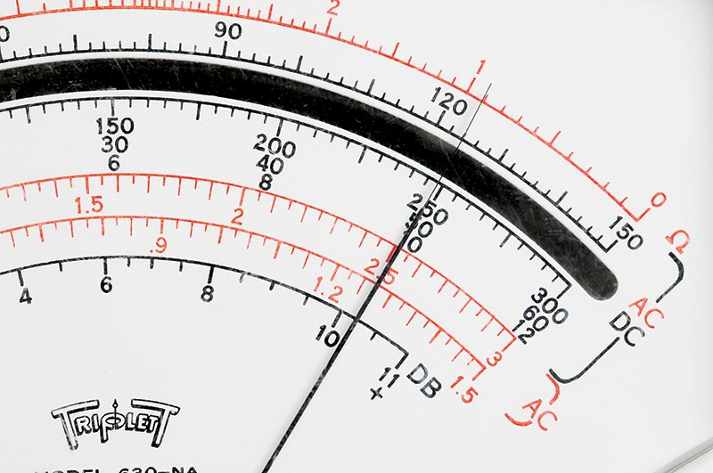
FIGURE 4. My vintage Model 630 Triplett VOM is accurate to within 1/2% after decades of hard use.
The manual for the meter stated the accuracy to be +1-1/2% of full scale. Bottom line: My Triplett was accurate to within 1/2% on the three volt range. Not too shabby for a meter as old as the hills!
EFFECT OF TEMPERATURE
I’m not going to discuss the effect of temperature on any of the voltage references I’ll be covering later in this article because that is a whole other subject itself. Plus, it’s been extensively covered in scientific studies. Temperature is a critically important parameter for many types of references, but the effects are quite small for hobbyist ICs.
For example, the 5.000 volt output of an AD584 only varies about +1.25 mV over the full industrial range of 0°C (32°F) to 70°C (158°F). If you are interested, I conducted temperature tests on an AD584 and the results are graphed in Figure A in the sidebar.
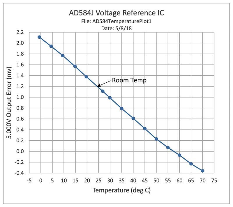
Figure A. Temperature plot of AD584 IC 5.000V output shows just 2.5 mV variation from 0°C to 70°C.
THE BLACK BOXES
Voltage references (or standards) in the past weren’t quite as small or inexpensive as the current ICs. They came in shiny black Bakelite housings that cost $40 in 1963 dollars. On a whim, I bought a brand new one (actually 39 years old) made by Eppley Laboratory on eBay for $50. It’s a real beauty. See Figure 5 for a size comparison to the modern AD584 DIP.
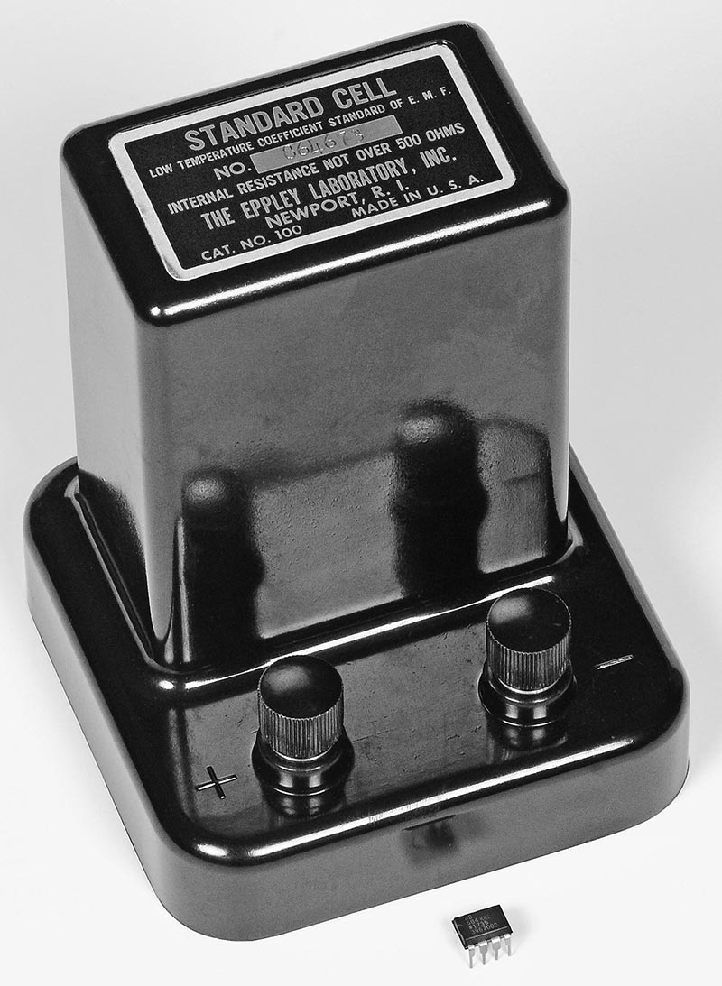
FIGURE 5. The Weston standard cell made by Eppley was the world’s primary voltage standard for over 70 years.
For almost 80 years (from 1911 to about 1990), these shiny black housings called Weston cells reigned supreme as the world’s primary and secondary voltage standards. Inside the housing was a simple glass vial filled with a bunch of high purity chemicals. Figure 6 shows one of the H-shaped vials with the chemicals at the bottom of each leg and filled with a liquid to just above the halfway point.
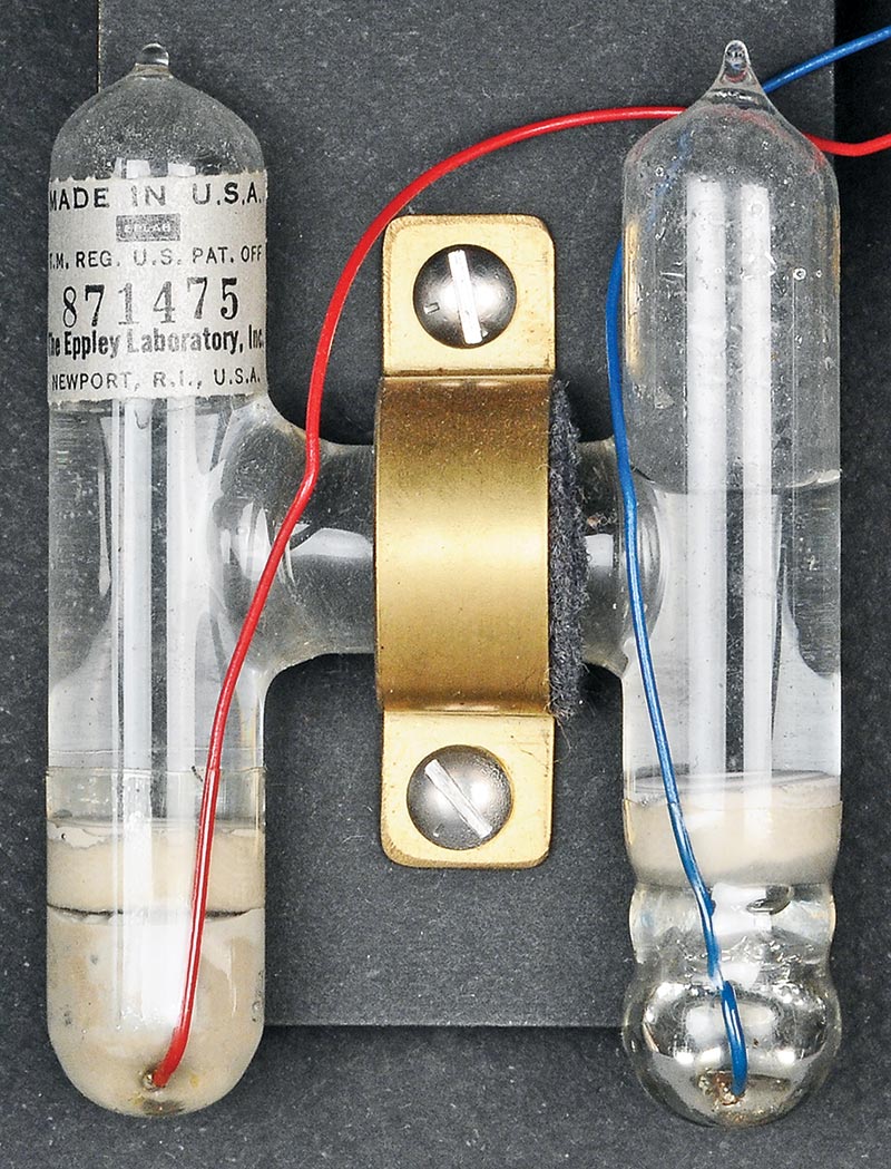
FIGURE 6. Inside the standard cell was a glass vial filled with chemicals that generate an accurate and stable voltage.
The chemicals included mercurous and cadmium sulfates, cadmium-mercury amalgam, and an electrode of shiny metallic mercury in the lower right leg. Platinum wires were used to bring out the voltage. The voltage was produced by the interaction between these chemicals and was a little over one volt; 1.0193 +.0002 volts to be exact.
Calibration labs in companies throughout the world used these cells to calibrate their voltmeters so the specifications of the electrical components and equipment they produced would be comparable for all users. The cells could only supply a few microamps (never more than 100 µa) when used. Typically, a laboratory potentiometer which used zero current from the cell when balanced, was used to generate other precise higher voltages to calibrate regular voltmeters.
There was an interesting caution in the cell’s operating instructions, “If a cell is shorted for 30 minutes, allow five weeks for it to recover to within 75 µV.” Lesson: Don’t short them or it’s a long wait.
TRACEABILITY TO NATIONAL BUREAU OF STANDARDS (NBS)
Although Weston cells were very stable, they still needed to be periodically checked against the nation’s super-accurate primary standard cells located at the National Bureau of Standards (NBS) in Washington, DC. Calibration labs and cell manufacturers would periodically send their cells to Washington and NBS would issue a certificate stating their precise measured voltages, good to one microvolt. The most stable type of cells — called “saturated” cells — were so delicate that they could not be tipped more than 45 degrees and had to be hand-carried all the way to and from NBS.
Cell manufacturers (like Eppley) would also maintain super-accurate saturated reference standards at their facilities, so the individual secondary cells they sold would be traceable back to NBS. Figure 7 shows the slightly wrinkled certificate that came with my Serial Number 864673 Eppley Standard Cell, certified to six digits. My secondary cell is the “unsaturated” type which is not sensitive to tipping and can be shipped in the regular mail.
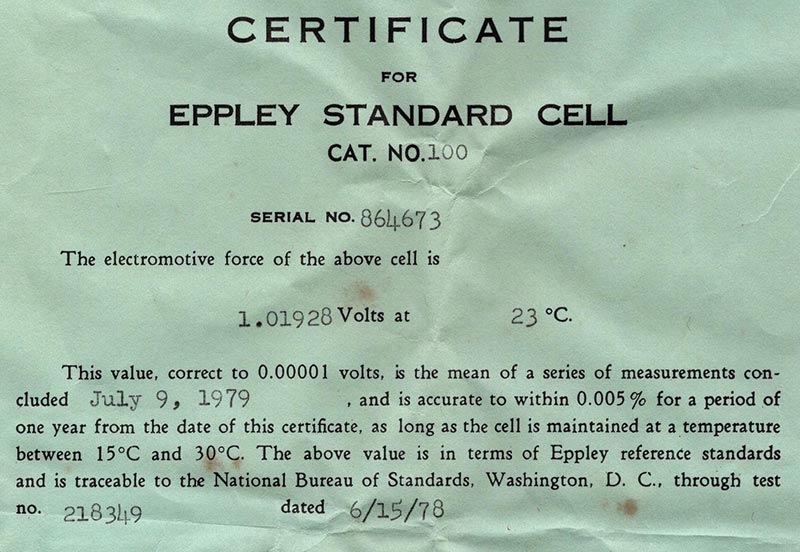
FIGURE 7. The manufacturer provided a calibration certificate along with each cell, good for one year.
NOTHING IS EVER EASY
Just owning the neat cell was not enough. Now, I wanted a “good” digital voltmeter to measure it, not my four-digit Fluke. I wanted to know exactly what the voltage was, to at least six digits or more. So, I checked the price of a refurbished 7-1/2 digit HP: $2,550. Gulp! What about eBay? How about a vintage 6-1/2 digit HP3456A for $99? Bingo! Check it out in Figure 8.
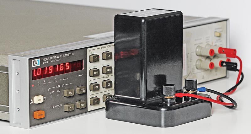
FIGURE 8. After 39 years, the voltage produced by this cell had only dropped 0.115 millivolts.
When it arrived, all the digits came on. However, pushing the Test button triggered an error of “-4.0000” which made me suspicious. So, I shorted the input terminals and it displayed all kinds of random digits, not the 0.000000 I expected.
After several days of taking it apart, measuring different voltages, and searching for people with the same problem, I found the answer. Not good! The older HP3456A voltmeters (like mine) had a design flaw. The three ROMs on Board #A4 tended to lose their memories after several years. I said a few words I can’t repeat.
After more research, I found some enterprising experimenters who had figured out how to replace the bad ROMs with more modern EPROMs, like 2716s or 2732s. It sounded like a fun challenge until I realized how many hours it would take to pull the chips, modify the address pins, download the files, and burn the new EPROMs. Even then it might not work and it would still need to be calibrated.
So … I caved in and bought another HP3456A from a regular test equipment house, for three times the money, and they calibrated it to the original specs. When it arrived, I checked to see if the ROMs had been replaced. Big surprise! Board #A4 had been completely redesigned by HP. No more three ROMS, just one big one. Hopefully, it won’t die like the others. Figures B and C in the sidebar show photos of HP’s board redesign.
HP redesigned their HP3456A voltmeter to replace three defective ROMs with one larger memory chip.
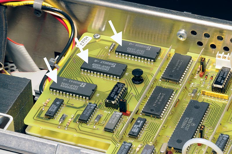
FIGURE B. Old HP3456A (serial #18467) with three defunct ROMs.
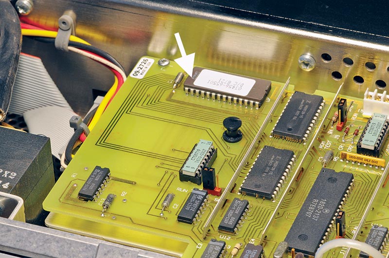
FIGURE C. Newer HP3456A (serial #19178) with redesigned board and a single ROM.
The final chapter to this story is better than the beginning. The fellow who sold me the original non-working unit gracefully refunded my $99 and told me to keep it as a door stop. All in all, it turned out for the better.
SERIOUS MEASUREMENTS
The Figure 7 cert for the 39 year old black beauty was 1.01928 volts. However, some Weston cells were known to lose a small amount of voltage over the years; about 30 µV/year: -30 µV x 39 years = -1560 µV (1.56 mV). Quite a bit!
With my newly acquired and calibrated HP3456A in hand, Figure 8 showed the actual loss and it was much, much less: 1.019280V - 1.019165V = 115 µV, i.e., a 0.115 mV loss in 39 years. Amazing! Maybe the lower loss was because of the brand-new condition of the cell and benign storage in a warehouse all that time. Who knows?
NEW TECHNOLOGY
Meanwhile, time marched on and new technologies popped up to challenge the Weston cell. In this case, it was the Josephson junction which proved to be 1,000 times more accurate and stable.
In 1962, a graduate student at Cambridge University named Brian Josephson derived a series of equations that postulated that two superconducting electrodes separated by a thin layer of insulation would create a special junction, now known as a Josephson junction. If an AC microwave signal was applied to the electrodes, pairs of Cooper electrons would tunnel through the insulator and create a tiny millivolt level DC voltage across the electrodes. The significance was that the value of the tiny DC voltage could be locked to the frequency of the microwave signal. In other words, a precise frequency would produce a precise voltage, every time.
A few millivolts was not a very useful calibration source, so developers fabricated an integrated circuit type structure that had an array of thousands of tiny junctions all in series, all adding up. It took 20,208 tiny junctions to produce one volt and almost 300,000 to make 10 volts. Figure 9 shows a microscopic view of an early one volt version. If you look closely, you can see the serpentine array of junctions, although the whole chip was only about 3/4” wide.
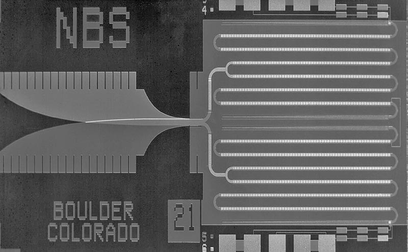
FIGURE 9. This highly magnified view of a superconducting Josephson junction array has 20,208 tiny junctions that generate 1.000000 volts. Photo courtesy of NIST.
Figure 10 is a view of a typical complicated laboratory setup using several cylindrical liquid helium dewars (pronounced do’-ers) to cool the integrated arrays to four degrees above absolute zero and provide the microwave power to the junctions.
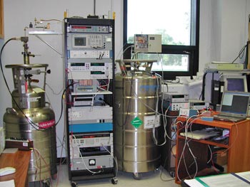
FIGURE 10. A primary voltage standard setup uses a tank of liquid helium to cool the Josephson junction array inside it to 40K. Photo courtesy of NIST.
Figure 11 is a very simplified diagram of the arrangement of the junctions, showing the flow of the precise microwave signal.
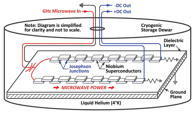
FIGURE 11. The value of the DC output of this simplified array diagram is locked to the frequency of the input microwave power.
Typical frequencies are around 75 GHz. Also for simplicity, the current-bias wires that determine the operating point of the array and polarity of the DC outputs are not shown.
Nowadays, 10 volt Josephson Voltage Standard (JVS) systems are located in over 70 facilities around the world, with new more compact and programmable systems being developed as we speak. However, all this development did not occur overnight. It took several decades before the first practical system was ready for everyday use — other than in a laboratory setting operated by PhD physicists.
If you want to know even more about Josephson junctions, there are quite a few scientific papers on the Internet. Check Wikipedia too.
BTW, if you have some extra cash laying around, you can buy a turnkey 10V programmable Josephson instrument from the NIST (National Institute of Standards and Technology) for the bargain price of $220,600. Or … you could build one in your basement.
ARE MY METERS ACCURATE OR NOT?
Finally, I checked all the voltmeters in my shop against a trimmed 5.00000V IC reference as shown in Figure 12.
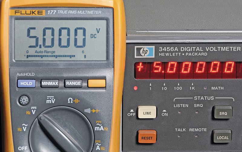
FIGURE 12. My Fluke DMM is right on the nose compared to a precision voltage source.
It was kind of anticlimactic because ALL the meters were right on the nose, including some analog panel meters. So now, I have no doubts about the accuracy of any DC voltage measurements I make in the future.
You might wonder why meters need to be periodically calibrated if they always seem to be right on. The answer is simple. In my youth, I briefly worked in the calibration lab of a large aerospace company and asked the supervisor the same question. He said “You may think they’re alright, but they could have been dropped or zapped out on the [production] line. You never know until you check ‘em.”
WRAPPING IT UP
While it might be fun to have your own world-class super-precision Josephson instrument in your basement, taking delivery of liquid helium each month might make the neighbors wonder.
In lieu of that, you can easily build or buy a perfectly good IC voltage reference and set your mind at ease about the accuracy of your meters. At least you’ll know for sure which meter you can trust. NV
Voltage Standards Parts List
| ITEM |
DESCRIPTION |
SUPPLIER |
| C1, C2 |
Capacitor, 0.1 µF, 50V |
Digi-Key, P4525-ND |
| D1 |
Diode, 1N914 |
Digi-Key, 1N914BCT-ND |
| LED |
LED, Red |
Junkbox |
| R1 |
Resistor, 20K ohm |
Digi-Key, 20KQBK-ND |
| U1 |
Regulator, 15V, 100 mA, 78L15 |
Digi-Key, MC78L15ACPFS-ND |
| U2 |
Voltage Reference, AD584K |
Digi-Key, AD584KNZ-ND |
| SW1 |
Switch, Slide, SPDT |
Digi-Key, EG1903-N |
| TP1-4 |
Binding Post, Pair, Red & Black |
Jameco 77691 (get three pair) |
| Breadboard |
Solderless Breadboard |
Jameco 2155452 |
| Battery (2) |
9V Alkaline |
Walmart |
| Holder (2) |
Battery Holder, 9V |
Digi-Key, BH9VW-ND |