A few months ago, I accepted a challenge: Design a way for people who can’t easily use a keyboard to create text for applications such as Word, OpenOffice, eBay, or Google via Morse code. Don’t let dots and dashes intimidate you! It takes only two fingers to create them, and learning to send Morse code proves easier than learning to receive it, which requires much practice.
A USB connection seemed to offer the best way to send information to a PC. However, I knew little about how USB devices worked and didn’t want to become a USB expert before I began to plan a solution. In this article, you’ll see how a $10 Cypress Semiconductor CY8CKIT-059 MCU board mimics a USB keyboard or other human interface device (HID), but without software drivers, code libraries, or special USB interface ICs.
The USB operations require only a few lines of C code because the MCU includes a full-speed USB function block. Although simplified, the USB connection still requires time and knowledge to set up and use. However, now you’ll have a working example to give you a head start. You’ll also learn about Morse code timing and how dots and dashes get interpreted in software.
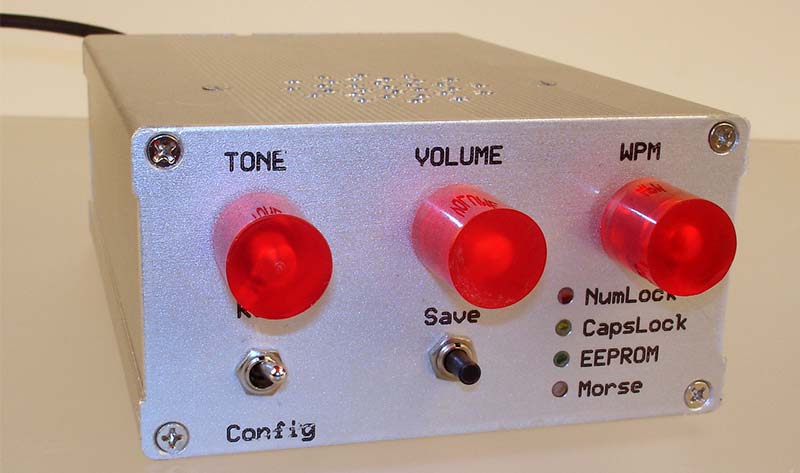
The final Morse-to-text interface (Figure 1) uses the Cypress board and a board I created to supply connectors and a small audio amplifier. For more information about the CY8CKIT-059 MCU board and the project files, see Resources.
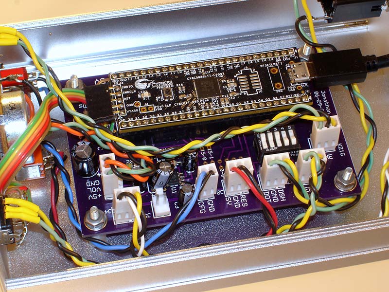
FIGURE 1. My Morse-to-text device uses a Cypress prototyping-kit board. A separate board underneath includes connectors for controls and an audio amplifier.
Start With a Plan
The Morse-to-text device I envisioned (Figure 2) would include ways to set the Morse code rate (words per minute), and adjust the frequency and volume of an oscillator so people could hear — if they wish to — the Morse code they send. A user may save these settings in the MCU’s EEPROM. The USB connection would provide power.
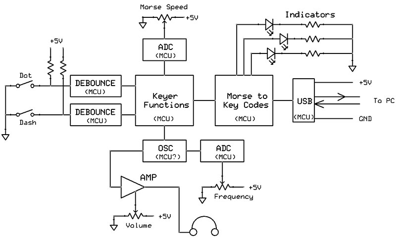
FIGURE 2. Preliminary circuit diagram for the Morse-to-text project.
The CY8CKIT-059 board provides 46 independent I/O pins for analog and digital signals. The MCU’s ARM Cortex-M3 processor runs the software which is written in C. I recommend you download the latest free Cypress “PSoC Creator” integrated development environment (IDE) software and try it with a simple project.
Each project already contains a main.c template for your code. Or, you can open the PSoC Creator archive file for this project, and examine and change my code and hardware configuration as you choose.
The Cypress chip includes programmable universal digital blocks (UDBs) that let you create your own internal functions such as pulse-width modulators, oscillators, multi-bit registers, and USB ports. The current PSoC Creator IDE catalog lists over 200 ready-to-use analog and digital components.
The PSoC Creator gives these components generic names such as Timer_1 and Register_4, but you can rename them to better describe their function. The PSoC Creator IDE will then use your names when it creates the application programming interface (API) functions for those components. The screen image in Figure 3 shows a PSoC project and the IDE sections.
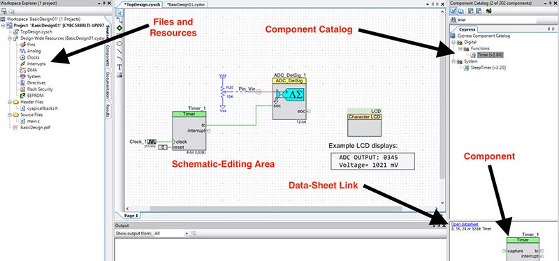
FIGURE 3. A typical project created with the PSoC Creator software.
Run Simple Tests First
I soldered pins on a Cypress board, put it in a solderless breadboard, connected it to my PC with a USB cable, and started the PSoC Creator IDE. Next, I put two digital input pins in the IDE’s schematic editing area and changed their default pin names to DashIn and DotIn. I then assigned the DashIn and DotIn signals to physical pins and added pins to the schematic for external LEDs that might help during debugging.
Movies and old photos show people using a “straight key” to create dots and dashes. The telegrapher determined the length of the dots and dashes, and how to properly space them; a skill honed over time. Today, people such as ham radio operators use an electronic “keyer” and “paddles” to send code.
Paddles supply two normally-open switch contacts: one for dashes and the other for dots. The keyer circuit properly times the dot and dash periods, and sends “perfect” Morse code at a rate hams can adjust. Several YouTube videos demonstrate how paddles operate. A paddle reduces hand motions and fatigue when people send a Morse code message. You can buy Morse code paddles or build your own.
As a test, I used two normally-open pushbuttons to separately ground the DotIn and DashIn pins. These pushbuttons let me quickly test the connections and the MCU’s response via a simple keyer program placed in the so-far “empty” main.c folder within the PSoC Creator IDE.
DotPeriod = 100;
DashPeriod = 3 * DotPeriod;
for(;;)
{
if (DashIn_Read() ==0) /If DashIn grounded
{
Dash_Write(1); /Turn on Dash LED
CyDelay(DashPeriod); /Create dash for 3X Dot period
Dash_Write(0); /Turn LED off
CyDelay(DotPeriod); /Short delay; one Dot period
}
if (DotIn_Read() = = 0) /If DotIn grounded
{
Dot_Write(1); /Turn on Dot LED
CyDelay(DotPeriod); /Create a dot
Dot_Write(0); /Turn LED off
CyDelay(DotPeriod); /Short delay; one Dot period
}
}
When I run the program and press the Dot button, the Dot_Write LED flashes. When I press the Dash button, the Dash_Write LED turns on for three times longer than the Dot_Write LED.
What happens if I press both buttons simultaneously? I would see the LEDs flash a dot, a dash, a dot, a dash, and on and on. Alternating dots and dashes created this way have the name iambic keying.
Press and hold either button and you’ll get a continuous output of dots or dashes. To send the word “hi” for example (.... ..), press and hold the dot button and the code creates four dots in a row. Briefly release the dot button for the space between characters and then press it again to get two dots for the “i.”
With the short section of software previously shown, the MCU acts like an electronic keyer. That’s a good start, and this continuous loop provides the core of the Morse-to-text program.
Time Your Morse Code
My device won’t “read” Morse code as you would hear it on a radio or in a movie. By design, the software will “know” a signal on the DotIn pin means a dot and only a dot; likewise for the DashIn input. The MCU only needs to keep track of the order in which it detects a logic 0 on these two input pins and the times between them.
Amateur radio operators follow five rules which are listed next and shown in Figure 4 for good Morse code communications.
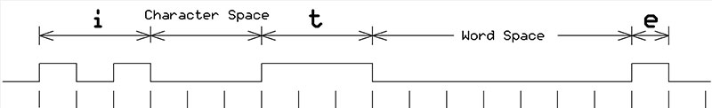
FIGURE 4. Timing relationships for accurate Morse code transmissions. The dot period serves as the reference for all measurements.
This project adheres to them.
- The dot period serves as the reference for all time measurements.
- A dash period is three times as long as a dot period.
- Space between dots and dashes in a single character = 1 dot period.
- Space between characters in a message = 3 dot periods.
- Space between words in a message = 7 dot periods.
The MCU software shown earlier always adds a “silent” dot period after every dot or dash. Thus, according to the requirements listed, the time between characters requires at least two additional dot periods, and the time between words requires at least six additional dot periods.
So, to properly space Morse code characters and words, my software needed two timers. I named Timer_2X for the period between characters, and Timer_6X for the period between words. The PSoC Creator has functional blocks for down counters that can trigger an event such as an interrupt when a count reaches zero. I found counters easier to set up than PSoC timer blocks, but I kept the name “Timer.” The PSoC Creator software lets you examine my counter setup and use conditions.
Counters Use Interrupts
When Timer_2X or Timer_6X cause an interrupt, the MCU runs a short interrupt-service routine (ISR) as shown next and then returns to the main program. The PSoC MCU doesn’t require a programmer to work with interrupt registers or multi-bit interrupt settings common in other controllers. Instead, the PSoC Creator IDE automatically creates an “empty” ISR for each interrupting device. You simply add the ISR code as shown here:
CY_ISR( Timer_2X_Handler )
{
Timer_2X_ReadControlRegister(); //Clear interrupt signal
keyFlag = 1; //Set keyFlag to 1
} //return to program
CY_ISR( Timer_6X_Handler)
{
Timer_6X_ReadControlRegister(); //Clear interrupt signal
keyFlag = 2; //set keyFlag to 2
charindex = 64; //Reset charindex to 64
counter = 32; //Reset counter to 32
} //Return to program
The diagram in Figure 5 shows the Timer_2X and Timer_6X circuit that uses two Control Registers (latches) to start or reset the timers simultaneously. The Sync function simply aligns clock edges with the PSoC system clock that governs internal operations. Because ISRs “steal time” from the main processor, try to keep ISRs short.
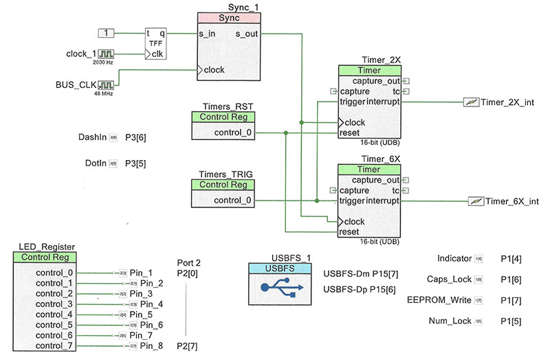
FIGURE 5. PSoC Creator schematic diagram for the Timer_2X and Timer_6X blocks. The USBFS block gets used later for PC communications. The DashIn and DotIn pins connect to no circuit blocks. The software simply tests their input states for logic 0 or logic 1.
The flowchart in Figure 6 represents the largest section of software in which the highlighted portions represent keyer functions described earlier. Prior to running those operations, the software tests for new information sent from the PC, and the MCU sends the PC any new data.
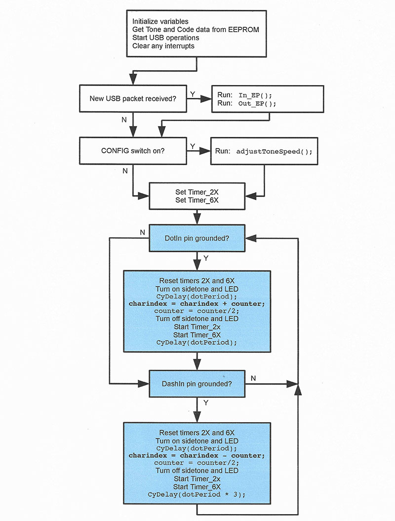
FIGURE 6. Flowchart for the largest section of C code for the PSoC MCU.
These early sections of the program get, or set, variables and a person’s preferred code speed, the Morse code tone, and its volume.
The diagram in Figure 7 illustrates how the two timer operations affect Morse code interpretation.

FIGURE 7. Timing diagram for “it e” sent as Morse code, and the operation of Timer_2X and Timer_6X. An asterisk “*” indicates a counter triggered an interrupt, and an “S” indicates the MCU stopped a timer before it caused an interrupt.
In this example, someone sends the word “it” followed by the letter “e.”
- Step 1: On the falling edge of a dot or a dash, the MCU sets the initial values for Timer_2X and Timer_6X and starts both.
- Step 2: On the rising edge of a dot or dash, the MCU stops the counters if they haven’t already reached 0 and causes an interrupt.
After the last dot for the letter “i,” Timer_2X decrements to 0 and interrupts the MCU to indicate the end of the Morse code letter “i.” The MCU then finds the keyboard code for “i” and sends it to a PC. The rising edge of the dash for letter “t” halts Timer_6X so it can’t decrement to 0 and does not cause an interrupt.
At the falling edge of the letter “t” dash, the MCU reloads and restarts the counters. After two dot periods, Timer_2X interrupts the MCU, which then looks up the code for “t” and sends it to a PC.
After six dot periods, Timer_6X has decremented to 0 and causes an interrupt that indicates the end of a word. The MCU sends the PC the code for a space to separate a word.
You can modify the calculations for both timer values if you want the interrupts to occur closer to the end of the two-dot period or the six-dot period. I felt comfortable with the standard time relationships described earlier.
I configured the counters as “one-shot” devices, so they stop when their count reaches 0. They don’t automatically reload a count value and restart a down count. The MCU must reset and restart them.
The flowchart for the USB operations (Figure 8) highlights the EP_In operations that decide what to send the PC via the USB connection. Based on the value of the keyFlag set in the ISRs for Timer_2X and Timer_6X, the PC receives either a letter or symbol code, or a character “space” to separate words.
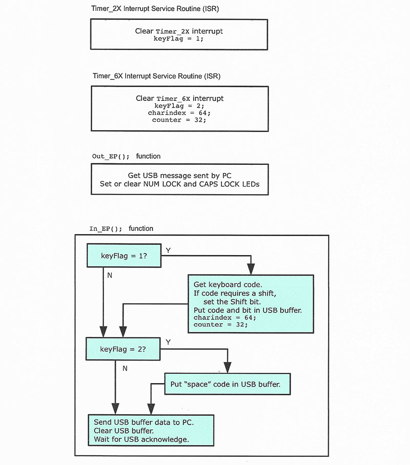
FIGURE 8. A flowchart that shows the use of the keyFlag value set by the Timer_2X or Timer_6X interrupt subroutines.
The PSoC schematic diagram (Figure 9) for most of the circuit shows connections between the Cypress CY8CKIT-059 board and signals that go to or from other components, connectors for inputs and outputs, and an SMT amplifier chip and its components.
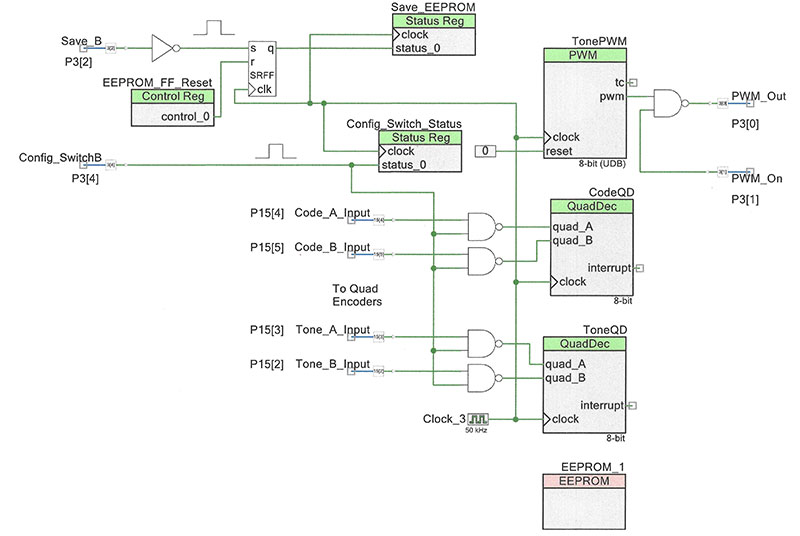
FIGURE 9. PSoC Creator circuit diagram for the quadrature-encoder interface blocks, the EEPROM, the tone generator, and the configuration-switch input block.
The circuit diagram for the main circuit (Figure 10) provides connection and component information for controls and LEDs external to the CY8CKIT board. The circuit includes the low power audio amplifier for the Morse code tone signal.
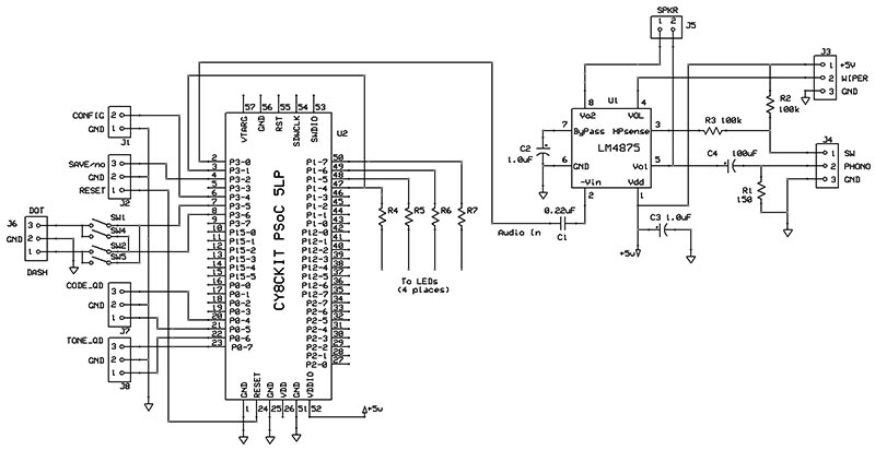
FIGURE 10. Main circuit diagram for the two circuit boards.
But It Looks Like a Keyboard
The Cypress board includes two USB connectors; one is for a cable that connects the board to a host PC for development work and programming. You would disconnect this cable after you run any final tests or put a program in EEPROM. A second USB connector links the board to a PC that will receive the text converted from Morse code.
As I worked on the main portion of the program, I learned how to use the Cypress PSoC USBFS block, shown in an earlier diagram. This full-speed (12 Mbits/sec) USB port in the PSoC MCU lets an application connect to a PC’s USB port.
To help designers, Cypress provides instructions and examples that help, but it still took me many trial-and-error tests to get the USBFS block to operate as I wanted. I found some instructions in Application Note AN58726 confusing, and spent a lot of time getting “USB report” information properly set up. After I crossed that barrier, the USB connection worked flawlessly.
To learn about how to create a USB interface with the CY8CKIT board, I recommend you start PSoC Creator and open my archived project. Click on the USBFS block to view the USB setup information. Then, read Cypress application notes AN57473 and AN58726, and review my settings. Feel free to use the latter as the basis for any project you wish. Refer to the Resources.
I won’t describe the complete USB-HID communication process because I needed only two simple USB-related functions: In_EP and Out_EP. The initials EP stand for “endpoint” which is simply a buffer on a connected device. An In-endpoint buffer holds data going into a USB host (usually a PC) and an Out-endpoint buffer holds information sent to a device by a host. I adapted code from Cypress examples so my circuit “looks like” a keyboard when it connects to a PC.
As the MCU detects dots and dashes, it adds to or subtracts from an array index that will point to a letter’s or symbol’s equivalent PC keyboard code. After Timer_2X triggers an interrupt, the code detects keyFlag=1, and uses the array index to get and send the keyboard code via the USB connection.
The PC keyboard codes are not ASCII values. The array-use details are straightforward, and many ham radio Morse code reader programs work this way to “home in on” a character value. You can find code reader software examples via a Google search.
Each PC keyboard key has one eight-bit code. The lowercase letter “h,” for example, has the code 0x0C (hexadecimal). There’s no code for an uppercase “H.” When you press Shift, it sends its own code (0x02 for the left-side Shift and 0x20 for the right-side Shift). These and other keyboard codes modify how the PC handles the information it receives.
A Bit More Hardware Please
So far, the breadboarded interface worked well, but I needed a way for users to set a comfortable Morse code rate, a side tone for audible dots and dashes, and the tone volume. I had planned to use eight-bit analog-to-digital converters (ADCs) and potentiometers for each setting, but opted for incremental or quadrature encoders instead.
The Cypress MCU has built-in quadrature-encoder functions. Figure 11 shows the second part of the PSoC based design. After people adjust the rate and frequency, they can save them in the MCU’s EEPROM. The software automatically recalls them when first powered or reset.
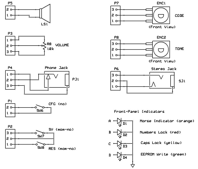
FIGURE 11. Front-panel and control wiring for the Morse-to-text device. Use a simple on-off switch for the RUN-CONFIG control. The SAVE input uses a momentary normally-open pushbutton. The RESET connection exists on the PCB, but I didn’t use it.
The TonePWM block shown earlier in Figure 8 creates a square wave for the Morse code side tone. That’s not an ideal sound, but it suffices. Each dot or dash gates a PWM output to an external audio amplifier created with an LM4875 IC and a few components. This amp can drive a small speaker, headphones, or an earpiece.
In the RUN position, the front-panel switch causes the MCU to use default settings (if any) previously saved in EEPROM. The CONFIG mode lets you vary the Morse code speed and tone frequency. To save these new settings, a press of the SAVE button puts them in the EEPROM. They become the new default values.
You can operate the device in either the RUN or CONFIG mode. A RESET button lets you reset the MCU, but it doesn’t alter data saved in the EEPROM.
The circuit includes a five-position DIP switch. Close switches 1 and 4, or close switches 2 and 5. These settings reverse the dot-dash sides of the paddles. I prefer dot on the left-side paddle (my thumb) and dash on the right (my index finger), but you can choose whichever setting suits you. Switch 3 does nothing.
Add Shift and Enter
How does Morse code handle keyboard functions such as SHIFT, ENTER, CAPS, BACKSPACE, INSERT, DELETE, and TAB? You could create unique strings of dots and dashes to perform them. Rarely used Morse codes for parentheses, exclamation marks, semicolons, and colons exist, and you could adopt these to perform the format operations described above. Perhaps a future design will take this approach.
For now, though, I bought a Max Keyboard Falcon-20 4-by-5 keypad and programmed the keys for the functions noted above. The manufacturer provides a PC application that lets me assign any PC-keyboard button to any button on the 20-key pad.
I arranged the keys so that the same one or two fingers on either hand control the same functions. The bottom row of four keys provides ENTER, SHIFT, SHIFT, and ENTER keys in that order, and the next row up has BACKSPACE, CAPS, CAPS, and BACKSPACE keys. Thus, an index finger on either hand always presses the ENTER key and the middle finger always presses the SHIFT. Unused keys on each keyboard “half” let me add other operations as needed.
The final design includes four LEDs: a yellow LED for CAPS LOCK; a red one for NUM LOCK; and a green LED that flashes three times after the MCU has saved current settings in its EEPROM. An optional orange LED gives you visual dots and dashes. It helped when I ran tests. NV
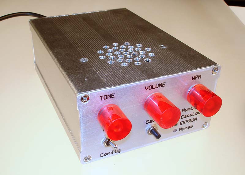
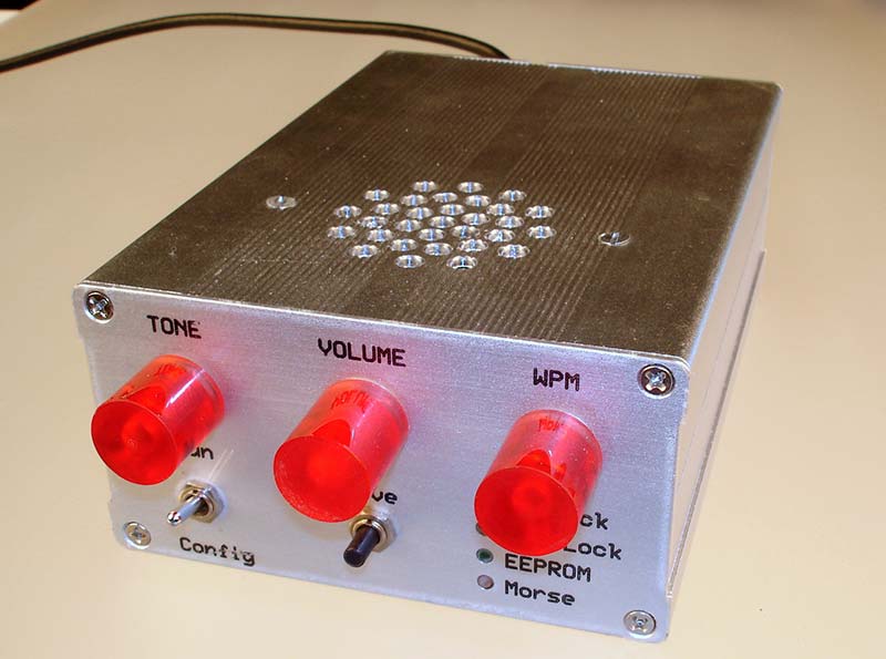
The completed unit.
Note: PSoC is a trademark of Cypress Semiconductor.
Resources
For more information about a PSoC application, visit https://www.nutsvolts.com/magazine/article/create-an-led-sign-controller.
The two download packages for this article include:
- Complete circuit diagrams, flowcharts for the software, the C language code in a plain-text file, and a parts list. This package also provides a PSoC Creator archive folder that holds the complete project information for the Cypress microcontroller and PSoC Creator software I used.
- The second package provides the ExpressPCB design files and Gerber files for the PCB. The entire project is open source. Use it or parts of it as you wish.
https://www.cypress.com/documentation/development-kitsboards/cy8ckit-059-psoc-5lp-prototyping-kit-onboard-programmer-and.
For the newest PSoC Creator software, visit https://www.cypress.com/documentation/software-and-drivers/psoc-creator-software-archive.
PSoC 5LP Prototyping Kit Guide
https://www.cypress.com/file/157971/download.
“Getting Started with PSoC 5LP,” AN 77759
https://www.cypress.com/documentation/application-notes/an77759-getting-started-psoc-5lp.
For a list of standard USB-keyboard codes, visit https://gist.github.com/MightyPork/6da26e382a7ad91b5496ee55fdc73db2.
“USB HID Basics with PSoC 3 and PSoC 5LP,” AN57473, Cypress Semiconductor, https://www.cypress.com/documentation/application-notes/an57473-usb-hid-basics-psoc-3-and-psoc-5lp.
“PSoC 3 and PSoC 5LP USB General Data Transfer with Standard HID Drivers,” AN82072, Cypress Semiconductor,
https://www.cypress.com/documentation/application-notes/an82072-psoc-3-and-psoc-5lp-usb-general-data-transfer-standard-hid.
“USB HID Intermediate with PSoC 3 and PSoC 5LP,” AN58726, Cypress Semiconductor,
https://www.cypress.com/documentation/application-notes/an58726-usb-hid-intermediate-psoc-3-and-psoc-5lp.
www.maxkeyboard.com
“Universal Serial Bus, Device Class Definitions for Human Interface Devices (HID),” Ver 1.11, June 27, 2001. USB Implementers Forum, https://www.usb.org/document-library/device-class-definition-hid-111.
“Human Interface Device Tutorial, AN249,” Rev. 0.5, March 2011, Silicon Laboratories, https://www.silabs.com/documents/public/application-notes/AN249.pdf.
“USB Keyboard Using MSP430 Microcontrollers,” Application Report SLAA514, December 2011, Texas Instruments,
www.ti.com/general/docs/lit/getliterature.tsp?baseLiteratureNumber=slaa514.
Downloads
What’s in the zip?
Code Files
Schematics
Gerber Files