Dealing with RF circuits is daunting for most experimenters. It is tricky and a bit frustrating if you build your own RF circuits. Now you don’t have to — thanks to the many available wireless modules. These units are designed for short-range projects, and most feature FSK (frequency-shift keying) data transmission in the industrial-scientific-medical (ISM) bands. Recently, I tried out some modules to implement a remote control off-on circuit. It was easy to put together and an immediate success.
The Radio Modules
The modules I used are made in the UK by a company called Radiometrix. They are available in the US from their distributor, Lemos International. The transmitter module TX3A operates in the ISM band at 914.5 MHz. It uses FSK modulation and can take data at a rate up to 64 kbps. The nominal output power is 0 dBm or 1 mW. That’s not much power, but good enough for a range of 25 to 100+ meters depending on the environment. It can operate from a DC voltage in the 2.2 to 16 volt range.
The matching receiver RX3A is a standard superhet with a sensitivity of up to -107 dBm. It operates from DC in the 2.7 to 16 volt range. The modules have pins that conveniently plug into a standard breadboarding socket.
Figure 1 shows the transmitter circuit. I used a 555 timer to generate a 480 Hz rectangular wave to modulate the transmitter.
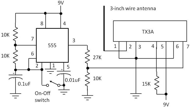
FIGURE 1. Transmitter diagram with 555 timer IC and Radiometrix TX3A transmitter module.
The voltage divider at the output of the 555 is used to reduce the input to the transmitter to less than 2.5V as required. The antenna is a three inch vertical wire. The whole thing is powered by a 9V battery.
The 15K resistor is a pull-up that provides an enable signal to the module. A standard slide switch turns the 555 on and off as desired. When the contacts are closed, the oscillations are stopped as the timing capacitor is shorted. At this time, the remote device will be off. Opening the switch contacts starts the oscillation, and the remote circuit will turn on.
The receiver circuit is shown in Figure 2. I used a nine volt battery to power the receiver. The antenna is also a three inch vertical wire.
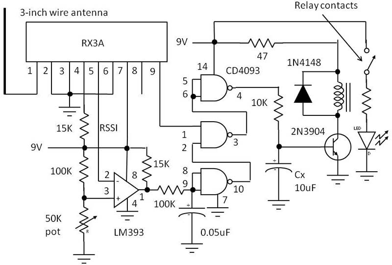
FIGURE 2. Receiver diagram with Radiometrix RX3A receiver, control logic, and control relay.
The 15K resistor is a pull-up that provides an enable signal to the module. The receiver simply recovers the data sent by the transmitter. The data appears at pin 9 of the RX3A and drives a logic circuit using CD4093 quad NAND Schmitt trigger gates with an LM393 comparator.
This circuit keeps the relay from turning on if there is no data. Even with no data, the output signal on pin 9 is noise that is of a sufficient level to keep the relay on. The received signal strength indicator (RSSI) signal on pin 5 is used to alert the availability of real data.
The clean data signal at pin 4 of the CD4093 is used to drive a 2N3904 transistor switch that operates a relay. The 47 ohm resistor was selected to drop the unnecessary voltage to the five volt relay coil. You may need a different value for the relay you select. The 1N4148 diode protects the transistor from a voltage spike when the relay coil turns off. The data pulses will turn the relay on, closing its contacts to actuate something else. The LED is used to check the contact closure.
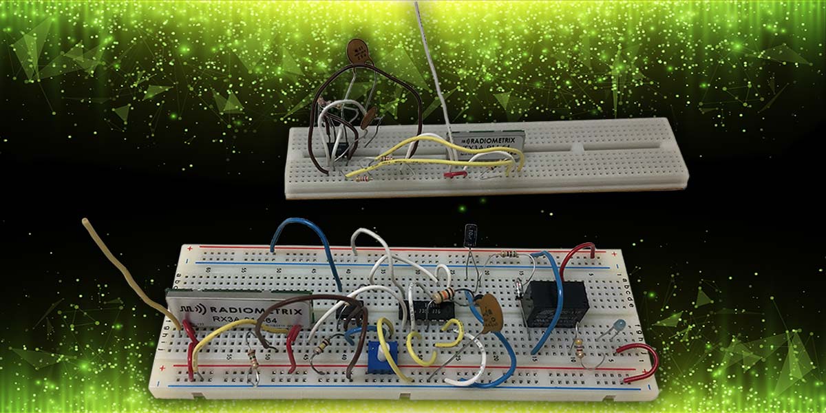
Figure 3 shows the breadboarded transmitter and receiver. They are messy, but they work, and I can rebuild them in a neater more compact way now that I know they work.
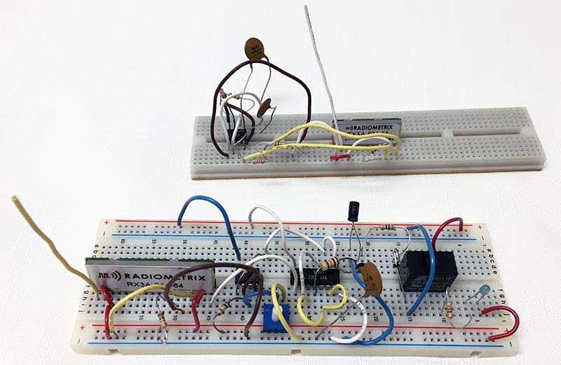
FIGURE 3. The messy but fully operational breadboarded transmitter and receiver. The nine volt batteries are not shown. Note the Radiometrix modules. The vertical wires are the antennas. The relay is the black box on the right of the receiver in the foreground.
To test the system, separate the transmitter and receiver by several feet or more (like across the room from one another). Apply power to both. The off-on switch at the transmitter should be closed to prevent data from being generated. The relay should be off at this time as determined by the LED operated by the contacts. If the relay is on, that means some noise is getting through. Adjust the 50K potentiometer until the relay and LED turn off.
Turn on the data by opening the switch at the transmitter. The LED should turn on. Turn off the data by closing the switch. The LED should go off. If not, adjust the 50K pot until it does. Repeat this process until you get a setting for the pot that works best.
Turn off the power to avoid running down the batteries. The receiver is fairly power hungry and eats nine volt batteries pretty fast. So, unplug the battery if you are not using the receiver. One possible solution is to use four AA cells to give six volts. This supply will last longer. You may need to trade the 47 ohm relay resistor for one of 22 ohms to ensure relay pull-in. Plus, the 50K pot will need readjustment.
How It Works
You would think that a steady 480 Hz recovered square wave from the 555 would simply turn the relay off and on at that rate. However, that’s not the case. The relay is a mechanical device and cannot switch off and on that fast. What happens is that capacitor Cx averages the pulses into a DC voltage that turns on the 2N3904 transistor. That holds the relay on. When the signal pulses stop, the average DC on Cx drops to zero, turning off the transistor and relay.
A key point here is that you should select the relay based on what kind of load it will switch. The relay I chose can handle a standard 120 VAC 60 Hz circuit with up to two amps of current. I operated a remote 60 watt lamp. Choose your relay contacts to operate whatever the remote controlled device is.
In experimenting with range, I found it amazingly long. All I needed was a couple hundred feet, but there was a clear path from transmitter to receiver. If there are obstacles like trees, fences, or houses in the way, the signal could be blocked. The signal can penetrate walls, but the walls do greatly attenuate the signal and shorten the range. You will need to experiment with your setup to see what works. NV
Parts List
Transmitter
TX3A transmitter module from Radiometrix
555 timer IC
10K ohm 1/4 watt resistors (3)
15K ohm 1/4 watt resistor
27K ohm 1/4 watt resistor
0.01 µF disc capacitor
0.1 µF disc capacitor
SPST slide switch
Receiver
RX3A receiver module from Radiometrix
2N3904 NPN transistor or equivalent (e.g., 2N2222, etc.)
1N4148 silicon diode
LED (light emitting diode); common type
LM393 dual comparator
CD4093 CMOS quad two-input NAND Schmitt trigger gates
Relay 5V coil with contacts to match desired load
47 ohm 1/4 watt resistor
470 ohm 1/4 watt resistor
1K ohm 1/4 watt resistor
10K ohm 1/4 watt resistor
15K ohm 1/4 watt resistor
100K ohm 1/4 watt resistor (2)
50K ohm potentiometer
0.05 µF disc capacitor
0.1 µF disc capacitor
10 µF electrolytic capacitor
The Radiometrix modules are available from Lemos International at www.lemosint.com. Go to the Radiometrix website at www.radiometrix.com and print out the datasheet and app notes on the TX3A and RX3A.