Let's face it — if this article was titled, “Thermal Analysis,” you might put off reading it! But choosing a heatsink? Everybody understands what that’s all about, right? To make that choice, you have to do a little thermal analysis (gotcha!), but if you can do Ohm’s Law, you already know how!
Introduction
Any time current flows through a conductor, energy must be dissipated in the form of heat with the power — Pd = I2R. (For superconductors, R = 0.) It’s also true that when a voltage drop and current flow exist at the same time — Pd = V x I. Heating from current flow is present everywhere in an electrical circuit, but by far most of the heat is generated within electronic components.
An electrical component gets rid of heat by transferring it to the surrounding air. The heat can pass directly to the air from the surface of the component or a heatsink can be used. Either way, if too much heat builds up, the component can be damaged. Most of the time, only a few components have a heavy heat load — pass transistors, driver ICs, solenoids. Nevertheless, you’re the circuit designer, so you’re responsible for figuring out which components need to be cooled and how to do it.
Heat Transfer = Ohm’s Law
The flow of heat follows rules that are remarkably similar to those that govern the flow of electric current. As Figure 1 shows, temperature difference (ΔT) takes the place of voltage and heat flow (P) takes the place of current.
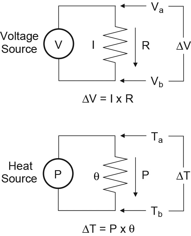
FIGURE 1. Basic heat transfer is very similar to Ohm’s Law for resistance.
The new symbol θ — represents thermal resistance, analogous to electrical resistance; something you’re already quite familiar with. The fundamental equation for heat transfer looks just like Ohm’s Law:
ΔT = Ta - Tb = Tab = P x θab
T acts as a “heat voltage,” P like a “heat current,” and θab as “heat resistance.” T is usually specified in °C and P in watts. θ is specified in °C/W, which looks a little strange until you consider that resistance is really “volts per amp.” As more power flows through a thermal resistance, the temperature drop across it increases; ‘a’ and ‘b’ are two physical locations and the heat flow occurs between them.
What happens if several different thermal resistances are encountered by the heat flow? Just like electrical resistance, the thermal resistances sum in series. The total thermal resistance is θ = θ1 + θ2 + ... + θn. Temperatures at the junction of the thermal resistances can be calculated just like voltages in a voltage divider, as shown in Figure 2. (Yes, there are parallel heat circuits, too.)
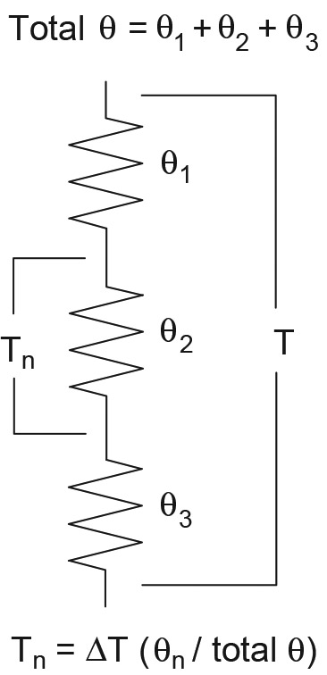
FIGURE 2. If the heat must flow through a sequence of materials, then the thermal resistance of each material sums together, just as electrical resistors in series do.
The discrete thermal resistances in series represent the flow of heat through a series of materials. For example, in winter, the heat in your house flows first through the air inside, then through the inner wall, through the insulation, and through the outer wall to the ambient air outside. The larger the total thermal resistance, the less heat is lost for any given combination of inside and outside temperatures. Conversely, if you like the temperature high or it gets colder outside, you’ll lose more heat because ΔT is larger.
How Much Heat Does a Component Generate?
Power dissipation in resistors is pretty easy to calculate, but what about semiconductors and ICs? For components where the resistance isn’t known or changes — such as for an FET — you can’t easily use I2R. In these cases, use V x I. And that works for resistors, too! Table 1 shows a list of equations for heat generation in some common electronic components.
- Resistor — Pd = I2 x R = V2 / R = V x I
- Diode, SCR, or TRIAC — Pd = Vf x Iavg where Vf is forward voltage drop and Iavg is average forward current
- Transistor — Pd = VCE x IC (bipolar) Pd = VGS x ID (FET)
- Inductor, Capacitor, Transformer — Pd = I2 x RLOSS
- Solenoid or Relay — Pd = I2 x RCOIL
TABLE 1. Heat Generation in Common Electronic Components.
If a resistor is carrying AC current, use RMS values for voltage and current. For either DC or AC currents that are intermittent, multiply Pd by the duty factor of the current. For example, if a resistor only carries current in pulses that are on one-tenth of the time, multiply Pd by 0.1.
For semiconductors, you’ll have to figure out the average current flow and voltage. This can seem daunting in AC circuits, but there is a shortcut that overstates the heat load, leading to a conservative design. For example, let’s estimate the heat dissipation in a rectifier that is on for one half-cycle and off for the other half-cycle. Multiply the peak current by the maximum forward voltage — this assumes full heat generation whenever the diode is conducting — then divide by two to account for the 50% duty factor.
This overstates the actual amount of heat generated, which reaches the maximum value at the peak of the current, but is less at other times. If you design for the estimated heat load, your components will run much cooler. Heating in other AC circuits can be estimated in similar fashion.
For estimating an IC’s power dissipation, total the power dissipation from each significant source of heat — usually the output circuits. Calculate the power assuming the IC output is a transistor. Don’t forget to include power dissipated by the IC’s other circuitry — multiply the power supply voltage times current drawn by the IC.
Does Your Device Need a Heatsink?
Resistors and capacitors generate heat throughout or along their bodies. They are rated for some maximum continuous power dissipation (Pdmax) such as for a half-watt resistor. Pdmax is also specified at a specific ambient temperature because that determines the temperature at one end of the component’s thermal resistance string.
Diodes and transistors generate heat in the very small volume of the junctions or channels that conduct current. This is generally referred to as the “junction” and is abbreviated as ‘j.’ Thermal resistance in these components from the heat-generating junction to the surrounding — or ambient conditions — is written as θja.
This is sometimes referred to as the free-air thermal resistance because it represents the total thermal resistance between the junction and the ambient air, including all of the intervening package and mounting material.
Components made from semiconductors such as silicon or gallium arsenide must be kept cooler than some maximum temperature (Tjmax) or the device will be destroyed by melting or damaged by having its internal structures overheat and diffuse or migrate. For devices made from silicon, the maximum temperature is 125 to 150 °C.
To determine what the maximum temperature inside a device will be, start by looking up θja in the device’s data sheet and calculating how much power it will be dissipating during use. The junction temperature will be:
Tj = Tambient + P x θja
If you find Tj will be less than Tjmax, then no heatsink is needed. Be careful when selecting your ambient temperature. Inside an equipment enclosure, the actual ambient temperature at the surface of the component may be quite a bit higher than room temperature. You must also include a safety factor — 25 percent or 35 °C is often used.
Let’s say that you find your device’s Tj to be too close to the limit. Either P or θja must be reduced. To reduce P, you’ll have to change the circuit design. If you decide to reduce θja, you’ll have to figure out how to pass heat more effectively through the component’s outer surface.
You must now split θja into two thermal resistances in series: θjc — the thermal resistance from the junction to the outer surface (which you can’t change) and θca — from the case to ambient (which you can change). θjc is the thermal resistance from the junction to the case of the transistor, which might be a metal tab or just the external plastic surface. This is illustrated in Figure 3.
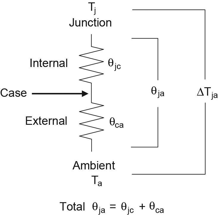
FIGURE 3. Total device thermal resistance includes internal and external resistance.
Picking a Heatsink
One way to cool a component is by moving air across its surface, keeping Tambient low. You can use a fan or even orient the component so that natural convection keeps air moving across the hot surface. This technique is limited to power dissipation of about one watt or less, particularly in small components that have small surfaces.
For larger amounts of heat, a heatsink is required to lower θca. Heatsinks can be anything sufficiently massive and thermally conductive to conduct heat away from the component. Almost any metal object can be used as a heatsink, including printed circuit board ground planes and the equipment chassis. You don’t have to use a manufactured heatsink!
Semiconductors that are intended to dissipate heat have packages designed for use with a heatsink. For example, in the TO-220 package, the semiconductor sits directly on a metal tab that is electrically connected to the device. The TO-3 package is completely metal and is also electrically connected to the device inside. Why electrically connected? To avoid an intervening layer of material that would increase thermal resistance. The aggravation of having a non-isolated package is well worth the improved heat transfer efficiency.
The heatsink’s thermal resistance in °C/W tells you how much the surface temperature (not the junction temperature) of the attached component will rise per watt of heat. Assume that this is a value based on a natural convection figure. Using a fan lowers the heatsink’s thermal resistance. High power heatsinks will have values of θca that are specified for different amounts of air flow.
To select a heatsink, start by specifying a maximum junction temperature. Calculate the amount of power the component will dissipate. Since θjc is fixed, calculate maximum case temperature:
Tcmax = Tjmax - P x θjc
Estimate the ambient temperature. The required thermal resistance of the heatsink is then:
θca = (Tcmax - Tambient) / P
From the catalogs or websites of heatsink manufacturers, you can now select a heatsink that has both the right θca and fits in your enclosure.
An Example of Heatsink Selection
A common heatsink application is dissipating heat from a pass transistor or voltage regulator, such as the common 7805. (Download the 7805 data sheet from www.datasheetarchive.com) Let’s say the 7805 will drop the input voltage from 12V to 5V at its output with a peak sustained current load of 0.5 amps. We’ll also assume that the inside of the electronics enclosure will be 33 °C or 10 °C higher than room temperature of 23 °C.
- Start by calculating total heat dissipation: PD = (VIN - VOUT) x I = 7V x 0.5 A = 3.5 W. Without a heatsink, this regulator will get mighty toasty!
- Look up the 7805 junction to case thermal resistance: Codi Electronics specifies it as Rj-c = 5 °C/W.
- If we set maximum junction temperature at 80 °C, then Tcmax = Tjmax - P x θjc = 80 - 3.5 x 5 = 62.5 °C.
- The heatsink’s thermal resistance must be no larger than θca = (Tcmax - Tambient) / P = (62.5 - 33) / 3.5 = 8.4 °C/W.
- Browsing the Digi-Key selection of heatsinks (www.digikey.com), I found that the IERC 7-340-2PP-BA is a nice choice, with a 7 °C/W rating. The margin of 1.4 °C/W also allows for a small additional amount of thermal resistance in the insulating pad required between the IC and heatsink.
You might decide that the heatsink is too big (it’s about a cubic inch) or too expensive (single quantities are $1.75). In that case, you must allow a higher junction temperature or figure out how to reduce the power dissipation in the regulator. You could also lower the ambient temperature. Any of these three will allow you to use a heatsink with a higher thermal resistance. If you’d like more information on heatsink selection, heatsink manufacturer Aavid-Thermalloy has published a short tutorial on picking heatsinks at www.aavidthermalloy.com/technical/papers/semisize.shtml
Summary
That’s the basic process: Figure your heat load, specify the maximum temperature, determine the thermal resistances involved, and go shopping! Eventually, you’ll become skilled at managing heat — both in reducing its generation and in getting rid of it. And you can chalk it all up to thermal analysis. NV