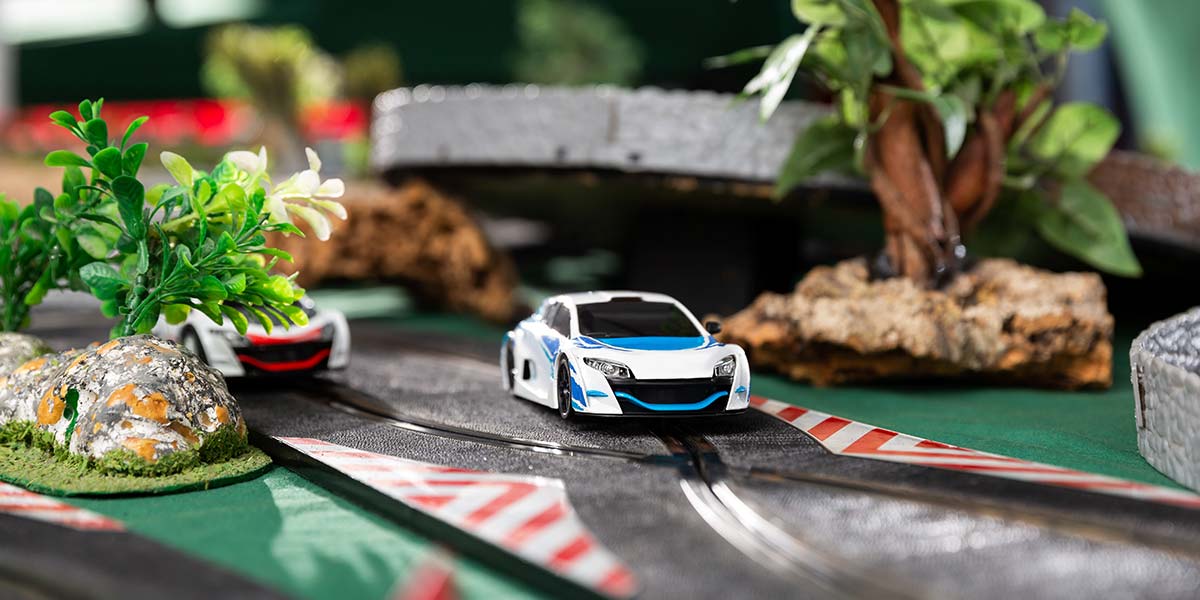
Many of us have fond memories of assembling sections of track and spending many enjoyable hours racing slot cars, either alone or with friends. Maybe it’s a hobby you’d like to get back to (or never left) or share it with the next generation of slot-car racers in your family. Racing these miniature cars around a track is only part of the fun!
Just like with model railroad enthusiasts, race car tracks can be assembled as a permanent layout where building scenery and accessories can be as much fun as the actual racing itself — and take the racing up a notch as well by putting the track in a setting that’s more realistic than the basement floor. It can be very much like building a diorama that has “live” components that can bring many hours of interactive enjoyment.
With a little amount of expertise in electronics, there are definitely many accessories we can build ourselves — probably enough to fill at least a small book. Since we don’t have that much space here, I’ll highlight only a few of these project ideas, in no particular order.
Common Requirements
All the circuits discussed here have a few things in common. Part of this is to make life a bit easier for the builder. The detector used in the track to detect the passing of a car in one circuit can be used in all of the other circuits as well, as long as the detector provides a +V signal (logic high or “1”) when a car is detected, and goes to ground (logic low or “0”) when no car is detected.
There is a large variety of detectors out there, from magnetic to light-sensing — far too many to analyze and discuss in one article. As long as it meets the previously stated criteria, is easy to work with, and the builder is comfortable using it, then it’s the right one for our circuits.
Other things these circuits have in common are:
- Standard parts — nothing exotic or expensive, so they’re easy to source.
- +12V operation — a common voltage available by easily-obtainable power supplies.
- No microprocessors — no one has to learn any computer languages or do any complex programming.
Lap Counter
BCD (binary coded decimal) counters — programmed to count upwards (and they start at zero when powered up) — are driven directly from the car sensor. It will count up to lapse 99 using seven-segment LED displays, or if a higher count is desired (like the “endure” or endurance race), another 14510 counter is wired into U2 the same way that U2 is wired into U1, along with adding another seven-segment LED driver (U4) and seven-segment LED (wiring information shown in the side-bar).
Switch SW1 resets the counters to zero; ready for the next race. The size of the seven-segment displays can be chosen to look most realistic for the scale of your race cars and mounted into your own custom-made score board (more on that later).
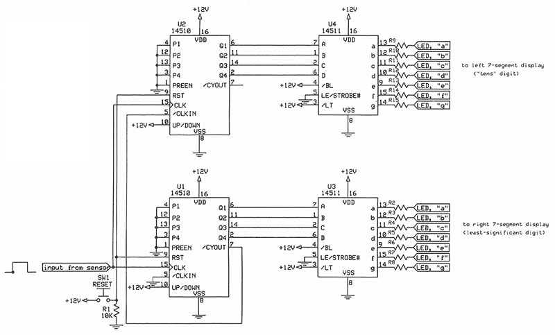
Lap Counter schematic.
Notes:
- Sensor type used not critical as long as logic high = +V and logic low = 0V.
- For LED resistor values, see text/Parts List.
- Duplicate circuit for each track.
| Designator |
Qty |
Value |
Description |
Comments |
| |
1 |
276-168B |
RadioShack blank PCB (or equivalent) |
|
| LED1, LED2 |
2 |
Display |
Seven-segment LED displays, user’s choice |
|
| R1 |
1 |
10 KΩ |
Resistor, 1/4W 5% |
|
| R2-R15 |
14 |
620Ω |
Resistors, 1/4W 5% |
Assumes 2V, 20 mA LED segments |
| Sensor |
1 |
|
Track sensors, user’s choice (see text) |
|
| Sockets, IC |
4 |
16-pin |
Sockets, IC, 16-pin solder-tail |
Sockets, IC, 16-pin solder-tail |
| Sockets, LED |
2 |
|
Socket |
Sockets, LED |
| SW1 |
1 |
|
Switch |
Switch, momentary, normally open |
| U1, U2 |
2 |
|
14510 |
BCD counters |
| U3, U4 |
2 |
|
14511 |
Seven-segment LED drivers |
Lap Counter Parts List.
And the Winner is ...
The circuit titled “Winner Detector” works as follows: On initial power-up, Q of both latches U1A and U1B are logic low (0) and the not-Q is a logic-high (1). When either of the two-input AND gates sees a logic 1 on both inputs — one from a latch, the other from the car sensor — it sends a logic 1 to the “SET” input of the other latch.
This will cause two things to happen. First, the not-Q output of the other latch goes to a logic 0, so that the corresponding LED cannot light. Secondly, the Q output of the triggered latch goes high causing the corresponding LED to light, indicating the winner. Appropriate LEDs can be mounted either at the finish line or on a scoreboard, along with other pertinent information.
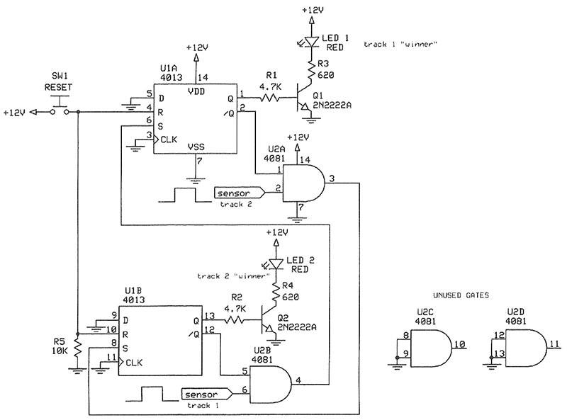
Winner Detector schematic.
Notes:
- Sensor types not critical as long as they provide +V on logic high and 0V on logic low.
- LED current-limit resistors based on +12V supply, 2V 20 mA LEDs.
| Designator |
Qty |
Value |
Description |
| |
1 |
276-168B |
RadioShack blank PCB (or equivalent) |
| SW1 |
1 |
Switch |
Switch, momentary, normally open (N.O.) |
| U1 |
1 |
4013 |
Dual J-K flip-flop/latch |
| Sensors |
2 |
|
Track sensors, user’s choice (see text) |
| U2 |
1 |
4081 |
IC, quad two-input AND gate |
| Sockets, IC |
2 |
14-pin |
Sockets, IC, 14-pin solder-tail |
| R1, R2 |
2 |
4.7 KΩ |
Resistors, 1/4W 5% |
| R3, R4 |
2 |
620Ω |
Resistors, 1/4W 5% |
| LED1, LED2 |
2 |
LED |
LEDs, 2V mA (color = user’s choice) |
| Q1, Q2 |
2 |
2N2222A |
Transistors, NPN, general-purpose switching |
| R5 |
1 |
10 KΩ |
Resistor, 1/4W 5% |
Winner Detector Parts List.
Countdown to Start
The circuit titled “Countdown to Start” operates as follows: On initial turn-on, the 4040 binary counter comes up with a zero count on the output, and U5-9 (dual J-K flip-flops, used here as latches) have a logic 0 on the Q output and a logic 1 at the not-Q output.
With the LEDs and their driver transistors lit because of the logic 1 on the not-Q latch output, we have 10 lit LEDs. Using standard LEDs (chassis-mount) mounted vertically on a “pole” near the car’s starting line, all will be lit.
When the circuit starts (switch SW1 is momentarily depressed to cause the Q output of U10A to go high, starting the 555 oscillator), the 4040 will start counting from 0-10. As each whole number (1, 2, 3, etc.) is reached, an LED will turn off starting with the LED labelled 1. If this LED is at the top of the pole (with LED 10 at the bottom), the race cars know to start when the last LED (#10) turns off. If the builder would like the reverse to happen — lights start in the “off” condition and light as time progresses — simply wire the LEDs and drivers to the “Q” output of the latches instead of the not-Q output.
The 555 timer — which provides the clock pulses driving the binary counter (4040) — is shown with RC values that will cause it to run at 1 Hz (one pulse per second).
The timer speed can be calculated with the formula T=1.44/(R23+2R24)C1; for a symmetrical waveform, the two resistors should be close to the same value.
If the timer’s output waveform becomes too asymmetrical, it may reach a point where it looks more like a voltage spike than a digital waveform, causing the binary counter to not count correctly
U4C and U4D as two-input AND gates (wired here as a three-input AND gate) provide a stop/reset pulse to the 4040 counter (U2) and the RESET input of U10A (another J-K flip-flop used as a latch), causing the Q output to go low and turning off the 555 oscillator.
The observant builder has probably noticed by now that the RESET of the 555 timer is toggled to +V to cause it to operate, while the 4040 is held at 0V to run, and pulled to +V to stop and reset the counter. No, this is not a mistake. These ICs really do have opposite logic levels required for their respective RESET functions!
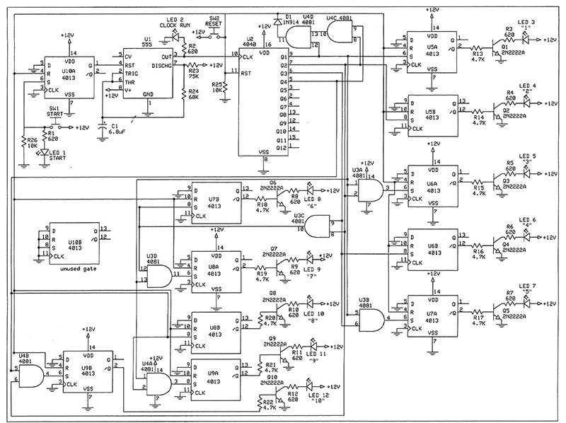
Countdown to Start schematic.
| Designator |
Qty |
Value |
Description |
| |
2 |
276-168B |
RadioShack blank PCB (or equivelant) |
| D1 |
1 |
1N914 |
Diode, general-purpose, switching |
| LED1-L12 |
12 |
LED |
LEDs, 2V 20 mA (color = user’s choice) |
| Q1-Q10 |
10 |
2N2222A |
Transistors, NPN, general-purpose, switching |
| R1-R12 |
12 |
620Ω |
Resistors, 1/4W 5% |
| R13-R22 |
10 |
4.7 KΩ |
Resistors, 1/4W 5% |
| R23 |
1 |
75 KΩ |
Resistor, 1/4W 5% |
| R24 |
1 |
68 KΩ |
Resistor, 1/4W 5% |
| R25, R6 |
2 |
10 KΩ |
Resistors, 1/4W 5% |
| Socket, IC |
1 |
Eight-pin |
Socket, IC, eight-pin solder-tail |
| Sockets, IC |
8 |
14-pin |
Sockets, IC, eight-pin solder-tail |
| Socket, IC |
1 |
16-pin |
Socket, IC, eight-pin solder-tail |
| SW1, SW2 |
2 |
Switch |
Momentary, normally open (N.O.) |
| U1 |
1 |
555 |
IC, oscillator |
| U2 |
1 |
4040 |
Binary counter |
| U3, U4 |
2 |
4081 |
Quad dual-input AND gates |
| U5-10 |
6 |
4013 |
Dual J-K flop-flops/latches |
Countdown to Start Parts List.
Assembling the Displays
Once built, the circuits can be mounted in whatever enclosure the builder chooses. Several different types are available from the same resources that electronic parts are available from. The wires can be routed under the table that the track is on to wherever the displays are mounted.
The displays can be mounted at the appropriate place in the diorama by making a homemade score board near the track. Supplies can be ordered from a company called Plastruct (further details are listed under Resources).
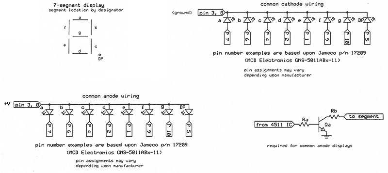
Miscellaneous LED data.
Conclusion
I’m certain there are many more gadgets that can be built for slot-car racing, but hopefully the ideas discussed here will provide a starting point that will either renew someone’s interests in this hobby or provide a way for someone who’s already active in the hobby to enhance their setup. NV
Resources
The following resources represent a short list of what’s available out there. I’ve used these businesses frequently during my building career with good success.
Electronic Parts
Jameco Electronics
www.jameco.com/webapp/wcs/stores/servlet/StoreCatalogDisplay?langId=-1&storeId=10001&catalogId=10001
Digi-Key Electronics
www.digikey.com
Mouser Electronics
www.mouser.com
Plastic Shapes, Model Building Supplies
Plastruct, Inc.
https://plastruct.com
In a limited way, several of the more common supplies made by Plastruct are also carried by many hobby and/or craft stores, so check your neighborhood stores too.
Downloads
What’s In The Zip?
Schematics
LED Data