What It is and How to Measure It
Backlash can have a detrimental effect on tool life and on your CNC router’s ability to maintain accurate positioning of the X, Y, and Z axes. In this article, we’ll look at the problem of backlash in CNC routers. Once you understand what role it plays, you’ll want to diminish its impact on your machine. Whether you own or intend to build/buy a CNC router, make it a habit to routinely check for backlash. It could save you some money and/or aggravation.
If you have a metal or wood bench vise in your workshop, you’ve probably experienced “backlash” and not even noticed the problem. For example, if you secure a piece of wood in a vise and then begin to loosen the jaws, you’ll notice that the vice handle will rotate somewhere between 10 to 90 degrees or more before you see any movement of the jaws.
In other words, the amount of “slop” or “play” in between the threads of the large lead screw and the threads within the vise jaws creates a backlash situation.
It’s important to note in our bench vise example that the delay in the movement (backlash) of the jaws happens in both directions — tightening or loosening of the vice.
On a vise, backlash is not too big of a problem, but on CNC routers, it can put a dent in your tool life and the accuracy of your X, Y, and Z axes.
Figure 1 shows a cutaway view of the Acme lead screw and nut setup on my desktop CNC router. Depending on which direction the stepper motor rotates, the nut and lead screw attached to the gantry support board will move the Y axis forward or backwards.
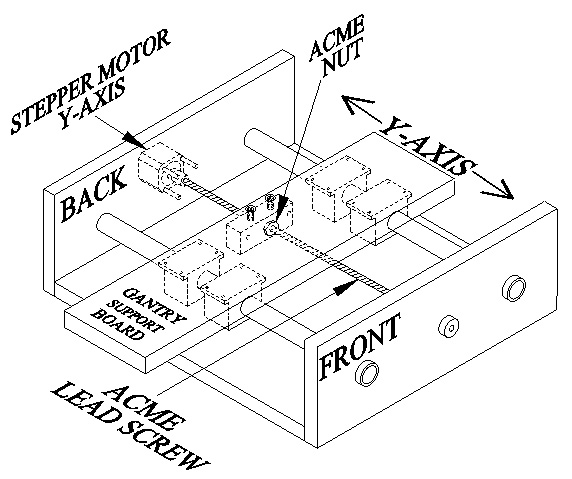
FIGURE 1.
A close-up view of the Acme lead screw and nut is shown in Figure 2 below. Notice in the top diagram how each Acme lead screw thread is engaged on the right side of each nut thread. Now, when the lead screw is rotating clockwise (CW), backlash is not a problem because both the lead screw and nut threads are fully engaged with each other (no gap). However, backlash is introduced into the system when the lead screw changes to a counterclockwise (CCW) rotation.
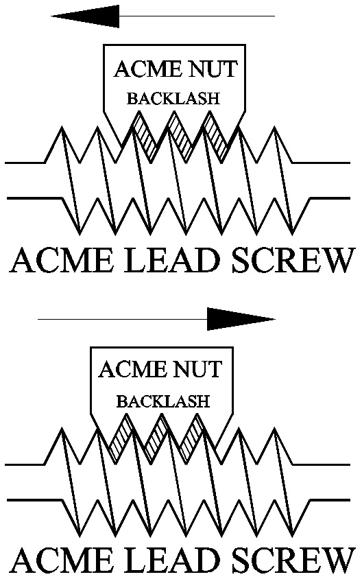
FIGURE 2.
Notice in the bottom diagram how the lead screw threads must traverse the gap between the nut threads before they become fully engaged again. The gap in between the forward and backward engagement of the lead screw and nut threads is called backlash. In other words, backlash (hatched area in Figure 2) can be seen in either direction as a direct result of rotational shifts made by the lead screw.
Even though we’re talking about thousandths of an inch here, it can be enough to cause a couple of problems. For example, look at the “Chip Load” chart in Figure 3.
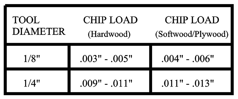
FIGURE 3.
The chart is recommending that for hardwood, a 1/8” diameter tool bit (cutting tool) should make wood chips no larger than .005” and no smaller than .003” in width. In other words, you should see wood chips (not sawdust) flying off your tool bit as it cuts into the workpiece.
Chip load size is important because wood chips remove heat from the tool bit. Having too small of a chip load builds up excess heat in the tool bit. Heat buildup shortens tool life. On the other hand, too big of a chip load can break a small diameter tool bit.
Backlash can change the recommended chip load size. During a “climb” cut scenario, the cutting tool edge (flute) tends to grab the workpiece. Consequently, the cutting tool will move a distance equal to the amount of backlash in the system.
As you can imagine, backlash also diminishes the accuracy of a CNC router. Accurate positioning of a tool bit is essential when locating the center of a hole, engraving an intricate pattern, or adhering to drawing tolerances.
BACKLASH: HOW TO MEASURE IT
Measuring backlash is not that hard to do — provided you have the right equipment. Figure 4 shows the “Dial Indicator” ($15) and holder ($23) I purchased from Amazon (see Parts List).
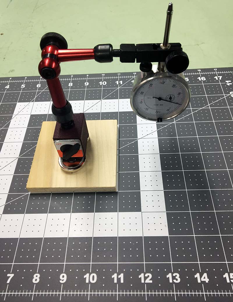
FIGURE 4.
The dial holder has a magnetic base. It’s normally used on a vertical CNC milling machine because it can attach itself to the machine’s metal framework.
Since the spoiler boards on CNC routers are normally made of wood, you have the option of finding a small steel plate somewhere and using it as a base for the dial holder. Or, you can construct my simple wood and neodymium magnet ($9; Amazon) contraption shown in Figures 5 and 6. Either way, just make sure the dial and holder don’t move while testing for backlash.
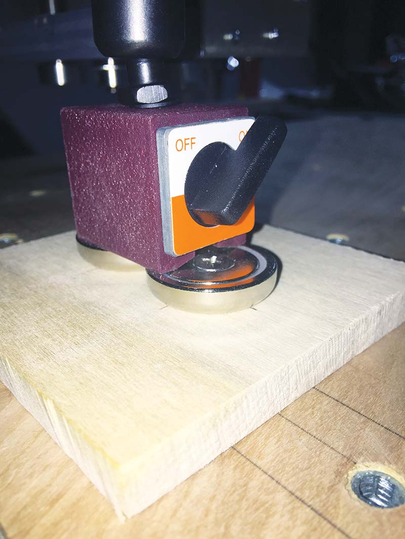
FIGURE 5.
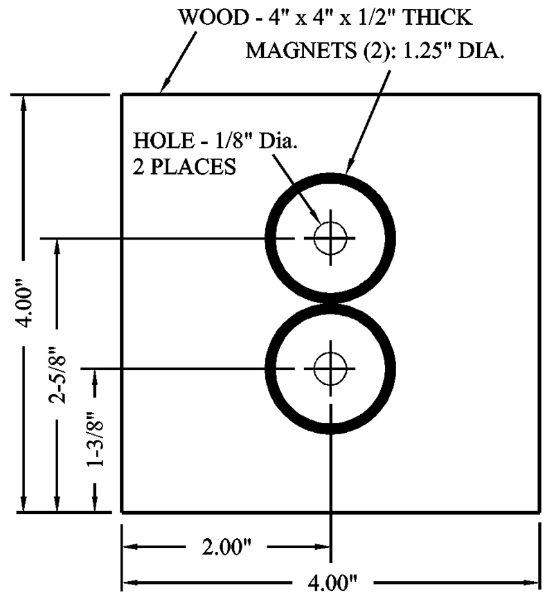
FIGURE 6.
(WARNING: The magnets used in this article are surprisingly strong. I got the tip of my finger caught between two of these neodymium magnets as they accidently snapped together. It caused a small blood blister to appear. Please, don’t let small children get a hold of these magnets.)
TIME TO TEST YOUR RIG
In preparation for the backlash test, you need to turn off any backlash compensation in your CNC control software. In Mach 3, for example, just go to the ‘Config’ menu and select ‘Backlash’ from the list. Before you clear (zero out) any default settings, take your phone and snap a photo of the current screen — just in case you want to return to the original settings after the test.
It’s also important to verify that your lead screw couplings on all three axes are tight. In other words, if the connectors between the stepper motors and lead screws are loose, the stepper motor shaft will slip inside the coupler. This can cause a delay in moving the X axis. Therefore, any slippage in the couplings must be addressed or unexpected errors will be introduced into the backlash test.
Okay, you’ve assembled all the required equipment you need to measure backlash. Now, let’s start with the X axis. Set up the dial indicator and holder as shown in Figure 7. Make sure the dial indicator plunger is perpendicular to the point of contact.
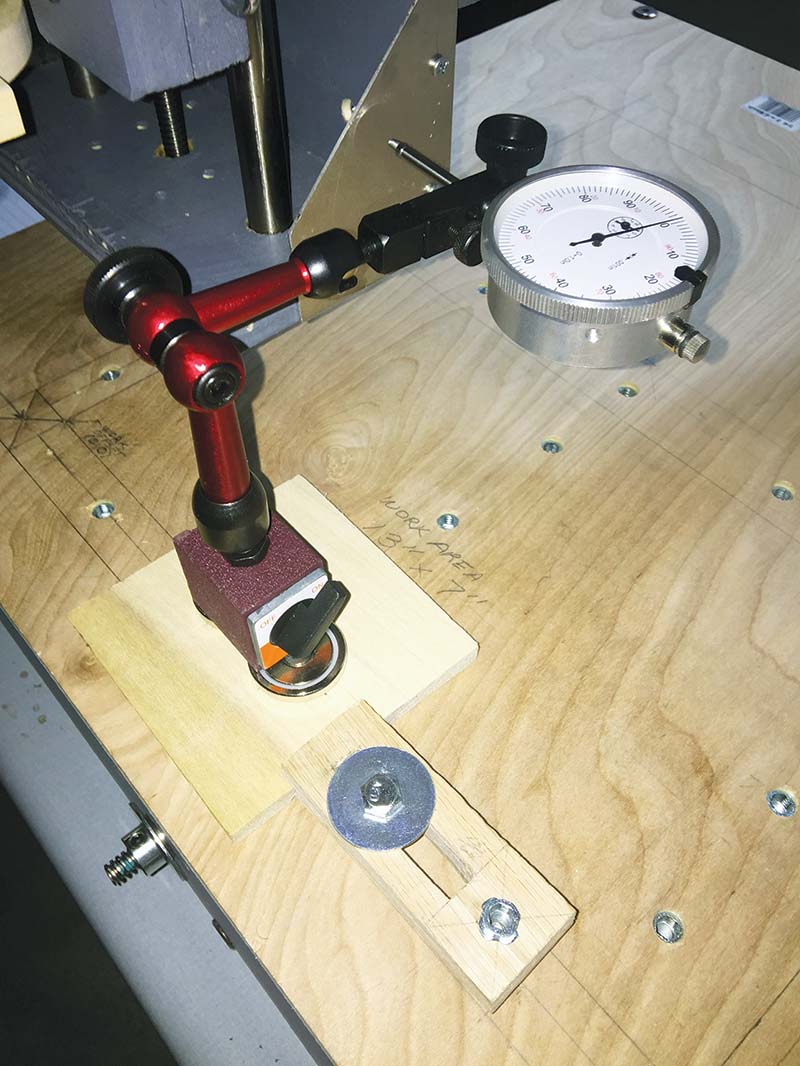
FIGURE 7.
Now, SLOWLY move (jog) the X axis towards the dial indicator until the dial indicator plunger is depressed about a quarter of an inch. This procedure is called preload. The preload insures that any backlash in the forward motion of the X axis is eliminated. Next, turn the outer rim of the dial indicator so the needle reads zero on the dial.
In Mach 3 or your particular CNC control program, set the ‘Jog Mode’ to ‘Step’ and equal to one thousandth of an inch (.001”). Now, move the X axis towards the dial indicator by tapping the X axis jog button 10 times. The X axis should move the dial indicator needle to the .010” mark. Note that each line (mark) on the dial is .001”.
Now, reverse the movement of the X axis by again tapping the jog button 10 times in steps of .001”. If the needle on the dial doesn’t land on the zero mark, you have some backlash in the amount the dial needle is away from the zero mark.
For example, if the dial indicator needle moved from zero to .010” in the forward direction on the X axis, then it should move from .010” to zero in the reverse direction. If you find when you reverse the movement on the X axis that the needle lands on the four thousandths mark on the dial, you have .004” of backlash on your X axis.
Now, repeat the above procedure a few times at different locations along the length of the X axis.
STEP AND REPEAT
Checking for backlash on the Y axis and Z axis on your router is just a matter of repeating the procedure we used on the X axis. Figure 8 shows how I checked for backlash on my Y axis.
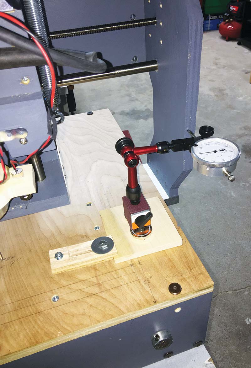
FIGURE 8.
Figure 9 shows the setup for my Z axis.
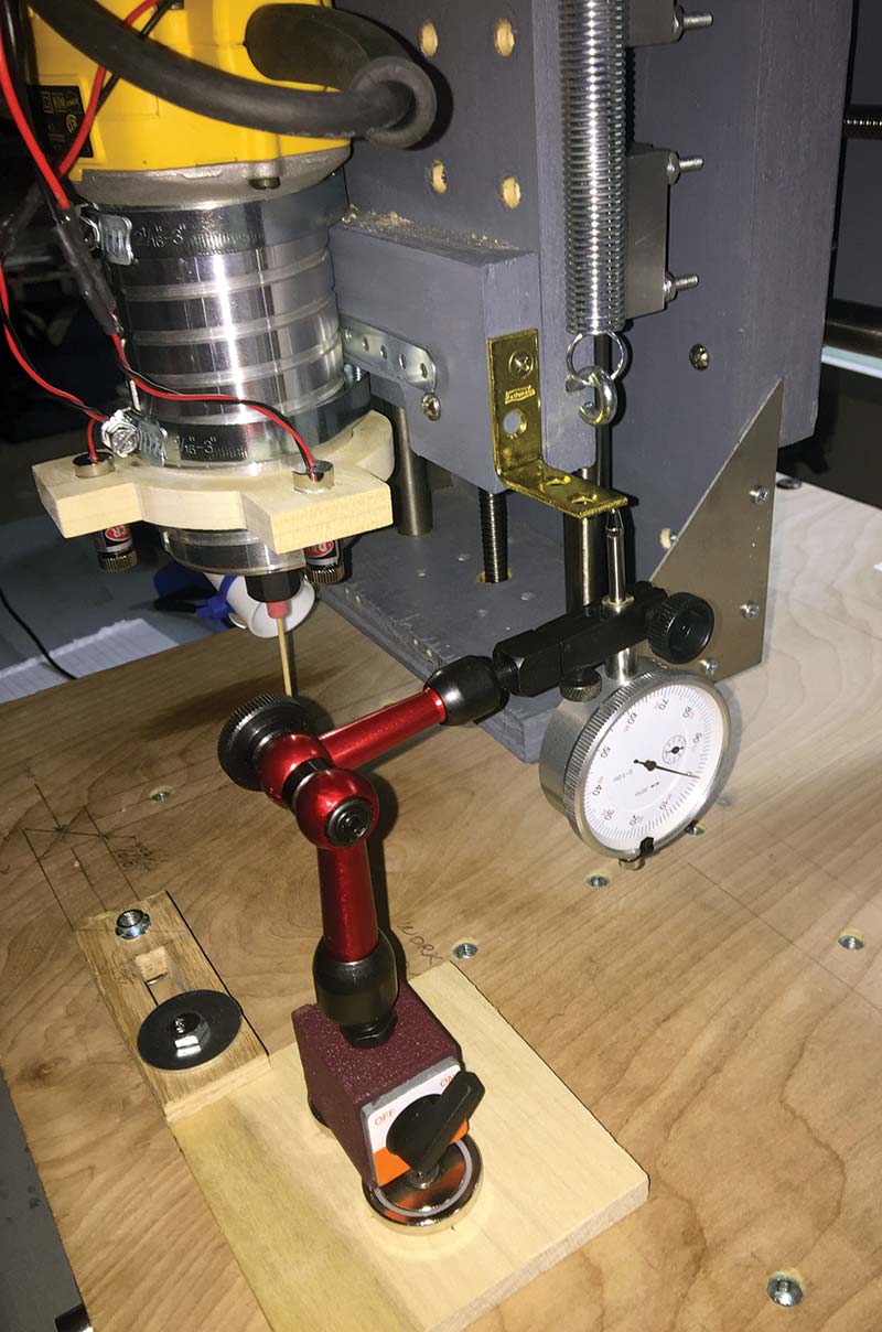
FIGURE 9.
After you test for backlash on the X, Y, and Z axes, calculate an average for each axis.
Now, enter the test results into the CNC motion controller’s backlash screen.
Finally, once the backlash problem is eliminated from your machine, run the setup procedure for “Steps per Unit” in Mach 3 (or in whatever CNC control software you’re using). This will insure the stepper motors are rotating the correct number of steps for a given unit of measurement.
In other words, when the digital readout (DRO) in your CNC control software displays 7.00” of X axis movement, your router will have moved exactly 7.00”.
COMBATING BACKLASH
There are two ways you can reduce the effects of backlash on a CNC router: software compensation or hardware compensation.
On the software side, you can manually adjust the amount of backlash compensation on the X, Y, and Z axes through your CNC control software. For example, go to the main screen in Mach 3, and select ‘Config’ from the menu. Then, select ‘Backlash’ from the list.
On the hardware side, backlash can be corrected by adding a spring loaded “anti-backlash nut” assembly to the lead screws on all three axes (see Figures 10, 11, and 12).
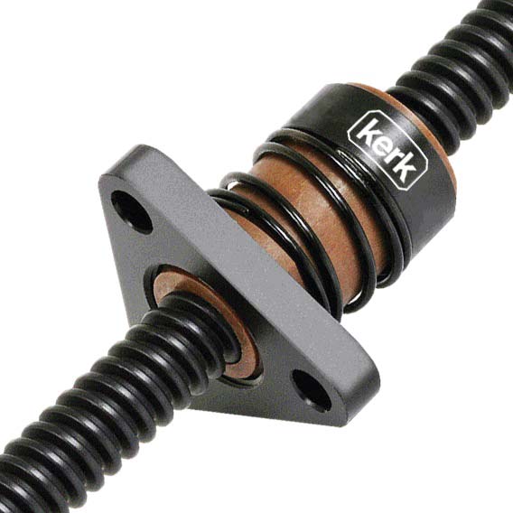
FIGURE 10.
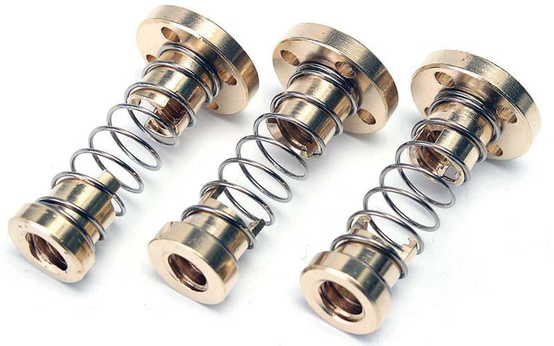
FIGURE 11.
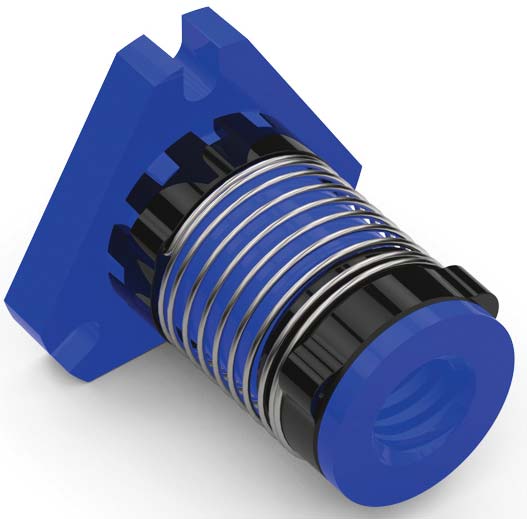
FIGURE 12.
Users who own or are building a rack-and-pinion type of CNC router can employ spring-loaded tensioners, anti-backlash split pinion gear, or a dual pinion drive to reduce backlash.
LAST WORD ON BACKLASH
It’s possible to achieve zero backlash on your X, Y, and Z axes either by installing some anti-backlash hardware and/or adjusting your CNC control software. Generally speaking, any backlash that is above .007” is better minimized with anti-backlash hardware rather than trying to adjust it within your CNC control software.
Typically, .001” or .002” of backlash per axis is an acceptable amount of play for a CNC router that cuts wood, plastic, and foam.
With that being said, you shouldn’t become obsessed with the goal of completely eliminating it from your CNC router. A certain amount of clearance (play) between the lead screw and nut is necessary in order to allow for thermal expansion/contraction, debris extraction, and lubrication.
Finally, since normal usage of any mechanical system produces wear and tear, it might be a good idea to routinely test your machine every 3-4 months just to verify the anti-backlash system is working as expected. Any minor backlash problem (few thousandths) you discover can be fixed within your CNC control software. NV
Parts List
| ITEM |
QTY |
DESCRIPTION |
PART# |
SOURCE |
APPRX COST |
| 1 |
1 |
Neodymium Round Base Magnets with Mounting Screws (pack of 4) |
HLMAG05 |
Amazon.com |
$9.99 |
| 2 |
1 |
Magnetic Base for Dial Indicator |
KAMB50F |
Amazon.com |
$25.99 |
| 3 |
1 |
Triton 1” Dial Indicator, .001” Graduation Travel |
ALL-52000 |
Amazon.com |
$15.23 |