Crystals That Make The World Go ‘Round
Strike a crystal goblet with a spoon, and you immediately have both the attention of your guests and the sympathetic resonance of other goblets on your sumptuous holiday table.
What is happening here? Well, you have created a crystal oscillator that generates acoustic waves in the air. It’s an impulse oscillator, wherein the peak movements of the glass and of the ensuing waves of air pressure decay exponentially over time. Your perceived “crispness” of this lovely chiming sound correlates with the actual mechanical “Q” of the singing glass: how sharply the resonant frequency peaks.
Now, common glass is an amorphous solid but arrange the silicon dioxide atoms in a particular rigid rectangular array and you produce a crystal capable of acoustic oscillation in an electronic circuit. And don’t stop there, obtain a diamond saw — by slicing the hexagonal crystal at an appropriate angle to its long axis, you can extract a thin slab whose natural acoustic resonance is significantly independent of temperature changes.
Then, grind your slab to a suitable radius and thickness, and you can accurately pre-determine its natural mechanical resonance. Deposit a thin foil of gold on either side of the resultant quartz disc (Figure 1), and bring each foil out on conductive leads.

FIGURE 1. A quartz crystal oscillator element.
Voilà! You are now in possession of an oscillator technology of formidable power for use in the everyday world of audio, radio, precision filters, television, radar, microwave communications, missiles, space probes, computers, power tools, calculators, cell phones, children’s toys, alarm systems, and digital watches. It is not surprising that this same everyday world demands several billion quartz crystals every year!
Quartz is a natural mineral, consisting of silicon dioxide in crystalline form. Today, quartz crystals are grown artificially — a vital process in a world of finite resources. Quartz is a piezoelectric material. This means that although it does not conduct electricity, voltages across it can produce internal mechanical strains in the crystal lattice, and these strains can reverse the effect, producing voltages. By applying an AC excitation voltage across the crystal at its natural acoustic resonance, the strains can be optimized and used in feedback to control the frequency of the exciting voltage itself, forcing a sustained, accurate, and stable frequency.
We are used to thinking of the crystal oscillator as solely an electronic device but, in reality, it contains an acoustic control element, vibrating at frequencies usually well above that of human hearing. Piezoelectric oscillators are not just limited to quartz elements, since many ceramics work well also, and these are referred to as ceramic resonators. Physical packages range from those the size of a cigarette lighter down to TO-5 cans, .3” DIP packages, and recently, to surface-mount sizes and pin-outs.
Quartz crystals span an impressive frequency range from 10 kHz to 10 MHz. By designing the associated feedback circuit with a driving resonance close to one of the crystal’s upper odd harmonics, so-called “over mode” crystals can also be constructed to achieve frequencies up to 100 MHz, and above. In such a high volume industry, you would rightly expect a broad selection to be available, and so it is. To enumerate only a few of the common units: units for timing at 32.768 kHz (note that 32768/215 = 1 Hz); for intermediate frequency generation, such as 455 kHz and 10 MHz; 3.579545 MHz crystals for television color burst oscillators, and 14.31818 MHz for video displays; and a wide range of utility frequencies of quartz and ceramic resonators at multiples of 1, 2, 4, 5, 6, 8, 10, and 16 in the kHz, 100 kHz, and MHz ranges.
As we have seen previously in Part 1 and Part 2 of this series, RC relaxation oscillators implemented with IC timers can achieve temperature stabilities of .1%/C and unit-to-unit accuracies from 5% to 12%, depending on the RC components used. We did not discuss LC oscillators: They provide intermediate stabilities between RC and crystal designs. Their stability is suitable for much analog television and radio tuning where low cost is a primary requirement.
However, ultimate frequency stability (ignoring atomic clocks!) is reserved for crystal oscillators. An appropriately cut and excited quartz crystal can achieve remarkable frequency stability as its temperature varies and as it ages over time — and it can achieve frequencies much higher than those of RC oscillators. Stabilities of (±) 50 ppm/C are easily obtained and unit accuracy within 50 ppm is common. Aging stability of 1 ppm/day is not difficult to achieve. Be wary of specifications that do not separate out these stabilities, but just state some ambiguous “frequency stability” figure. Also avoid crystal oscillator salesmen in green blazers and white suede shoes.
In this final part of the series on timers and oscillators, let’s look at the fundamentals of crystal oscillators, phase locked loops (PLLs), and a few of their correlative design methods.
Crystallizing Your Understanding
We recall that RC relaxation oscillators alternately store and then “relax” electrical energy in the form of electrical charge on a capacitor. While a crystal oscillator is not commonly thought of (or referred to) as a relaxation oscillator, in essence its functioning differs only in the way it stores energy.
Take another look at Figure 1. The electrical energy of the applied AC voltage produces a periodic electrical field in the crystal that distorts it alternately in either direction, doing work on it in the form of stored elastic energy in the crystal lattice. Since reactive elements are, by definition, those that store and then return circuit energy, we should not be surprised to see that the equivalent circuit for a quartz crystal contains both an inductive element, as well as two capacitive ones.
Interestingly, this inductive response is achieved without the direct effect of a strong magnetic field — it occurs by virtue of the phase at which energy is stored and returned relative to the exciting voltage. As shown in the equivalent circuit, we can visualize the crystal as a large inductance of several henries (H), that is accessible to us only through a very small capacitance (Cs), typically less than a picofarad. Rs is only a few kilohms. At its resonant frequency, the crystal provides both positive feedback and loop gain suitable to sustain oscillation.
The “series” resonant frequency of the crystal is the resonance of the LCR branch of the equivalent circuit. The current in this branch reaches a maximum at resonance, and the formula for this is:
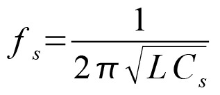
The parallel capacity, Cp, is the series combination of Cs in the inductive branch and the capacity of the mounting base, and Cp also has a resonant frequency. Quartz crystals are constructed to have their series and parallel resonances close together, within about 1%. This provides the versatility to work the device with a rapid phase shift near these resonances. Voltage-sensitive capacitors called “varactors” can be attached to “pull” the resonant frequency to provide tuning over a narrow range to realize voltage-controlled crystal oscillators (VCXOs).
As shown in Figure 1, the equivalent circuit for the crystal can be reduced to a series resistance Re, called the “effective resistance,” in series with a lumped reactance, Xe. It is in Re that the crystal dissipates its power as heat, and it is important not to overdrive the crystal since this stresses it and invites both a shift in frequency and outright failure. As we will see, an external resistor can be placed in series with the crystal to limit the drive level. Analogously, if you strike your crystal goblet too hard, it will shatter.
A Simple Quartz Oscillator
Let’s look at a simple quartz oscillator (Figure 2).
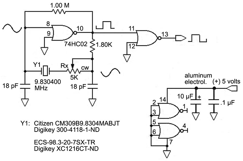
FIGURE 2. A simple quartz crystal oscillator.
This is an easy circuit to build and I recommend it as a starting point for understanding what happens. There are three main issues in crystal oscillator design: providing acceptable feedback to the crystal; not overdriving the crystal; and a relentless attention to grounding, shielding, and decoupling.
I have chosen a crystal with a high resonant frequency driven by a single 74HC02D NOR gate to provide loop gain and sustain oscillation. This circuit form is best used above 500 kHz when employing a 74HC series gate as the driving element. If you need frequencies lower than this, I recommend that you choose a higher frequency crystal and then divide it down with a suitable counter, such as the 74HC4020. (An exception to this resides with the 32.768 kHz clock crystal, where good circuit forms are shown by the manufacturers.) This maintains the high minimum slew rate specified for the 74HC logic family, of about 10 volts/microsecond when the input voltage on pin 8 is transiting through the linear region at 2.5 volts. For a sinusoid, the maximum slew rate is easily calculated:
Slew rate = 2pf V = 6.28 x 9.83x106 x (5.0/2) = 1.55 x 10⁸ volts/second = 155 volts/microsecond, where V is the amplitude of oscillation and = Vcc/2.
Work your oscillator circuit over a ground plane at digital ground, and keep the supply rail wiring short and decoupled closely at the oscillator.
Using an oscilloscope to obtain a snapshot of the phase relationships does much to understand the circuit without a detailed mathematical analysis. Use a high bandwidth oscilloscope probe. Adjust the compensation of your scope probe for a flat response, keeping the probe’s ground wire short and attached straight to the ground plane. Use a 10:1 probe with at least 10 megohms input impedance. Never probe the crystal driving circuit directly, except for analysis — sample at the buffer output. Trigger your scope on pin 8, the input to the NOR gate, and move around the loop to pin 10 of the NOR, and then to the right end of Y1. Note the accumulating phase lag. A phase lag of 180 degrees occurs twice around the loop, producing the required 360 degrees phase shift for oscillation: once across the NOR inverter and once across the crystal.
Using a digital frequency meter, adjust Rx to the largest value that will produce a small rise in output frequency when VCC is increased by a volt or so. If the frequency falls, or the circuit shows instability when VCC is increased, you are overdriving the crystal. Since power dissipation and frequency stability of the crystal are important, you will want to test your oscillator above the highest temperature at which it will be used, as well as observe its stability as it ages.
Should You Attempt to Design Your Own Crystal Oscillator?
If you are not designing for volume production — where cost will be primary — I recommend that you simply purchase one of the many integrated crystal modules offered in distributor parts catalogs and pay close attention to the manufacturer’s grounding and decoupling instructions. Otherwise, unless you are hewing close to established circuit forms in a conventional frequency range, you should consider one of the many integrated circuit drivers designed just for this purpose. Often, these cost only a few dollars more than the crystal itself.
Crystals have a variety of weaker oscillatory modes besides their main resonance. These are often referred to as “spurious” modes, which (before the 1970s) was a catch-all term for what they sometimes did, before modern analysis showed that these modes were actually chaotic responses with a logic all their own and not easily controlled by mortals. And one of these modes is to resist oscillation altogether! By contrast, a variety of integrated circuit drivers are offered for your frequency of interest, and these have the strong virtue that they are pretty much guaranteed to drive a particular crystal to oscillate at its primary resonance. Take a look at Figure 3.
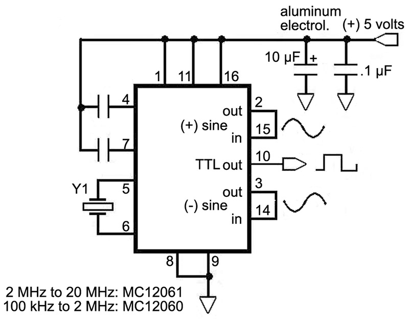
FIGURE 3. An integrated crystal oscillator driver.
Here we are using the popular MC1206X chip to support a crystal. This part has been discontinued by Motorola, but is readily available on-line from houses specializing in discontinued stock. I like it because the feedback loop is closed internally by a carefully designed driving amplifier with appropriate input capacity, impedance, and amplitude limiting for working with a quartz crystal. This avoids overdriving the crystal, promotes good frequency stability, and significantly simplifies your design task.
The PLL: Oscillators Enter a New Phase
Time was, for every really stable oscillator frequency required in a design, a circuit designer constructed a separate crystal oscillator, or at best, contrived to switch one of a set of quartz crystals into an accommodating positive feedback circuit. The 1950s and 1960s were the heyday of amateur radio and there was a large market for cut crystals in the authorized amateur frequency bands, as well as in commercial and military ranges. Both myself and one of the technical editors of this magazine “cut their electronic teeth” on ham radio during this era.
With the advent of the phase-locked loop (PLL) in integrated circuit form, frequency synthesis and synchronization took a great leap forward. Designers were able to free themselves from the tyranny of multiple crystals in order to realize a range of frequencies in a single instrument or communications device. Additional applications for PLLs include AM/FM detection, accurate motor control, and noise generation.
As we see in Figure 4, a PLL uses feedback to hold the output of an otherwise wandering voltage-controlled oscillator (VCO) in phase with a reference oscillator. Since the PLL can lock the phase of a wide range of variant sine wave oscillator frequencies in step with a single reference, a broad spectrum of stabilized frequencies can be produced as an output. And this stability rivals that of the reference oscillator itself.
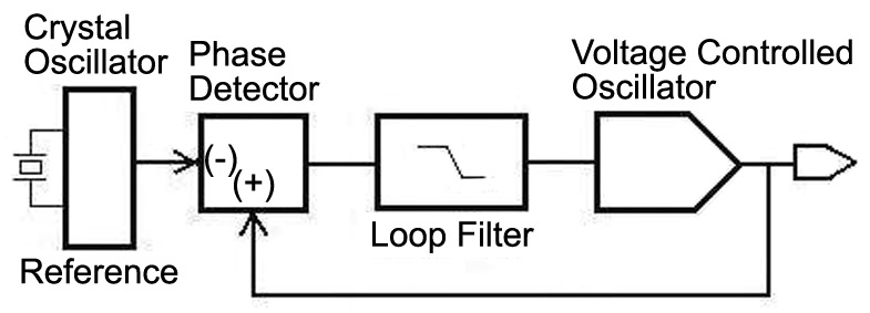
FIGURE 4. A block diagram of a Phase-Locked Loop (PLL).
Motorola offers an integrated circuit phase-locked loop in the form of the high speed CMOS MC74HC4046A1. Looking at this part’s datasheet can be intimidating. Designing with PLLs in production circuits is reserved to those with the courage of the thoroughly uninformed. But you can have a lot of fun playing with them!
Stability and response of the PLL feedback loop are major challenges; I recommend Reference 2 (below) as a guide, where more acute minds provide a detailed analysis. Computing the response of a PLL involves some rather advanced mathematics and should be confirmed by measurements. As in amplifier and filter design, the transient response of the PLL (to a sudden change in VCO frequency) will tell you quite a bit about stability, and as previously discussed in this series, there is simply no substitute for comprehensive and careful testing.
Conclusion
Learning to ride a bicycle or to swim ultimately involves jumping on, or in. Since crystal oscillator design is a non-fatal exercise, you should throw yourself in the pool and have fun. Unless you are an analog gunslinger, stay close to actual circuit designs given in the particular crystal manufacturer’s datasheets when you attempt “cut and fit” departures for your own designs.
Alternatively, if you want to design crystal oscillators for production rather than as a hobby, you should embrace established circuit forms, master the appropriate mathematics, and test your designs all the way to failure. A comprehensive discussion of crystal and ceramic oscillators would require many more pages than contained in this fine periodical. In any case, I hope I’ve pointed out the descriptive essentials, the caveats, and some of the potholes along your oscillator journey. NV
References
(1) High-Speed CMOS Data. Motorola, DL129/D, Rev 6. May 1996.
(2) Radio Frequency Electronics. Jon B. Hagen, Ph.D. Chapter 14, pages 128–140. Cambridge University Press, 1996. ISBN 0-521-55356-3. Dr. Hagen is the Director of the National Astronomy and Ionosphere Center at Cornell University.