Playing Around with Wireless Stuff
I’m a sucker for cheap electronic parts — especially wireless stuff. Just recently, a catalog from one of my favorite parts distributors (AllElectronics.com) came in the mail and was promoting some wireless modules: a transmitter (TX) and a receiver (RX) for just a few bucks each. I ordered immediately. What I got is shown in Figure 1. Now that I had these wireless modules, I wasn’t sure what to do with them. I had no plan or goal in mind. So, I decided I would just experiment for fun. This article sums up what I did and what I learned.
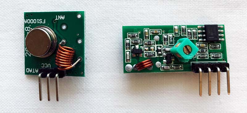
FIGURE 1. The cheap wireless modules discussed here. The transmitter is on the left and receiver on the right.
First, Do the Research
Of course, there was no documentation. So, as most of you do, I did an Internet search. I found some articles and other useful stuff. What surprised me was how many other vendors are selling these same modules cheaply. Some company must have dumped a boatload of these modules on the DIY marketplace. Our gain.
Transmitter Specifications
The TX module is the small one in Figure 1. The circuit is a single transistor oscillator and a transistor switch to apply the data input. Figure 2 shows a simplified diagram of the TX. The oscillator’s frequency is set by a surface acoustic wave (SAW) device.
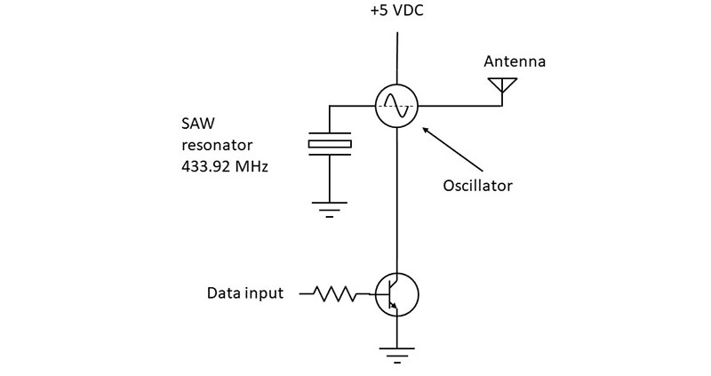
FIGURE 2. A simplified hypothetical representation of the transmitter (TX).
SAW devices are used mainly as filters, but also as a substitute for a quartz crystal. The SAW resonator in this TX sets the operating frequency at 433.92 MHz. This is one of the license-free industrial-scientific-medical (ISM) frequencies set aside by the FCC for low power short-range applications.
This TX is used to transmit digital data. It takes a serial digital bit stream that modulates the oscillator with on-off keying (OOK) or amplitude shift keying (ASK). What that amounts to is just turning the oscillator off and on with the switch transistor.
The TX puts out a binary 1 signal that is a burst of a 433.92 MHz sine wave equal to one bit of time of the data stream. A binary 0 is sent as no sine wave out. This TX can take data as fast as 8 kb/s. The output power is estimated to be about 10 mW or +10 dBm with a five volt supply.
Physically, the TX is very small: 19 x 19 mm square. It has four connector pins that will plug easily into a breadboarding socket. Power is a DC voltage in the three to 12 volt range with five volts recommended. The pin connections are shown in Figure 3.
FIGURE 3. The TX pin connections.
The limited documentation that I discovered pointed out that the TX could transmit without an antenna. Maximum range is three meters or so. Not very useful. Add a simple vertical antenna and the range jumps to 30 meters under the best conditions. You can make an antenna from 6.5 inches of solid copper wire oriented vertically.
Receiver Specifications
The RX is the larger of the modules in Figure 1. I didn’t find much data on this module other than it seems to exist in several different versions. It has dimensions of 30 x 14 mm and comes with a four-pin connector. My receiver module was labeled MX-RM-5V.
Figure 4 shows the pin connections. This illustration also shows an external transistor switch to operate an LED for test purposes. The RX operates from 3 to 12 VDC. The only details on the receiver are that its frequency of reception is 433.92 MHz and it demodulates OOK/ASK data. Sensitivity is said to be in the -105 to -115 dBm range. Not bad for a cheap receiver.
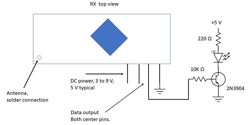
FIGURE 4. The RX pin connections showing the external transistor to operate an LED.
The data rate can be up to about 10 kb/s. Theoretically, the RX and TX match to form a complete transceiver. Testing will tell.
Testing the TX and RX
The ultimate test is to transmit some data and see if the receiver can recover it. Then, test the maximum range. For this test, I used two breadboarding sockets; one for each module. I used a 9V battery for both devices.
The TX supply voltage needs to be dropped to five volts. I used an available 7805 regulator to do this. The TO-220 package version is overkill for this project, but it was handy. The TO-92 package version would work just fine.
The RX also gets a five volt supply. I built a 555 timer IC oscillator data source for the transmitter; refer to Figure 5.
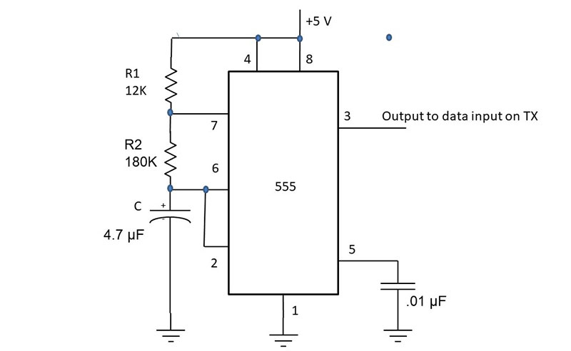
FIGURE 5. The popular 555 timer IC generates a rectangular bit stream used for testing.
It sends out a rectangular wave with a frequency of 1 Hz or so. It generates a continuous stream of alternating binary 1s and 0s to be transmitted.
For the receiver, I connected a transistor switch to flash an LED as the data is received and recovered. Figure 4 shows the details. I used another vertical 6.5 inch solid copper wire as the antenna that is soldered to the RX PCB (printed circuit board). This process is a challenge because the copper on the RX board is so small.
Use the minimum heat and solder as possible to avoid damage to the PCB and other parts. The TX has the same problem; the area to solder an antenna is tiny so requires careful soldering.
Some of the most critical components in this project are the antennas. Just find some wire that is stiff enough to stand up straight and that will also plug into your breadboarding socket. This wire forms a quick and easy quarter wave ground plane antenna.
I put the TX and RX on the bench in front of me. When I applied power to both, the LED did start to flash. So, the devices were communicating. However, if I turned off the TX, I still noticed some flickering of the RX LED output.
Looking at the data output pin with an oscilloscope showed a jumpy random set of output pulses. This is noise picked up by the receiver. Reducing the supply voltage on the receiver helps to reduce the noise. A supply voltage of less than about four volts reduces the data output pulse voltage. However, it may not be useful in operating something other than a flashing LED.
Next, I took the two units out in the back yard and set the TX on a table. I then held the RX and started walking away. I have a huge yard and I got about 30 feet away before the LED stopped flashing. Not a bad range for such small low power devices.
Range really varies with the terrain. Signals in this frequency range take a line-of-sight (LOS) path from TX to RX. Trees block signals and signals do not penetrate buildings very well. Open free space is what these simple wireless modules require for best performance.
A couple ways to extend the range is to boost the transmitter power from the 10 mW with a 5V supply to about 16 to 18 mW with 9V. Extending the antenna length — especially at the RX — should show some improvement. Playing around with the antenna position and orientation will also help.
Slowing the data rate down to 1 kb/s or less helps reduce transmission errors and that usually translates to longer reliable range.
What If It Does Not Work?
The most likely problem is a wiring error. I made several myself getting cross-eyed as I tried to wire up devices with 0.1 inch spacing between pins. Always double-check any wiring. Also, maybe one of the modules is bad. If you bought multiple modules like I did, you can swap out a suspected bad module for another one. My initial test didn’t work as the RX was not working. Replacing the RX module solved the problem.
Wireless Theory
There is a way to predict the maximum range of a single link between a transmitter and receiver. First, you can use the mathematical expression for free space path loss:
dB path loss = 37 + 20 log f + 20 log d
The frequency f is in MHz and the distance d between the transmitter and receiver is in miles.
An important take-away is that free space path loss increases with frequency. The higher the operating frequency, the higher the path loss. Higher frequency signals just travel less distance for a given power level.
One thing we need to do is convert our distance estimate from feet to miles. Let’s see what the path loss is for 30 feet. Since one mile is 5,280 feet, then 30 feet would be 30/5280 = 0.00568 mile.
dB loss = 37 + 20 log f + 20 log d = 37 + 20 log (433.92) + 20 log (.00568)
dB loss = 37 + 20 log f + 20 log d = 37 + 52.75 - 44.9 = 44.85 dB
Next, you should determine the power that reaches the receiver. A good estimate is given by:
Pr = Pt + Gt + Gr - Path Loss
Pr is the received power in dbm; Gt and Gr are the transmit and receive antenna gains. If simple quarter wave antennas are used, their gain is one. Assume a transmit power of 10 mW or 10 dBm. So, the received power is:
Pr = Pt + Gt + Gr - Path Loss = 10 + 1 + 1 – 44.8 dB = -32.8 dBm
The receiver sensitivity needs to be better than this for a communications link to be established. Using the receiver sensitivity of -105 dBm, you should see that -34.8 dBm is a higher power than -105 dBm; the receiver should easily pick up the signal with some gain to spare.
For a given receiver sensitivity that cannot be changed, the easiest way to extend the range is to increase the transmitter power if possible. Boosting the TX power by increasing the supply voltage from 5V to 9V should extend the range a bit more.
This calculation is only an approximation unless you really know the transmit power, receiver sensitivity, and antenna gains. There is also the issue of fade margin. This is an additional loss due to reflections from the ground or other objects that create multipath signals that produce multiple constructive and destructive waves.
Add a fade margin of 5 to 20 dB to the total path loss for longer range links. For such short ranges as used here, it’s not that relevant and can be ignored. Nevertheless, the calculation is a good starting point to determine the range of your equipment.
Applications
Most wireless transceivers are tied to a microcontroller that provides the data to the TX and accepts the data from the RX. That micro also runs an app, whatever that may be.
A few things come to mind as far as uses: a digital thermometer; a gate or door opening warning; and a light monitor. Garage door openers use wireless devices like this, but operate on 315 MHz. I suspect you could think up something to do with this. A useful variation is to have a TX and RX at each end of a wireless path for true two-way communications.
A missing part of the transceiver is having some kind of coding and formatting of data available. You could cobble together something like this with a big batch of TTL or CMOS gates, counters, and registers. You can also buy some IC encoders and decoders that will take care of that. These could be the Holtek HT12E encoder for use at the TX and the HT12D decoder to use at the RX. These parts are available from Jameco Electronics (www.jameco.com).
The HT12E encoder lets you deliver a simple data protocol consisting of a frame made up of an address and data bits. The encoder shown in Figure 6 accepts eight bits of address from DIP switches or some other parallel data source. The eight-bit address lets you accept data input from up to 28 = 256 sources. The chip adds four bits of data from switches or another digital source. An on-chip clock shifts the address and data out along with a header that the receiving chip will recognize and sync to.
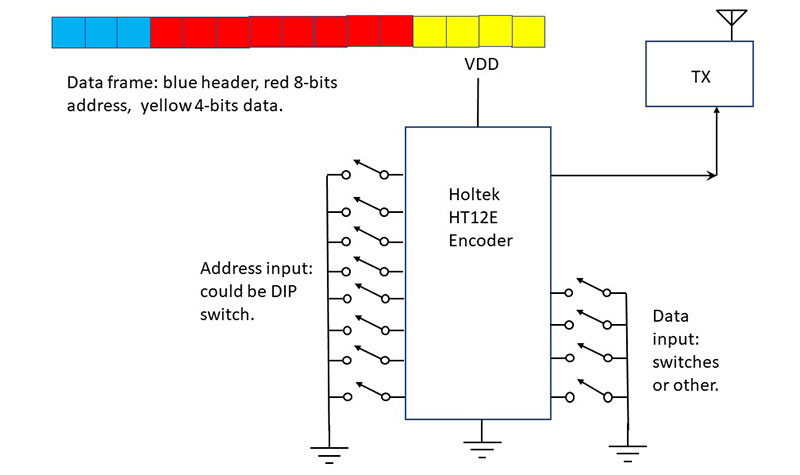
FIGURE 6. The Holtek HT12E CMOS encoder chip that delivers address and data to the transmitter. The transmitted frame is also shown: three bits of header; eight bits address; and four bits of data.
The HT12D is a decoder used at the receiver to identify the device or multiple devices from the data bits; refer to Figure 7. This chip accepts the serial data from the receiver, then processes it. It compares the received address against its own eight-bit address input so that it routes the accompanying data to the four data output lines. It will output the data or interpret it and provide an output. You can avoid using and programming a microcontroller in some applications by using these CMOS ICs.
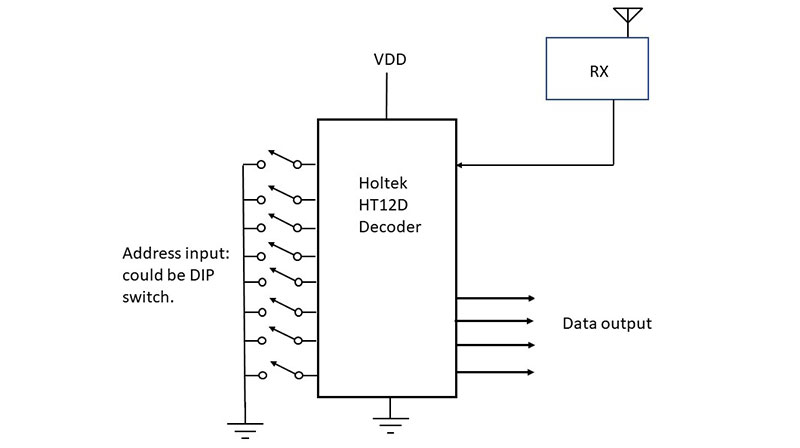
FIGURE 7. The Holtek HT12D CMOS decoder chip showing DIP switches to provide an address input that is used to compare to the received address that identifies the data to be sent to the output.
If you’re already a micro user and programmer, the TX and RX are easily interfaced to a microcontroller like the Arduino. Then, you can program the whole unit to implement the application you choose.
Making It Useful
Blinking an LED 30 feet away is not very useful. Granted this is not a high-tech solution, but with a few modifications, this TX-RX pair can be of value. It’s a good tool for turning remote electronic/electric loads off and on at some distance. Figure 8 shows one possible solution.
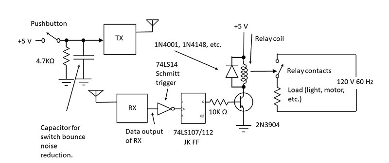
FIGURE 8. The wireless circuit for turning a remote external load off and on.
A transistor is used to operate a 5V relay. The diode across the relay coil protects the transistor when it switches off. The relay contacts are connected to an external power source such as the 120 VAC line. When the relay is activated, the contacts close applying power to the load — a light or pump or something else. Any external voltage source and load can be operated this way so long as the relay contacts are rated high enough.
Take another look at Figure 8. When the pushbutton at the TX is pushed, a burst of 433 MHz RF goes out. The receiver picks up the signal and demodulates it into a pulse that will change the state of the flip flop (FF).
The pulse out of the receiver is rounded and noisy, so it’s cleaned and squared up by applying it to a Schmitt trigger IC (TTL 74LS14 or CMOS CD4069).
Each time a pulse occurs, the FF will change state. The FF (TTL 74LS107 or 74LS112 or CMOS CD4027) will remain in one state until power is removed. Pressing the TX button again will change the FF state. Press the button to turn the load on; press the button again to turn the load off.
If the switch contacts bounce, you’ll get multiple pulses that will toggle the FF several times. You can minimize this problem by putting a capacitor across the 4.7K resistor in Figure 8. Experiment with several sizes to see what works. Values in the range from 0.1 µF to 10 µF should work.
What Else?
There are lots of other wireless modules available out there for short-range applications. They may be OOK/ASK devices that are designed for sub-1 GHz frequencies. Or, they may use FSK or spread spectrum modulation that are used in some of the well-known technologies like Bluetooth, ZigBee, or Z-Wave that work at 2.4 GHz.
I’ve used some of the Radiometrix TX1 and RX1 FM modules distributed by Lemos (www.lemosint.com) with good success on a couple of wireless projects. If you’re still just learning wireless, simple modules like the ones used here are best for learning. Give them a try.
If you have never experimented with wireless before, these modules are an inexpensive way to try it out. Wireless has been with us for over 120 years and is widely used. However, you’ll discover its real magic working with it at this level. NV