
As an engineer and avid electronics hobbyist, I wanted to build a device that would allow me to wirelessly turn my lights on and off without getting off my couch after a long day at the office. Plus, at the time, my wife was pregnant, and a device like this would make her life much easier. Initially, I only intended on building an electromagnetic wireless switching mechanism that worked in conjunction with an Android application. However, I ended up adding voice control and real time button state synchronization in the application as well.
How Does the Wireless Switching Work?
The switch was the first component in this build and the concept that fascinates me the most. I originally used an Arduino Uno and Ethernet shield, but the build was way too bulky and a complete eyesore (Figure 1).
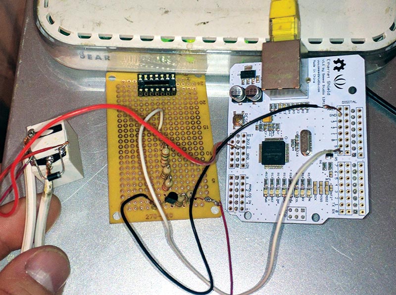
FIGURE 1. The original switch design.
Now, the switch is comprised of a small signal bipolar junction transistor, a single-pole/single-throw (SPST) normally-open five volt relay, and a Wi-Fi breakout board made by Adafruit (Figure 2).
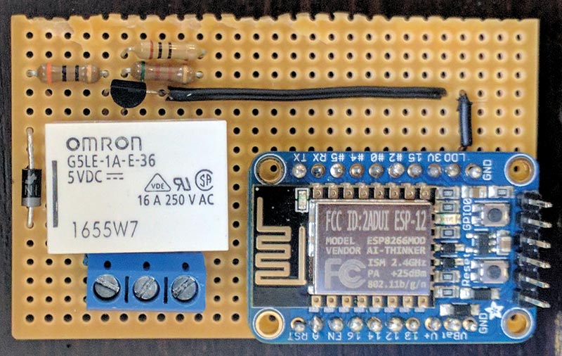
FIGURE 2. The new switch design.
The switch — more specifically, the relay — is inserted in between one of the wires on the extension cord. The switch then connects the broken wire on the extension cord when the relay coil is powered and then magnetized. Take a closer look at the switch in Figure 3.
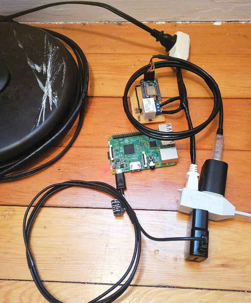
FIGURE 3. The Raspberry Pi and switch connected to the lamp.
This was the very first prototype. I plan to create a custom PCB (printed circuit board) through Kicad and OSHPark for the third revision. I will then dress up the switch with a custom 3D printed box that can be ordered from a local Staples after I make it look professional. Although the wireless switch is where the bulk of my interest and fascination lies, I can’t help but be impressed with the real time button state synchronization for the Android application.
Real Time Button State Synchronization
I ran into an issue after I finished building the switch and writing the Android app on my Linux machine. The toggle button on my wife’s and my phone was not synchronizing each time one of us pressed it. This was not a huge inconvenience, but it was a problem that I felt I needed to solve. It also seemed like it would be a really cool feature to have integrated into the project.
Unfortunately, the synchronization only works while on the LAN at the moment. This means that if someone leaves the house and they disconnect from the Wi-Fi, their toggle button will not synchronize with everyone else’s button once someone turns the lights on or off.
I’m working on a queuing system to fix this problem which will store the signal (on or off, in this case) and continue trying to send this signal to the IP address every few minutes until the user re-connects to the LAN.
To achieve this general concept of a centralized brain or system that could handle all of the signaling, I would need a Raspberry Pi. This is where the signals would be sent to once the toggle button is pressed on any one phone, and this is also where the signals would be distributed from and sent to all phones connected on the LAN who have my Android app installed.
The first thing I did was install a Rails server and MySQL database on the Raspberry Pi 3. The reason I chose Ruby on Rails is that the framework will allow me to permanently store each individual phone’s toggle button state, IP address, and any other relevant information I need to keep track of in a MySQL database. I can also send and receive POST (see sidebar) requests, and manipulate the incoming and outgoing data as well as the local database easily with the Ruby programming language, which is a favorite of mine!
The POST request method “requests” that a web server accept the data enclosed in the body of the request message; most likely for storing it. It is often used when uploading a file or when submitting a completed web form. In contrast, the HTTP GET request method retrieves information from the server.
The next step was setting up the registration system. The registration system works by sending the phone’s IP address to the Rails server (via POST request) once the phone initially installs my application while on the LAN. This keeps track of who has the application installed, but more importantly it allows the RPI to receive a signal and to traverse its database for registered IP addresses, then send a signal to whoever is connected to the LAN without an issue. So, when someone presses their toggle button to turn the lights on or off from the app, the Rails server will synchronize everyone up if permitted.
The POST request sent from the application when toggling the lights on or off is comprised of the user’s IP address and button state. Let’s have a look at the flowchart in Figure 4 to get a better picture of the synchronization flow of my framework.
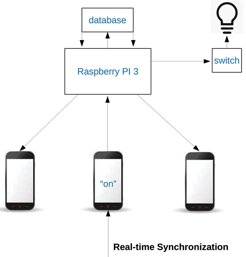
FIGURE 4. Real time button state synchronization flowchart.
The flowchart makes the concept of my framework seem straightforward, but it was a bit more complicated to achieve programmatically. The phone turning the lights on or off will send that signal to the Pi first. We already know that the Rails framework will then traverse the database and find all connected devices by IP address, but I feel I should reiterate to cover the full flow of my framework. The RaspPi 3 then sends out that same signal it received to a server running on the phones, which are constantly listening for incoming connections and messages.
Once the phone receives a signal, it then sends an intent to a private BroadcastReceiver class inside of the main Activity class. This is where the state of the toggle button is changed by updating the local SQLite3 database according to the signal it received. Figures 5 and 6 show some code samples to give you a better idea of what this looks like. The full code is available with the article downloads.
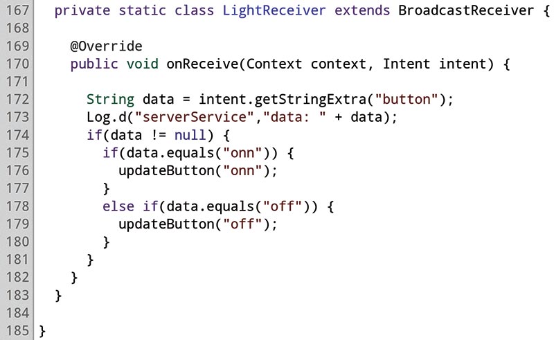
FIGURE 5. BroadcastReceiver code snippet.
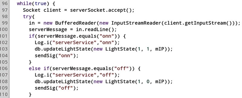
FIGURE 6. Server code snippet.
Automation Via Voice Recognition
The voice recognition is something I decided to do at the last minute. When I start a project that I really enjoy, I get so wrapped up in it that I just keep adding features and functionality until I get bored or I finish. (I have a lot of unfinished projects and I’m sure a lot of you readers do too.)
The voice recognition was a bit tricky to get working on the ARMv8 Raspbian device though, solely because the Pi 3 does not come with analog audio input. So, you are forced to buy an external audio USB adapter; so far, they have been hit or miss.
I ended up ordering a micro USB microphone from Amazon which didn’t work too well. The PocketSphinx Python API (application program interface) didn’t recognize the mic, which was due to system misconfiguration. Therefore, I ended up moving the voice recognition to an old laptop I never use that has an awesome built-in mic.
The voice recognition consists of a Python program that uses the PocketSphinx API, which is supposed to send a POST request to the rails server and synchronize the phones, as well as send a signal to the wireless switch. It instead sends a signal directly to the wireless breakout board attached directly to the light for now, and does not work with the central brain of the framework.
As you can see, the voice recognition portion of the project is a work in progress. Getting the speech recognition to be accurate is a bit tricky, too. It works well at the moment, but will need some fine-tuning before it’s fully deployable and ready. I would like to eventually get the speech recognition working on the RaspPi 3, but using my laptop to interface with the lights via voice will have to do for now.
The Switch Schematic and Disambiguation
The schematic of my wireless switch is shown in Figure 7. The wireless breakout board grounds out the BJT (bipolar junction transistor) in this common-emitter circuit and provides a 3.3 base voltage from one of its GPIO pins (which are the only dynamic and changeable factor on this board and/or circuit). The GPIO pin is either on or off, and this solely depends on the signal coming in from the phone that is controlled by the state of the toggle button.
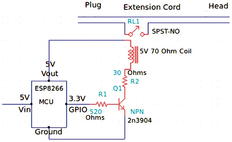
FIGURE 7. Switch schematic
The board also powers the relay coil with a five volt constant GPIO pin. This board even has a small server written in the C programming language that handles the incoming signals with general C compare functions that have bounds checking.
The BJT is probably my favorite component in this build and by far the most fascinating! Applying the right amount of current to the base and collector of the BJT will allow you to switch high current devices. The breakout board’s 3.3 volt GPIO pin is what’s used to saturate this small signal transistor.
The 520 ohm resistor at the base brings the current to the required 5 mA, as well as the 30 ohm resistor at the collector that brings the current to the required 50 mA needed to saturate the BJT. All of these factors can easily be calculated by using Ohm’s Law, of course.
The relay is almost an equally impressive device that has a coil that is magnetized once the coil is powered. Once this happens, it closes the armature on this normally-open SPST relay. It surprisingly only takes five volts to power the 70 ohm coil, which again is provided by the wireless breakout board. The other two contacts allow high current to flow through the relay (which is 110 VAC, in this case), but the relay is rated to handle much higher current if necessary.
Once the armature closes on the relay, it completes the extension cord’s circuit and allows power to flow.
Conclusion
Though it was a lot of work, I learned a lot by building this DIY home automation project. Though similar systems are available commercially, I wanted to re-create this particular device mainly because I have a fascination with wireless communication and any kind of switching like the BJTs perform. I’m also curious as to how they work. What better way to have fun and satisfy that curiosity than to recreate a device!
Additionally, I now have a design I can build on to create additional features like a door sensor to toggle the lights when I leave or enter my home. I had so much fun building this project, I now want to build another wireless switching mechanism to remotely start my car.
If you decide to build this project, please feel free to email me at [email protected] and let me know how it went. NV
Parts List
| QTY |
ITEM |
| 1 |
2N3904 small signal NPN BJT |
| 1 |
510 ohm carbon film resistor |
| 1 |
10 ohm carbon film resistor |
| 1 |
30 ohm carbon film resistor |
| 1 |
1N4004 flyback diode |
| 1 |
SPST-NO 5V 70 ohm coil relay |
| 1 |
Adafruit ESP8266 wireless breakout board |
| 1 |
FTDI cable |
| 1 |
Raspberry Pi 3 |
| 1 |
Extension cord |
| 1 |
Terminal block |
| 1 |
Printed circuit board |
WeMo is a series of products from Belkin (www.belkin.com) that enable users to control home electronics remotely. The product suite includes electrical plugs, motion sensors, light switches, cameras, light bulbs, and a mobile app.
Downloads
What’s in the zip?
Source Code - Note that this is a large fie (140MB) and will require a high speed internet connection.