I (like many Nuts & Volts readers) have spent many hours designing circuits based on microcontrollers, and then breadboarding the circuitry to verify proper operation before committing to building the actual project. In many of my breadboarding activities, would-be faults in my design turned out to be bad connections between the components or connections to the controller module itself.
To make matters worse, every time I’ve had to move my breadboard for one reason or another, I have had to start the debugging process all over again due to flakey connections.
So, the moral of this story is to limit the number of connections used during the breadboarding process (if possible) to help keep your project working and your sanity intact.
This, I believe, was a major motivation for the Dr. Duino Starter Kit (DDSK) for the Arduino Uno from drduino.com. This device, as will be described later, can make your breadboarding activities with the Arduino Uno more robust and trouble-free.
In addition, the DDSK can also be a useful tool in learning Arduino hardware and software design. Getting into microcontroller development for the first time can be a daunting undertaking and anything that can simplify the process will be welcomed by many.
I came up with numerous possibilities for how the DDSK could be used, including:
- As a trainer for people just getting into the Arduino ecosystem. Illustrate things like how you read a button's state, read an analog input, or how you use a digital output signal to light an LED.
- As a platform for writing an Arduino application's code before the associated custom hardware is available.
- To allow the piecemeal development of hardware that will eventually be turned into a custom Arduino shield.
- As a platform for testing a custom shield for proper operation.
There are lots of possible uses for this starter kit.
The Kit
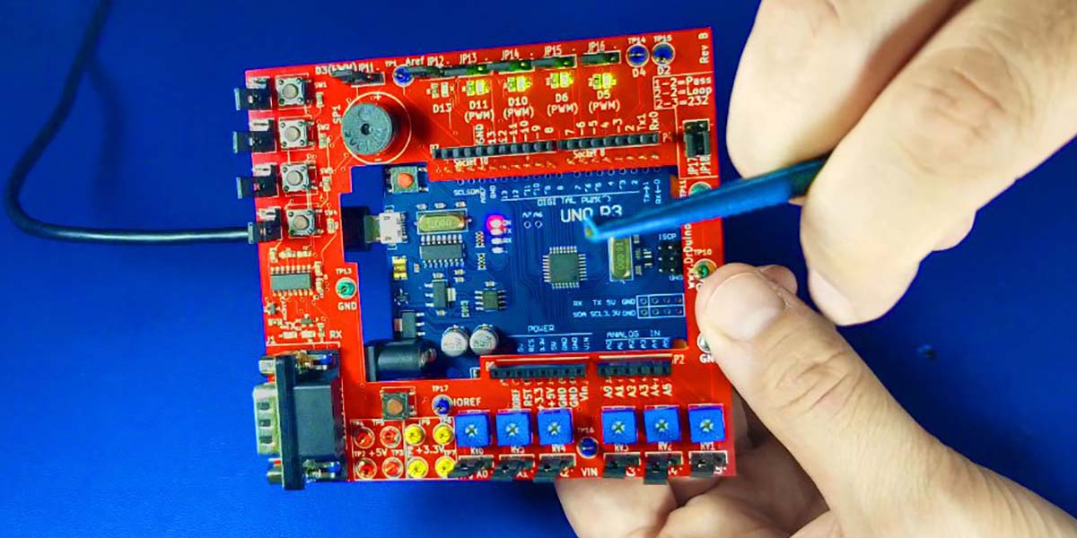
The starter kit consists of a 4-1/8” x 3-3/4” bright red printed circuit board (PCB) with a large rectangular hole in the middle. The PCB has a series of test points, pushbutton switches, LEDs, jumpers, and an RS-232 interface arrayed around the board's perimeter; refer to Figure 1.
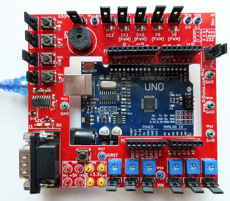
FIGURE 1. Fully assembled starter kit with an Arduino attached.
An Uno is plugged onto the bottom of the board after assembly is completed. The finished assembly has a two-tier arrangement as shown in Figure 2.
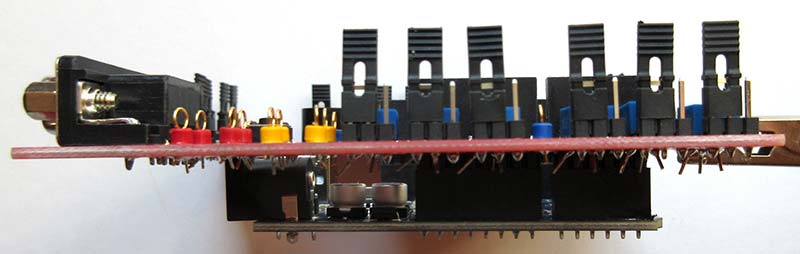
FIGURE 2. Two-tier construction of the starter kit with an Arduino plugged in underneath.
The kit arrived in the mail in a small envelope containing an Arduino Uno clone and a packet of thru-hole components that need to be manually soldered onto the PCB. All the hard-to-solder surface-mount components are already in place. Anyone with minimal soldering experience should have no trouble completing the starter kit's assembly.
Included with the kit of parts was a card with a link to the DrDuino website for downloading assembly instructions, documentation, and test code for exercising the starter kit once assembly has been completed. See Resources for the link.
The components provided with the kit seemed to be of good quality with the result being that the starter kit worked when I finished the construction.
The kit came with an eight LED NeoPixel strip, but there was no mention of this in the documentation. Not to worry! I put it to use in playing with the starter kit. More on this in a moment.
Hardware
The starter kit consists of four momentary pushbutton switches (five if you count the Arduino reset switch which is broken out separately from the Uno itself for easy access), five LEDs, six potentiometers, and a piezo speaker/buzzer.
Each Arduino pin is brought out to a three-pin header, allowing two possible jumper positions. Position 1 routes an I/O pin to either input sources on the starter kit itself (like pushbutton switches or potentiometers) or to onboard output devices like an LED or the piezo buzzer. Jumper position 2 routes the I/O pin to the shield connectors on the top of the starter kit where your custom hardware would be connected.
With this arrangement of jumpers on each I/O pin, you can use only the hardware on the DDSK itself; use a combination of hardware on the DDSK and custom hardware of your own design; or use only your custom hardware for development. Lots of flexibility for sure.
Test Software
The downloaded assembly instructions zip file contains both a PDF document detailing the assembly process, information on how to download the Arduino IDE (Integrated Development Environment), and how to load and run the provided test software for exercising the starter kit to verify its functionality.
Studying the test program sketch called DrDuino.ino will give you a very good idea of how the starter kit works. It will also give new Arduino programmers insight as to how Arduino code is structured.
With the test software sketch loaded and operational, pressing various pushbuttons will toggle LEDs on the DDSK. The serial monitor output from the IDE shows the value of the five analog inputs on the Arduino; these values change as the various onboard potentiometers are adjusted.
Finally, pressing pushbutton SW4 will cause a simple song to be played through the piezo buzzer/speaker.
A Simple Project
Since the NeoPixel strip was included with the kit, I thought I would put it to use. I connected the strip as follows:
| Strip Connection |
DDSK Pin Connections |
| GND |
GND |
| DIN |
13 |
| 4-7 VDC |
13 |
I then uploaded the following code to the starter kit:
/*
Example Code for the Dr. Duino Starter Kit for Arduino
This code implements a Larson Scanner with adjustable color and speed. A Larson scanner is a row of lights which illuminates in a back and forth manner. The Larson scanner is named after Glen A. Larson,the man responsible for producing both the original Battlestar Galactica and Knight Rider television shows where the scanners were used on the Cylons robots and on the Knight Rider car.
Potentiometer Analog Input Function
==========================================================
RV6 A0 Red Color Adjustment
RV5 A1 Green Color Adjustment
RV4 A2 Blue Color Adjustment
RV1 A5 Speed
NOTE: Make sure JP17 and JP18 on the starter kit are in the upper positions or completely removed or else you won't be able to download code to the starter kit.
*/
#include <Adafruit_NeoPixel.h>
// Make sure the jumper for pin 13 is towards the dot on JP12
#define NEOPIXEL_PIN 13
#define NEOPIXEL_COUNT 8
// Assign the color adjustment functions to the analog input potentiometers
#define RED_ADJ A0
#define GRN_ADJ A1
#define BLU_ADJ A2
// Assign the speed function to the analog input potentiometers
#define SPEED_ADJ A5
// Delay values to control speed
#define MIN_DELAY_MS 50
#define MAX_DELAY_MS 500
// Instantiate the NeoPixel driver
Adafruit_NeoPixel pixels(NEOPIXEL_COUNT, NEOPIXEL_PIN, NEO_GRB + NEO_KHZ800);
// Misc variables
unsigned long futureTime;
int pixelNumber;
bool countingUp;
// Setup code goes here
void setup() {
// Initialize NeoPixel object
pixels.begin();
// Initialize variables
futureTime = 0;
countingUp = true;
pixelNumber = 0;
}
// Main code goes here
void loop() {
// First read the user adjustable values for color and speed
// Read the color component values
byte red = analogRead(RED_ADJ);
byte grn = analogRead(GRN_ADJ);
byte blu = analogRead(BLU_ADJ);
// Combine to form a color value
uint32_t pixelColor = pixels.Color(red, grn, blu);
// Read the speed value
byte speedValue = analogRead(SPEED_ADJ);
// Map analog value 0..254 to MIN_DELAY_MS..MAX_DELAY_MS
int currentDelayMS = map(speedValue, 0, 254, MIN_DELAY_MS, MAX_DELAY_MS);
// Is it time for a change ?
if (futureTime < millis()) {
// Turn off all pixels
pixels.clear();
// Set the current pixel to the current color
pixels.setPixelColor(pixelNumber, pixelColor);
if (countingUp) {
pixelNumber++;
if (pixelNumber >= 7) {
countingUp = false;
}
} else {
pixelNumber--;
if (pixelNumber <= 0) {
countingUp = true;
}
}
// Make the affected pixel visible
pixels.show();
// Calculate future time for next change
futureTime = millis() + currentDelayMS;
}
}
The result is a Larson Scanner that is controllable both in color and scan speed. Refer to the code for the details.
Conclusions
There is utility in having the DDSK if one is doing a lot of Arduino Uno development. It can save time and frustration for the reasons I’ve discussed. In addition, the documentation talks about a private Facebook group and an available 12 lesson training video which I didn't have access to for this review.
For Arduino veterans like myself, this bonus material is unnecessary. For someone just coming up to speed with the Arduino, having a forum to ask specific questions and have lesson plans available would be invaluable.
I had hoped that a schematic of the starter kit circuit would be available, but none was included in the downloaded documentation or on the Dr. Duino website.
Finally, I could see this same approach being used with a Raspberry Pi, ESP8266, ESP32, or other microcontroller modules to aid in the development of custom hardware for those devices.
I have to say, the DDSK is a great way to get started. NV
Downloads
What’s in the zip?
Larson Scanner code