This modern take on the tube tester is a must for anyone who regularly works with tube type electronics.
A good tube tester is a must if you work regularly with tube-type gear, whether it’s vintage receivers or modern guitar amps. Virtually all the small-scale non-commercial options available are vintage conductance and transconductance meters that are growing long on the tooth. The vintage Hickok 600a is probably the most sought-after transconductance meter on the second-hand market, but the analysis is limited to what can be displayed on an analog output meter.
A modern option to vintage analog tube checkers is the eTracer: a USB peripheral that transforms a Windows laptop into a full-featured vacuum tube curve tracer (Figure 1).
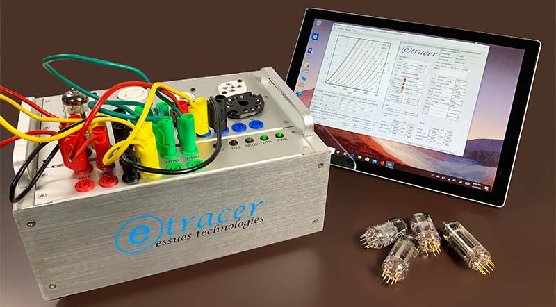
FIGURE 1. eTracer running on Windows 10 laptop.
The eTracer hardware is available in various kit configurations with a motherboard ($350), power supply ($30), and chassis ($200), directly from the manufacturer: Essues Co. Ltd. (www.essues.com) in Taiwan.
In addition to the hardware, you’ll also need a Windows-only software license ($500), bringing the total cost of a kit to between $850 and $1,080.
I ordered the full basic kit ($1,080) with two-day DHL shipping ($80) and spent an enjoyable weekend assembling and testing the eTracer. Over the past year, I’ve used it to test vacuum tubes from amateur radio receivers and amplifiers, to vintage stereo receivers and guitar amps. Although I have no intention of selling my refurbished Hickok 600a (the subject of another article), the eTester is now my go-to tube tester.
Specifications and Documentation
There isn’t a specification list per se. Objectively, I can say that the 26x19x10 cm (10 x 7.5 x 4 inch) aluminum chassis accepts a standard 120 VAC cord and a USB cord from your Windows 10 laptop or desktop PC. The 30W power supply can furnish 1.5V-27V at 3A for tube filaments or heaters, 0-750 VDC at 300 mA plate supply, and (-) 170 VDC for the grid.
Documentation consists of three PDF manuals that can be downloaded from the eTracer site: a chassis manual; a PCB manual; and a software manual. The chassis manual describes how to assemble the chassis and how to wire the tube sockets. The PCB manual provides an overview of the motherboard and how to wire the jacks. The software manual describes how to install and configure the software.
By far, the best documentation is a series of YouTube videos created by the developer of the eTracer, C. Chang, under the channel name “C Chang.” Another excellent reference is a three-part series called “Building an eTracer Vacuum Tube Tester” by Blueglow Electronics.
The Build
The build of this kit is straightforward. Given the ample printed manuals and online video, if you can handle a soldering iron and a Phillips head screwdriver, then you can handle this kit.
A pre-built option is available ($150), but then the eTracer becomes little more than a black box that you won’t know how to maintain. The build process — shown in Figures 2-10 — consists of a few easy steps:
- Unpack the DHL envelope to reveal the kit contents (Figure 2). Assuming you ordered the full kit, you should have the aluminum chassis panels, the fully populated motherboard, the 30W power supply, a bag of tube sockets and jacks, and a bag of banana jumpers and two spools of Teflon-coated white wire.
- Attach the BNC jacks to the aluminum chassis (Figure 3). The kit includes a tool to tighten the rings around each jack.
- Attach the tube sockets to the aluminum chassis (Figure 4). An oddity of this kit is that you need to supply the hardware to mount the tube sockets. I used black oxide finish #4-40 machine screws, flat washers, and lock washers from BoltDepot.com. You can order bags of 100 pieces each of screws, washers, and lock washers for $23, including tax and shipping, and have a supply of hardware for several more projects.
- Wire the BNC jacks to their corresponding tube socket pins (Figure 5). For example, BNC jack #1 is connected to pin #1 of every tube socket. Note that, instead of using the supplied white Teflon coated wire for this stage of the build, I used my own silicone coated wire, with a unique color for each BNN jack number. Also, note the ferrite beads used on the wires between the tube sockets. Once the wiring was complete, I used silicone sealant to stabilize the wires and prevent the ferrite beads from moving.
- Mount the banana jacks to the breakout panel (Figure 6). Wire the banana jacks in pairs to a six-pin Molex connector that will mate with the motherboard. You can use a dedicated Molex crimp tool to make the six crimps, or simply use a pair of needle-nose pliers.
- Mount the indicator LEDs to the breakout panel (Figure 7). Note the polarity of each LED and — if you have spare color wire available — use it to indicate polarity. For example, in my case, I used a red wire for the anode of each LED.
- Assemble the motherboard, chassis, power supply, fan, and breakout panel, inserting the Molex connectors from the banana jacks and LED indicators into the motherboard (Figures 8 and 9). If you want a cooling fan, you’ll have to supply your own. I picked up an 80 mm x 25 mm GDSTIME 8025B 12V dual bearing brushless fan from Amazon for $11. The 2,800 RPM fan provides more than adequate air flow of 43.6 CFM.
- Attach a pair of optional aluminum handles (Figure 8). Although not part of the kit, l like the idea of handles on “flat” equipment to provide protection to the sockets and to make the little unit easier to grab without leaving fingerprints and dirt on the top panel. I found a set of plain aluminum pulls on eBay for $5 that fit the look and dimensions of the eTracer.
- Add the “sticky” pressed paper cover to protect the motherboard from showers of metal slivers (Figure 10). Repeatedly inserting tubes into the tube sockets guarantees small slivers of the pins and/or tubes are generated and fall into the sticky board. Plan to clean the sticky board after several months of heavy use.
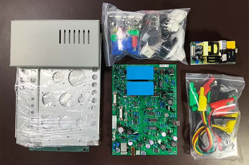
FIGURE 2. As received from vendor.
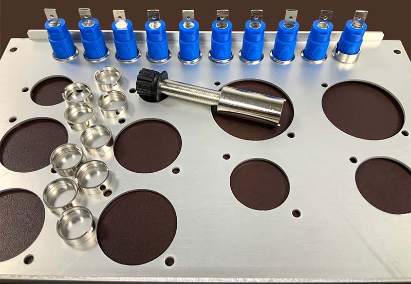
FIGURE 3. Mounting banana jacks.
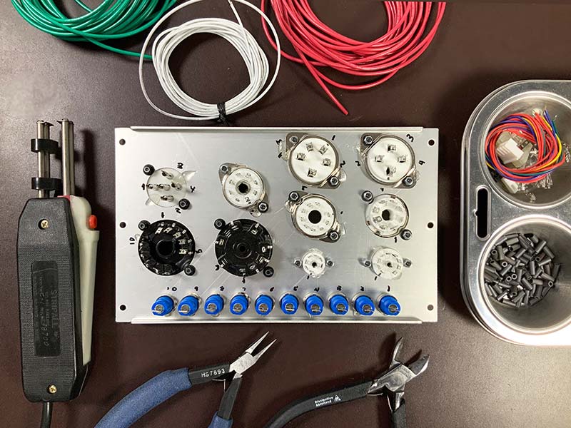
FIGURE 4. Beginning tube socket wiring.
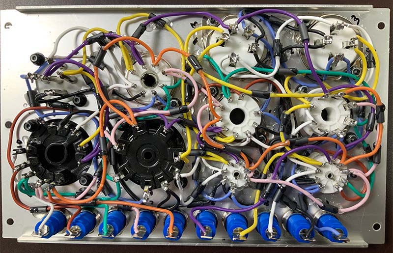
FIGURE 5. Wiring tube sockets complete.
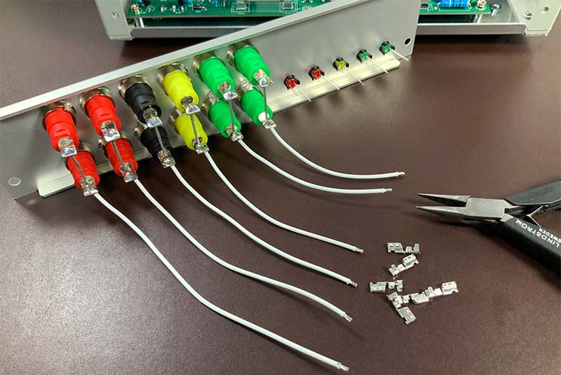
FIGURE 6. Top panel wiring.
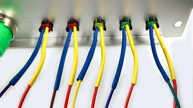
FIGURE 7. LED mounting.
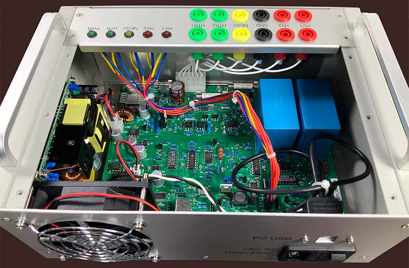
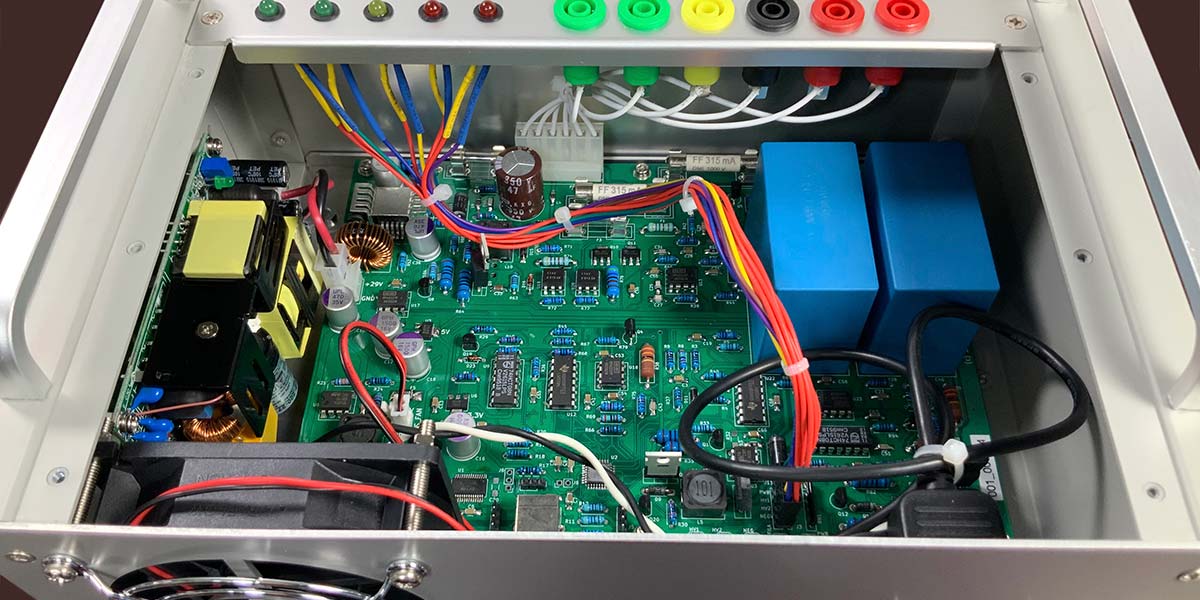
FIGURE 8. Wiring complete, top view.
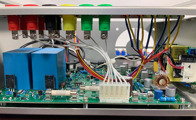
FIGURE 9. Wiring complete, side view.
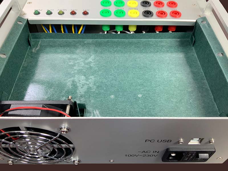
FIGURE 10. Sticky barrier installed.
Software Installation
Software installation is straightforward. Download the installer with executable and tube definition files from the eTracer website. Finalize the installation by copying the license file that you’ll receive by email when you pay the license fee into same folder as the executable.
Use Case
Following a short calibration routine, the eTracer is ready for action. To illustrate the power of the eTracer, let’s test two triodes in a single 12AX7. After connecting the USB cable and powering up the eTracer and your Windows 10 machine, launch eTracer. Connect the eTracer to an open COM port on your Windows machine and load the configuration file “12AX7” from the library of tube definitions.
Next, following the tube configuration table in the main interface (see Figure 11),
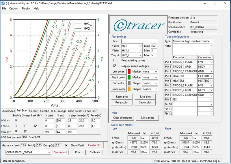
FIGURE 11. Quick Scan interface.
use the short banana cables to make the following connections:
Pin 1 - HV1
Pin 2 - NEGV
Pin 3 - GND
Pin 4 - Heater1
Pin 5 - Heater2
Pin 6 - HV2
Pin 7 - NEGV
Pin 8 - GND
The most time-consuming aspect of running the eTracer is making the connections with the cables. After that, it’s simply a matter of selecting a test — each of which is described fully in the software manual — from among seven tabs:
Quick Scan - Quiescent current, plate AC resistance (rp), transconductance (gm), and voltage amplification (mu).
Full Scan - Generate family of plate current curves with different grid biases against incrementing plate voltage.
Corners - Test for failure at extreme voltage values or “corners.”
Combo - Perform a combination of Quick Scan, Full Scan, and Corners.
H-C Leakage - Test for heater-cathode leakage.
Basic Params - Basic parameters display allows the user to explore rp, mu, and gm with the mouse over the graph.
Load Line - User can drag mouse across graph to change the load line.
Each of these tests or analyses takes time and study to fully appreciate. In this regard, consider eTracer a physics laboratory designed to explore every nuance of vacuum tubes. You’ll need to spend time on the Web or with a good textbook on tubes to fully appreciate the power of eTracer. For now, let’s take a high-level tour of eTracer’s capabilities.
To illustrate a Full Scan, select the “Full Scan” tab and plug in the 12AX7 into the appropriate socket (only one socket fits the 12AX7). Click on the “Heater On” button. After 30 seconds or so, click on the “Run” button. After about two minutes, eTracer will generate a family of curves for each of the two triodes in the 12AX7 (see Figure 12).
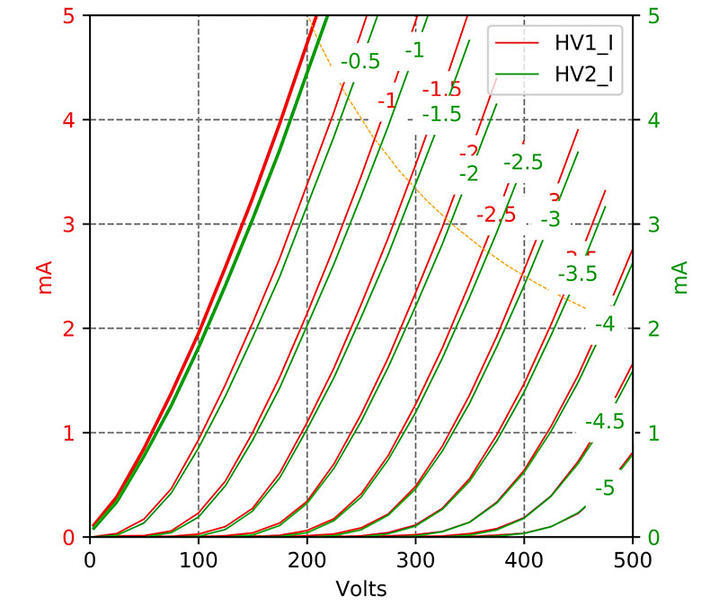
FIGURE 12. Quick Scan graph.
eTracer will also generate a table of Quick Scan results. For example, the left triode in my test had a transconductance (gm) of 2,000 and mu of 97.6, compared to a gm of 1,824 and mu of 94.2 for the triode on the right (again see Figure 11).
Next, let’s try a combination scan by selecting the “Combo” or combination tab (Figure 13) and click on the “Run” button.
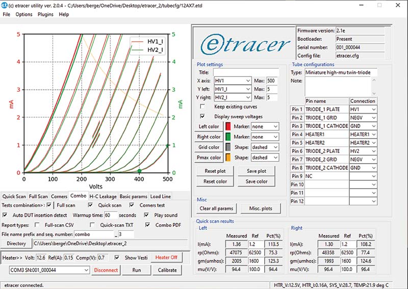
FIGURE 13. Combo Scan interface.
As before, eTracer generates a family of curves (Figure 14), this time with added information including a Corners test. The two green points at 400V and 500V are the result of the Corners test.
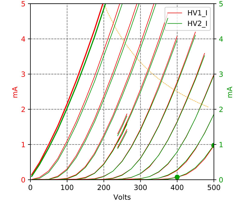
FIGURE 14. Combo Scan graph.
Conclusion
The eTracer is an expensive but powerful tool with a modest learning curve. The kit is easy to assemble over a weekend and the software can be mastered over several days. If you’re serious about working with and understanding vacuum tubes, then the eTracer is worth considering as part of your workbench arsenal. NV