I recently read two articles about linear-feedback shift registers, which are shift registers with some of their outputs fed back to the input for generating cyclic redundancy check (CRC) bits or random numbers. Short of actually building these (and other digital) circuits, it’s sometimes hard to check that they do what they claim to do. Here's an interesting and simple technique for simulating these circuits on a computer using a spreadsheet program.
It doesn’t have to be an expensive or powerful spreadsheet program. For the examples that follow, I'll use Excel.
The Inverter
Figure 1 shows the basic idea. Looking at an inverter — such as a 7404 — in the TTL manual, you’ll often see the inputs and outputs labelled as In and Out, or perhaps A and B. Simply label them A1 and B1, and right away, you get the idea: Just use cell A1 in the spreadsheet for the input and cell B1 for the output. There’s nothing magic about these two cells, as you could use any two cells in the spreadsheet. Now all you have to do is put the right formula into cell B1, so it’s always the opposite of A1, and you’re done.

FIGURE 1. A simple inverter.
For the inverter in Figure 1, if the input is a 0, then the output is a 1, and if the input is 1, then the output is 0 (you have to use 0 and 1, because it won’t work if you try to use H and L or True and False instead). There are two ways to do this. The simplest is to write this as the simple formula:
Output = 1 - Input
In other words, in the spreadsheet, cell B1 should be equal to one minus whatever is in cell A1: 1 minus 0 is 1, whereas 1 minus 1 is 0. The formula then becomes:
B1 = 1 - A1
In Excel, you’d type =1-A1 into cell B1 (with the equal sign); whereas, in most other spreadsheets, it would be just 1-A1. Make sure to check the exact format for whichever spreadsheet you are using. Another way is to use the spreadsheet’s IF function, like this:
B1 = IF(A1 = 0, 1, 0)
The parentheses contain three arguments: a test; what to do if the test is correct; and what to do if it isn’t. In this case, it says, “if A1=0, then make this cell equal to 1, otherwise make it 0.” For obvious reasons, I prefer to use the “one minus” approach.
Figure 2 shows some other simple gates, but let’s do them one at a time.
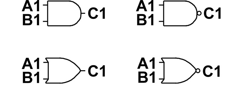
FIGURE 2. Simple digital gates.
The AND Gate
For the AND gate at the top left corner of Figure 2, the truth table (which describes how it works) is shown in Table 1, from which we can see that the output is just the product of the two inputs: a simple multiplication. So, the formula to put into cell C1 is A1 x B1.
| A1 |
B1 |
C1 |
| 0 |
0 |
0 |
| 0 |
1 |
0 |
| 1 |
0 |
0 |
| 1 |
1 |
1 |
TABLE 1.
Some spreadsheets actually have functions for doing simple logical operations. Excel insists on using words like TRUE and FALSE, so that is not very useful to us, but 123 and others use ones and zeroes. The corresponding syntax for this formula in 123 and some others would be +A1#AND#B1. Don’t bother — A1 x B1 is much simpler.
The NAND Gate
In the NAND gate at the top right corner of Figure 2, the output is similar to that of the AND, but inverted. The equation:
C1 = 1 - (A1 x B1)
should just about do it, since the “1-” part does the inversion just as in the inverter.
The OR Gate
The truth table for the OR is shown in Table 2. The easiest way to implement this is with an IF, like this:
C1 = IF(A1 + B1 = 0, 0, 1)
which says that if the two inputs add up to zero (which means they are both zero), make the output a 0, otherwise make it a 1.
| A1 |
B1 |
C1 |
| 0 |
0 |
0 |
| 0 |
1 |
1 |
| 1 |
0 |
1 |
| 1 |
1 |
1 |
TABLE 2.
The NOR Gate
The NOR is just the opposite of an OR gate (Table 3). Here again, the easiest way to do it is to use an IF:
C1 = IF(A1 + B1 = 0, 1, 0)
which is the same as the OR, except that it flips the 0 and 1 in the output.
| A1 |
B1 |
C1 |
| 0 |
0 |
1 |
| 0 |
1 |
0 |
| 1 |
0 |
0 |
| 1 |
1 |
0 |
TABLE 3.
XOR — The Exclusive OR
Figure 3 shows the Exclusive OR gate, which has the truth table shown in Table 4. The word exclusive means that the output is a 1 if either A1 or B1 is 1, but not both.
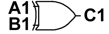
FIGURE 3. The Exclusive OR gate.
| A1 |
B1 |
C1 |
| 0 |
0 |
0 |
| 0 |
1 |
1 |
| 1 |
0 |
1 |
| 1 |
1 |
0 |
TABLE 4.
If you use the spreadsheet’s IF statement, the IF reads:
IF(A1 = B1, 0, 1)
which just means that, if the two inputs are the same, then the output is 0; if they are not the same, then the output is 1.
Alternatively, you could also write:
C1 = ABS(A1 - B1)
which tells the spreadsheet that the output is the difference between A1 and B1; in case A1-B1 is -1, then the ABS function just changes it into +1.
Handling Flip-Flops
Flip-flops are interesting because they create some special problems that require unique solutions. Figure 4 shows a simple flip-flop made from two NAND gates.
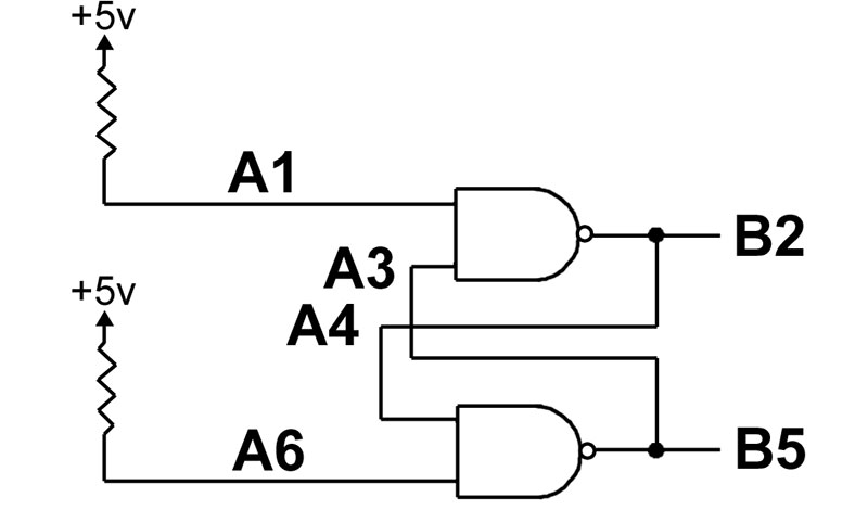
FIGURE 4. Flip-flop made of gates.
As you know, flip-flops have two outputs, normally labelled Q and Q’ (Q’ is pronounced Q not or not Q), which are always opposites of each other. We say that the flip-flop is set if Q is a 1 (while Q’ is 0), and the flip-flop is reset if Q is a 0 (while Q’ is a 1). If B2 is Q and B5 is Q’ in Figure 4, then we can set the flip-flop by temporarily grounding input A1 or reset it by temporarily grounding input A6. (The two resistors make both inputs normally 1.)
Figure 5 shows the spreadsheet for this circuit as it would look in Excel; on the left are the formulas (Excel shows them when you press CTRL and ` (the reverse apostrophe at the top left of the keyboard), while on the right, it shows what happens.
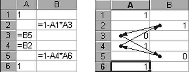
FIGURE 5. Excel spreadsheet for the flip-flop of Figure 4.
The formulas at the left of Figure 5 follow the circuit almost exactly. For example, cells A1 and A6 are both equal to 1, cell B2 is the NAND of cells A1 and A3, and so on. The problem shows up on the right, so Excel inserts a bunch of arrows linking the cells.
The catch is that the circuit uses circular reasoning: A3 depends on B2, which depends on A4, which depends on B5, which depends on A3, and so on. The actual outputs (i.e., whether the flip-flop is set or reset) depend on timing and what happened most recently.
Excel doesn’t know what to do with this. It turns out that Excel is too smart; older spreadsheets (such as 123) will do what you want as long as you press the “recalculate” key a few times each time you change an input, whereas Excel won’t. To handle this, we have to bring time into the spreadsheet — think of before and after. Common JK or Type D flip-flops have a clock input. Think of the inputs as they existed before the clock pulse and the outputs as they exist after the clock pulse. The trick for handling flip-flops in a spreadsheet is to bring in time by using the sheet’s rows.
For example, if Row 1 describes things before a clock pulse, then Row 2 describes things after it. And if there is another clock pulse afterward, then Row 3 describes what happens after that, and so on.
In other words, time goes down in the sheet.
Mod 3 Counter
The best way to show this is with an example. Figure 6 shows a synchronous mod-3 counter that counts 0...1...2...0...1...2... and so on. At any instant of time, the flip-flops get certain inputs and provide certain outputs, but nothing happens until a clock pulse arrives. Let’s see how this is done.
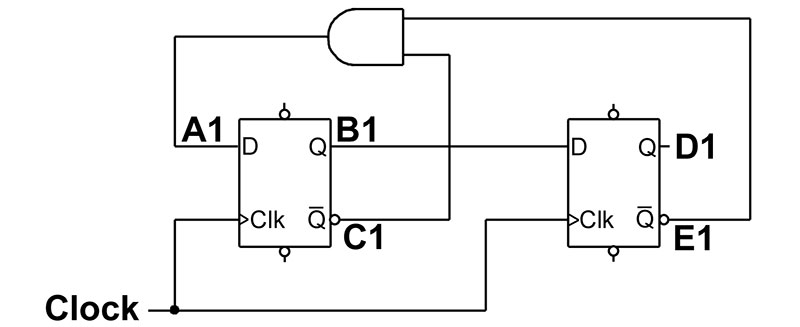
FIGURE 6. Mod-3 synchronous counter.
Look at Figure 7 as we fill in the spreadsheet formulas in the following sequence:
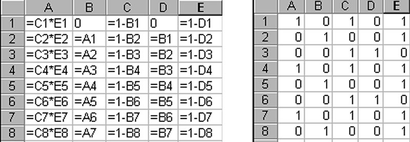
FIGURE 7. Spreadsheet for the mod-3 counter of Figure 6.
To begin, assume that the two flip-flops both start at the reset. Thus, the two Q outputs should be zero, while the two Q’ should be their opposites. Thus we fill in:
B1 = 0
C1 = 1 - B1
D1 = 0
E1 = 1 - D1
Next, the D input into the first flip-flop is just C1 and E1 ANDed together, so:
A1= C1 x E1
The top row of the sheet is now complete; it describes the starting, or initial, conditions. Let’s now assume that a clock pulse comes in. Row 1 describes the situation before the clock pulse, so let’s use Row 2 to describe the signals after the clock pulse.
At a clock pulse, the D input into a flip-flop determines whether the flip-flop will set or reset; that is, the Q output after the clock (in cell B2) will be the same as the D was before the clock (in cell A1). The same occurs with the second flip-flop, so we fill in:
B2 = A1
D2 = B1
At any time, the Q’ outputs will still be the opposites of Q, so we can either write:
C2 = 1 - B2
E2 = 1 - D2
or else just copy the C and E columns all the way down the sheet (and let the spreadsheet update the row numbers). Finally, the output of the gate (and D input to the first flip-flop) is still the ANDed signal from Columns C and E, so we can either write:
A2 = C2 x E2
or else again just copy the A column down the sheet.
At this point, we’re almost done. The second row is finished, and now all we have to do is copy the remaining entries from Row 2 down as far as you want to go.
The results are as shown in Figure 7. To interpret it, look at the B and D columns; these are the two Q outputs from the flip-flops. Column D is most significant while B is least, so we see that the counter outputs are:
00 = 0
01 = 1
10 = 2
00 = 0
01 = 1
... and so on.
The CRC Generator
Now that you’ve gotten the idea, let’s apply the material to two real world problems. The first is a CRC generator which appeared way back in the July 2004 issue of Nuts & Volts in an article by James Antonakos on error detection in digital data. The circuit (shown in Figure 8) uses a shift register with its output fed back into the inputs through two XOR gates.
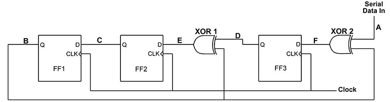
FIGURE 8. The CRC circuit from the July 2004 issue of Nuts & Volts.
Figure 9 shows the resulting spreadsheet, with the formulas on the left and actual results on the right. The letters A through F in Figure 8 tell us which column of the sheet has that signal.
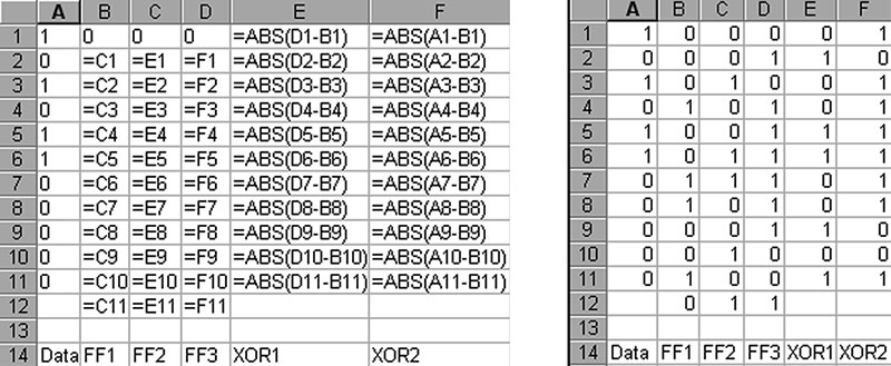
FIGURE 9. The spreadsheet for the CRC circuit of Figure 8.
Rather than explain every cell of the sheet, let’s explain what the circuit does. The general idea is this: When digital data is sent from one place to another, a CRC generator is used at the sending end to generate a check number, which is then attached to the end of the outgoing data. At the receiving end, an identical CRC generator gets the data plus the CRC check digits from the sender and tests whether there are any errors. If there are no errors, the receiver’s CRC circuit outputs all zeroes; if the output is non-zero, then there was an error.
Let’s assume that the outgoing data is the eight-bit number 10101100, and that the CRC check number will consist of three bits. The sender starts with the circuit of Figure 8, and the initial condition that all three flip-flops are reset to 000; this is the 000 in cells B1 through D1.
In order to generate the three-bit CRC number, the sender appends an extra three 000 bits to the end of the data stream and sends it into the input labeled SERIAL DATA IN of Figure 8 in its own CRC generator. This string of 10101100000 (a total of 11 bits) appears in Column A of the spreadsheet. There is a clock pulse after each input bit, which brings us down one row of the spreadsheet.
At each row, the spreadsheet calculates the outputs of the three flip-flops (Columns B through D) and the two XOR gates (Columns E and F). These signals determine what will happen in the next row, after the clock pulse.
At the very end, whatever is left in the three flip-flops (in Row 12) is the CRC number which is appended to the outgoing data. In this particular case, the CRC check number is 011. So, the actual data going from the sender to the receiver will be the original data 10101100, plus the extra 011 from its own CRC circuit. Thus, the sender’s CRC circuit gets the data, plus three zeroes, whereas the receiver’s CRC circuit gets the data, plus 011 (assuming there were no errors).
Now, let’s assume that the receiver has the exact same CRC circuit, so we can use the same spreadsheet as before, with one change. Whereas the bottom three bits in the A column of the sender were 000, in the receiver they will be 011. Try it in your spreadsheet: Change the 000 in cells A9 through A11 to 011 and the three bits in Row 12 become 000, signalling that no error occurred.
Now try changing one or more of the bits in column A to simulate an error in transmission; you will see that the last row is no longer 000. This tells the receiver that there was a transmission error in the data.
A Random-Number Generator
Figure 10 shows a random-number generator taken from another previous article in Nuts & Volts.
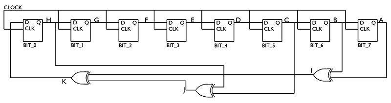
FIGURE 10. Random number generator from a previous article.
Starting with an initial value called the seed, the circuit is supposed to cycle through some sequence of operations and output a string of random eight-bit numbers. These numbers are the contents of the eight flip-flops after every clock pulse.
A fairly simple, yet useful, definition of “random” would be that a number is random if even an intelligent observer, knowing the past numbers in the sequence, can’t guess what the next number will be.
The numbers output by most random-number generators are actually called pseudo-random because they are not truly random — they only look it. They are predictable if you know the circuit or process that produced them. Still, for many applications, pseudo-random numbers are good enough.
The circuit is somewhat similar to the CRC circuit. It also has a shift register with some XOR gates to feed its outputs back into the input. But this time, there is only a clock input and no data input. As before, I’ve added letters to the diagram to show which signal will be in which column of the spreadsheet.
Figures 11 and 12 show the formulas and results of this spreadsheet (I added an extra column at the right in Figure 12 that converts the eight-bit binary output in Columns A through H into hexadecimal).
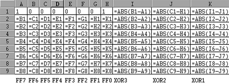
FIGURE 11. The “random” number generator formulas.
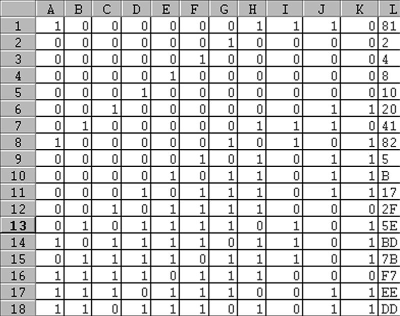
FIGURE 12. The “random” number generator results.
The initial seed is what would be in the flip-flops at the start. It is at the top in cells A1 through H1. Starting with any seed, the circuit should produce 255 numbers before it starts to repeat itself. In order to get the same sequence of numbers as the Nuts & Volts article, I used an initial seed of 10000001, which is hexadecimal 81. Using this as a starting value, the circuit outputs the following sequence (starting with Row 2):
00000010 = hex 02
00000100 = hex 04
00001000 = hex 08
00010000 = hex 10
00100000 = hex 20
01000001 = hex 41
10000010 = hex 82
00000101 = hex 05
The problem is that these numbers are not very random at all — the bits in consecutive numbers just shift to the left, with an occasional new “1” appearing at the right end. Hence, if you know the previous numbers, you have a slightly better-than 50 percent chance of guessing the next number.
You always know the first seven bits of it, and so all you need to do is take a guess as to whether the last bit will be a zero or a one. But that’s another story.
The point is that using a spreadsheet to analyze this circuit and looking at the bits output at each clock pulse is very instructive. In this case, it allows us to see that the circuit has a defect which would not be very noticeable if we just looked at the hexadecimal output.
One Last Comment
This is a simple and cheap technique. Even though I used Excel in my examples, you can use any of the free or shareware spreadsheet programs out there to do exactly the same thing. No exotic spreadsheet functions are needed. NV