As an experimenter, I use wall warts all the time to power circuit boards, microcontroller boards, and even finished projects. However, during the checkout phase of a new circuit, wall warts present a problem. How do you measure their output when they’re plugged into a board or project box? Figure 1 illustrates the problem and Figure 2 presents the solution.
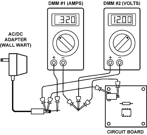
FIGURE 1. The old way to measure voltage and current from a wall wart.
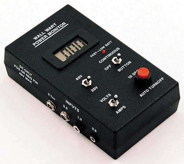
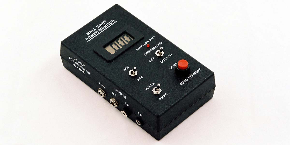
FIGURE 2. The new self-contained in-line Wall Wart Power Monitor displays readings either continuously or at the touch of a button.
The Need
Why is there a need to measure the output of a wall wart, you might ask? There are two reasons: current and voltage. For example, is your circuit drawing the predicted amount of current? Is the current more than the wall wart is designed to handle? Is the voltage sufficient to drive any downstream regulators under full load conditions? Or, is the voltage too high, putting a large heat burden on the regulators?
That’s where the unit described in this article comes in. I call it the Wall Wart Power Monitor. It’s a self-contained, in-line, battery powered unit that measures both DC current and voltage. It accepts four of the most common types of wall wart plugs and, in turn, has four identical output plugs, ready to hook to your project.
Requirements
Coming from a background in the aerospace industry, when I start a new project I immediately think of generating a 200 page System Requirements document. Since I’m retired now, I have to keep myself in check. A list of basic requirements is still useful, so, here goes.
Requirements:
- Low cost.
- Compact size.
- Self-contained (no external power required).
- Can measure wall wart DC outputs from 3.3 VDC to 24 VDC.
- Can measure currents of at least two amps.
- Interfaces with the most common wall wart connectors.
- Can handle both positive and negative pins.
- If battery powered, the battery must last for several months.
Other Desirable Features:
- Uses power from the wall wart to drive the circuitry.
- Has an LED to indicate when unit is on.
- Uses surface-mount components to reduce size.
Circuit Design
The first item to select was the LCD voltmeter. Digi-Key listed three models of Martel’s low-cost V-Series voltmeters for under $30. Let’s look at the specs: +-200 mv full scale, with auto-zero and auto-polarity. User selectable decimal points. Three samples per second. Power requirements are 7-12V at a paltry 1 mA. Three sizes of numerals are available: 0.25”, 0.50,” and 0.60”. I chose the 0.50” size so I could read it across the bench.
Unfortunately, these meters have a downside. They require an isolated power supply, like a 9V battery. You are not allowed to connect the minus (or plus) of the power supply to either input, i.e., a common ground, due to the V-Series’ internal circuitry. There are tricks you can use — like plus and minus supplies — but that’s usually not practical. One nifty solution would be to employ an isolated DC-DC converter, which I’ll discuss later on.
Now ... what about battery life? A quick search of the Internet for the specs on a 9V Duracell Coppertop showed a life of 250 hrs with a 2 mA load and 7V cutoff. The Martel unit only uses 1 mA which means the service life would be approximately 500 hrs. Therefore, if it was used for four hrs/day, we could expect a lifetime of 125 days. Sounds good.
Then, I had a brainstorm. When I’m checking out a circuit, I seldom need to read the voltage or current continuously; a brief look now and then is usually enough. This would also extend the battery life. So, I added the auto-turnoff circuit shown in Figure 3. In operation, each time the button is pushed, it charges the 10 mF capacitor, turning on the FET and LCD. When the button is released, the one meg resistor slowly discharges the cap until it falls below the Gate Threshold Voltage (VGS(th)) of the FET and turns off the LCD.
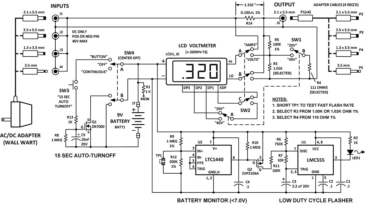
FIGURE 3. Schematic of the monitor features, auto-turnoff, battery monitor, and LED flasher circuits.
Since the FET was being used as a switch, I wondered how much current — if any — might still be flowing when it’s turned off. Would it drain the battery? A check of the spec sheet showed a maximum Zero Gate Voltage Drain Current (IDSS) of just 1 µA — not a problem.
I double-checked the auto-turnoff circuit on a solderless breadboard to make sure my calculations and assumptions were valid.
This brings us to the DC-DC converter that I mentioned earlier. The idea was to use a small amount of power (1 mA) from the wall wart to power the LCD. The biggest problem was that the input voltage could vary from 3.3 VDC to 24 VDC, which is a major stretch for most DC-DC converters.
So, I poured over the catalogs looking for an isolated converter with just the right mix of specs. To make a long story short, the design became way too complicated. It looked like I would need to add a diode bridge (to handle positive and negative pins), pre-regulator, small heatsink, DC-DC converter, and raise the minimum input voltage to 5V. Too messy. The KISS principle won the day. Battery power was the best choice!
Bells and Whistles
Just when I thought the design was pinned down, I realized there were times when I wanted to leave the monitor on for a half hour or so, not just 15 seconds. For example, when I’m checking out a GPS module. So, I added a new switch for “continuous” operation, designated as SW4 in Figure 3. I chose a center-off switch so if the monitor was not going to be used for an extended period, the battery could be totally disconnected.
However, the “continuous” feature presented a new problem. The monitor could inadvertently be left on and I would never know it except for the dim LCD readout. So, I added one of the “desired” features: an LED. But wait! LEDs draw too much current, you say! To counter that, I changed the design to a low duty-cycle blinking LED. I considered using a 2N6028 PUT or a CMOS LMC555 to generate the pulses. They both consumed about the same amount of current — 200 µA — but the 555 would be easier to control. R6 and R7 were selected so the rate would be ~1 Hz with a duty cycle of 2%. The average current for the LED would be around 100 µA. Perfect.
The next challenge was to add a battery monitor so the user would know when to change the battery. I wired up a low-power (4 µA) LTC1440 comparator on the test breadboard and selected R9 and R12 to switch at ~7.0V. The formula is Vthresh = 1.182((R9+R12)/R12). Now, here’s the really cool part. Instead of adding yet another LED, I tried to make the comparator increase the flash rate of the existing LED to indicate a low battery.
Again, more additions — R10, Q2, and R11. When the battery drops below 7.0V, the LTC1440 output goes low, turning on the P-channel FET which puts the 100K (R11) in parallel with R6, and raises the rate up to about 5 Hz. Bottom line: 1 Hz = Unit on; 5 Hz = Change the battery.
Even with all these bells and whistles added to the breadboard, the final measured average drain on the battery was only 1,250 µA. Acceptable!
Lastly, I added a “range” switch (SW1) to handle wall warts over 20V. SW1 changes the voltage divider — R5 and R3 — from 100:1 to 1,000:1. Now, the meter reads either 0-19.99V or 0-199.9V. Changing the decimal points was easy too; just add an extra pole to SW1 and SW2.
There was still a question in my mind regarding the best way to label the new range switch. Should it be 20V and 200V, like a conventional digital multimeter, or something else? I hesitated to use the 200V label because the monitor was designed to measure a maximum of 24V — not high voltages. So, I settled on 20V and 40V. Plus, I added a label — “40V MAX” — near the input connectors to specify the upper limit.
Construction
Okay. Now that the design was frozen, it was time to package it. In the Digi-Key catalog, I selected a wrinkle-finish black Serpac SR251 enclosure because it had an internal battery box and plenty of room for all the switches and their labels. Then, I drilled the holes, applied the white rubdown letters, and sprayed it with Krylon Matte Finish #1311. DISASTER! The finish looked terrible — all mottled and uneven. I was sick. I checked the spray can. It definitely was compatible with plastics and had worked on other projects in the past. What was going on?
Fortunately, I had another Serpac SR251 box so I started all over again, new holes, new lettering. What a pain! Then, I took an old spare Serpac box and sprayed it with three different plastic-compatible Krylon sprays: Matte Finish #1311, Low Odor Clear Finish (Matte), and Low Odor Clear Finish (Gloss). The Low Odor Clear Finish (Matte) looked the best, so that’s what I used on the box shown in Figure 2. However, please do your own tests before using any of these sprays on your next project.
As for the PCB, I considered using surface-mount components, but there was plenty of room between the switches for through-hole parts, as illustrated in Figure 4. I included a test point (TP1) so the low battery condition could be tested.
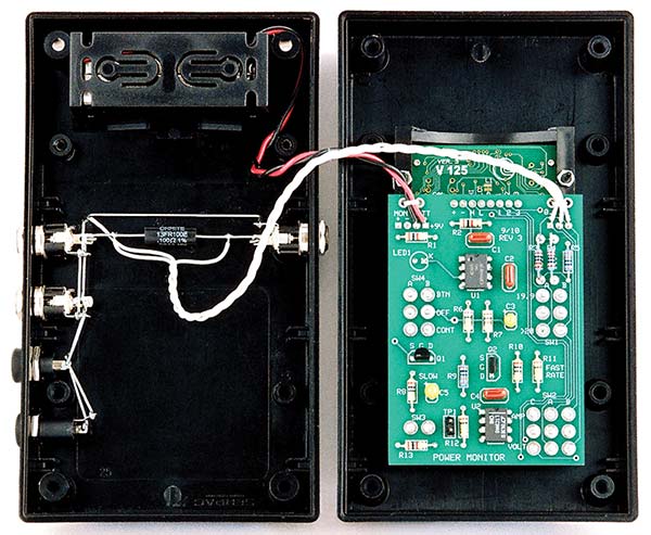
FIGURE 4. Interior view shows battery box, 0.100 ohm current sense resistor, and the PCB.
SPECIAL NOTE: It is important that the wires soldered to the current sense resistor, R14, are connected at a spacing of 1.310”, as per the spec sheet. This assures the accuracy of its value, 0.100 ohms +-1%.
As much as I like the Martel V-Series voltmeters, they have a flaky mounting scheme. Figure 5 is a close-up of the front bezel. It has two plastic mounting posts that accept push-on fasteners. I broke off one of the posts as I struggled to push on the first fastener. It was my fault, but there had to be a better way.
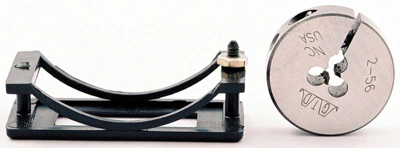
FIGURE 5. Threading die allows the LCD bezel to be secured with 2-56 nuts.
The solution was simple: Buy a 2-56 threading die from McMaster-Carr. The diameter of the posts just happens to be real close to a 2-56 screw. By carefully threading the posts, you can use 2-56 nuts to secure the LCD. Sweet!
Using a digital ohmmeter, I selected the non-standard voltage-divider resistors, R3 and R4, from a pile of 1K and 110 ohm resistors. Then, I soldered them on the PCB, along with all the other components and the LCD connector. R1 was only used during development so it may be omitted.
Testing
Next, I plugged the unmounted LCD into the PCB and did a thorough electrical check of every function, using clip leads to simulate the switches. When I was confident that everything was working, I mounted the LCD in the case, soldered the PCB to the switches, and connected the wires from the battery and sense resistor.
Finally, I briefly shorted TP1 to test the low battery 5 Hz fast rate, then closed the case and put in the four screws. Done at last. Eagerly, I plugged a wall wart into the appropriate input jack and the output plug into a Parallax BOE Board. It read 7.66 volts at 88 milliamps. Success!
Final Word
I’ve been using the Wall Wart Power Monitor for some time now, and it works great. It’s been a fun and useful project for me. I think you’ll find it useful too.
For the Next Model
If the input and output connectors were changed to the board-edge mounted type, then all the connectors and the 0.100 ohm resistor could be mounted on the PCB, making a cleaner design.
Here’s an outside-of-the-box idea. How about using solar power from the room lights to supply the 1 mA for the LCD? NV
PARTS LIST
| ITEM |
DESCRIPTION |
DIGI-KEY |
| C1, C2, C4 |
0.1 µF, 50V, Bypass |
P4525-ND |
| C3 |
2.2 µF, 20V, Tant |
478-1869-ND |
| C5 |
10 µF, 20V, Tant |
478-1840-ND |
| 1% RESIS |
Metal Film, 1%, 1/4W |
value+XBK-ND |
| OTHER RES |
Carbon Film, 5%, 1/4W |
value+QBK-ND |
| R14 |
0.100 ohms, 1%, 3W |
13FR100E-ND |
| Q1 |
2N7000, N-chan MOSFET |
2N7000FS-ND |
| Q2 |
ZVP2106A, P-chan MOSFET |
ZVP2106A-ND |
| U1 |
LMC555 Timer |
LMC555CN-ND |
| U2 |
LTC1440 Comparator |
LTC1440CN8#PBF-ND |
| SW1 |
DPDT, Toggle |
EG2400-ND |
| SW2 |
3PDT, Toggle |
EG2425-ND |
| SW3 |
SPST Pushbutton, N.O. |
Mouser, 10PA322 |
| SW4 |
DPDT, Center-Off, Toggle |
EG2414-ND |
| J1, J5 |
2.1 x 5.5 mm Panel Jack |
SC1049-ND |
| J2 |
2.5 x 5.5 mm Panel Jack |
SC1048-ND |
| J3 |
1.3 x 3.4 mm Panel Jack |
Mouser, 163-4015-EX |
| J4 |
3.5 mm Panel Jack |
Mouser, 161-1640-EX |
| J6 |
8 pos LCD Socket, 0.1" |
S4108-ND |
| J7 |
9V Battery Connector |
Mouser, 121-1026T-GR |
| P1(4), P2 |
2.1 x 5.5 mm Plug (5) |
SC1052-ND |
| P3 |
2.5 x 5.5 mm Plug |
SC1051-ND |
| P4 |
1.3 x 3.5 mm Plug |
CP3-1003-ND |
| P5 |
3.5 mm Plug |
CP3-1005-ND |
| LCD1 |
LCD Voltmeter, 0.5"digits |
227-1060-ND |
| LED1 |
LED, Red |
67-1066-ND |
| PCB |
PCB w/Mask & Silkscreen |
ExpressPCB |
| BOX |
Serpac, w/Batt Box, Black |
SR251B-ND |
| LETTERS |
White Ltrs&Nums, 4 sizes |
FLS Discount #681012 |
References
www.martelmeters.com/pdf/V_125.pdf
www1.duracell.com/oem/Pdf/Mn1604.pdf
www.ohmite.com/catalog/pdf/10_series.pdf
Downloads
WallWart Power Monitor Download
What’s in the download?
Express PCB file
Case layout and drilling template