For several years, I have used my desktop PC as a DVR (digital video recorder). My current setup uses a Hauppauge WinTV-HVR-950Q about the size of a Flash drive that connects to the PC via USB. The other end of the 950Q is a standard cable F connector. The 950Q has its own internal tuner and the software associated with it allows the scheduling of multiple recordings on different channels (useful if you’ll be away from home for a few days).
This served me well until my local cable company switched to all digital distribution. This means that a cable box is now required for many TVs — even flat-panel HD models that are just a few years old. The problem is that — as far as my 950Q device is concerned — everything is now on channel 4. All tuning is done on the external cable box. This is similar to the way a TV viewing cable through a VCR would remain fixed on channel 3 or 4, and different programs would be selected through the VCR’s remote control.
There are some TV capture cards that include a small IR transmitter that will fix this problem. The capture card will then act like a universal remote, allowing you to change the “real” channel when scheduling a recording, even though the card itself remains tuned to channel 4. Unfortunately, the tiny 950Q does not have this capability.
Recently, when preparing for an overnight trip, I realized that I’d like to record two programs on two different channels. It occurred to me that this might be a job for an Arduino. I had the long-term goal of making the Arduino a “smart” universal remote, but I knew I wouldn’t have the time to do it that night. My immediate solution was much simpler.
I went out and bought a $5 universal remote control and removed it from its case. After programming it as directed to work my cable box, I experimented with a couple of alligator clip cables to see what connections had to be made to activate a particular button.
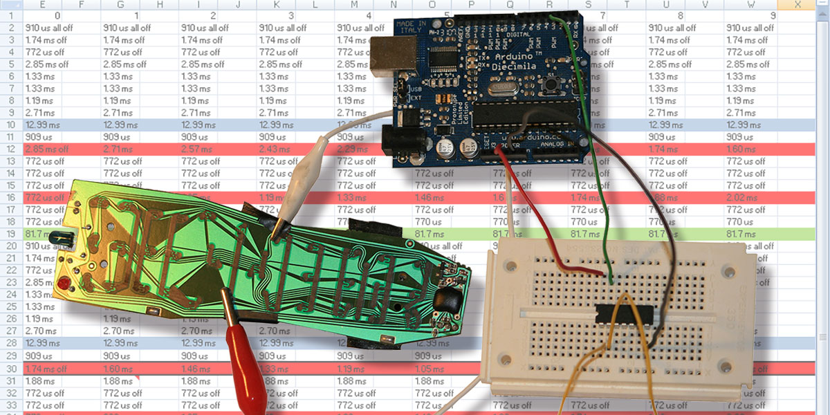
In an effort to just solve the current evening’s problem, I used the remote to go to the two channels of interest, one after another. At that point, all I needed to do was to have the Arduino control the “last” button. Many remotes have this feature that allows you to switch back and forth between two channels by just hitting the same button repeatedly. I used the CD4066B quad bilateral switch IC (less than a dollar) for this. If you haven’t used a switch like this before, it allows you to use a +5V signal to turn a switch on or off. I simply connected the two alligator clips to the two switch ends, and the Arduino to the control pin (Figure 1).
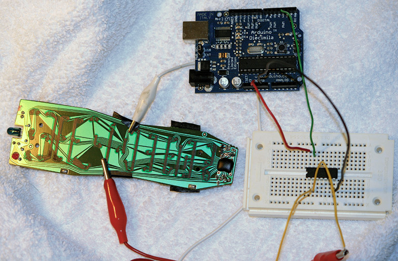
FIGURE 1. Arduino, electronic switch IC, and universal remote control.
The program (Figure 2) to time the switch was incredibly easy.
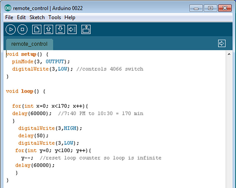
FIGURE 2. Arduino program listing to push a single button on the universal remote.
I wrote a simple loop that does nothing except “delay(60000);” which gives a 60 second delay and runs from 0 to x. When the loop concludes, the Arduino drives the control pin to +5V, holds it there for a short time (50 ms or so), returns it to the low state, and then goes into an infinite loop doing nothing. The recording program (always recording channel 4, of course) would turn on for two hours at 8 PM, turn off, and then turn on for another hour at 11 PM. Sometime between 10 PM and 11 PM, the Arduino has to change the channel. In the program listing, you can see that I was leaving at 7:40 PM and started the program with a value of 170 for the delay variable x. The Arduino was then supposed to change channels for me at 10:30 PM in preparation for the 11 PM recording.
Although this worked, I knew it was a simple and not particularly powerful solution. If I ever wanted to record shows on three or more different channels, it would not do the job. My long-term goal was to remove the switch and universal remote carcass (which was somewhat sensitive to the exact placement of the alligator clip leads) from the picture and just use the Arduino itself as a smart remote control. A quick Google search reveals that there are many websites out there with information about IR remote control protocols and libraries to help program the Arduino to use them. There are even sites that will show you how to use an IR receiver to detect the code with the Arduino, instead of the method described here.
I wanted to do this a different way; I wanted to see if I could just decode what the cable remote (Figure 3) was sending and program it into the Arduino on my own, just using the most basic “digitalWrite” HIGH and LOW commands. For this, I decided to use a new toy. The Saleae Logic logic analyzer ($150) was more than enough to meet my needs for this project.
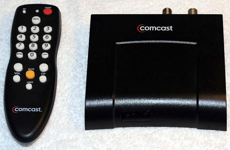
FIGURE 3. The Comcast remote control and digital tuner used in this project.
Figure 4 shows the logic analyzer output of what happens when a “one” is pressed on the remote; at this level of zoom, there are three subgroups of lines visible, each divided into two smaller groups.
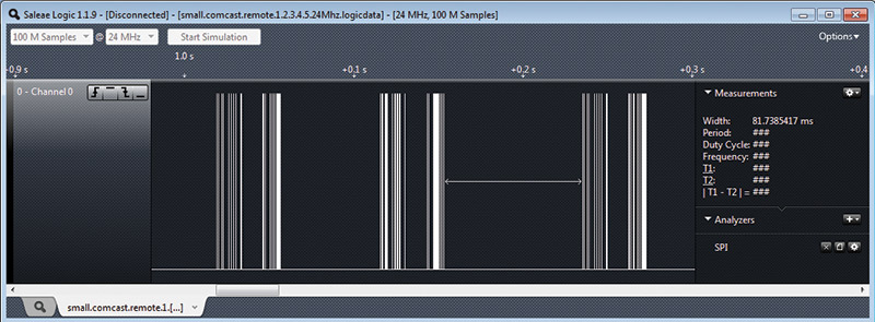
FIGURE 4. The logic output of a "1" from the Comcast remote.
Zooming in on the first half of the first subgroup of lines, we get Figure 5.
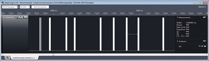
FIGURE 5. The first group of the six sets of lines visible in Figure 4.
We need to go in even closer. Again, zooming in on the first of these nine pulses, we get the picture in Figure 6.
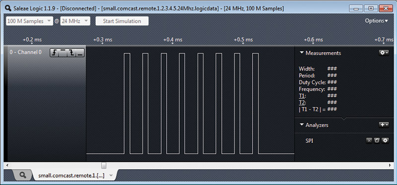
FIGURE 6. Close-up of the first of the nine pulses shown in Figure 5. This is the fundamental pulse sent by the remote every time. Each "fat" line in Figure 5 looks just like this when we examine it closely.
Finally, we can see what is happening. Close inspection of the whole sequence of data sent by pushing a “1” shows that this pattern above is the fundamental word that the IR control understands; delay times between these words provide all of the information the control needs.
When we look at this, we find that the pulse is high for about 8 µs and then off for about 18 µs. I say “about” because the Saleae device can easily show that these pulses have some significant variation. With just the group of eight pulses shown, we have on times from 7.67 µs to 8.29 µs, and off times from 17.79 µs to 18.46 µs. In other words, this is not a case where nanosecond timing is crucial. Note that the on time plus the off time give a period of 26 µs, or a frequency of about 38 kHz — somewhat standard for IR remotes.
After confirming all pulses were really just these eight on/off transitions separated by some time (making this job far easier), it became clear that the useful data was encoded in the delay between pulses. I just had to gather this information for each key (0-9) on the remote that I wanted to emulate. There are 53 delays to measure for each of the 10 digits which sounds like a great deal of work. All you have to do, though, is bump the mouse over from one delay to the next and record that value (provided by the Saleae program) in a spreadsheet. It can easily be done in less than an hour, and you could probably get the timings for all the other keys on the remote (useful if you want to change volume, mute, etc.) in a similar amount of time.
The spreadsheet (Figure 7) made the analysis easy.
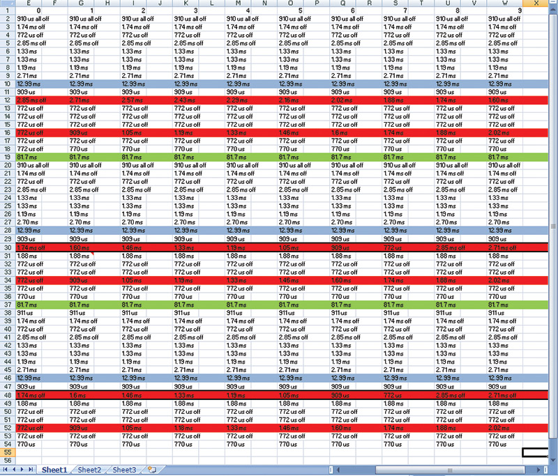
FIGURE 7. Part of the spreadsheet containing inter-pulse delay times for all numbers from 0 through 9.
First, I could see that each button press consisted of three subgroups of pulses, separated by 81.7 µs. While the first subgroup was different from the second for a particular number, the second and third subgroups were identical. By the time I had data for two or three channels, I had figured out that there were only two numbers in each subgroup that changed from channel to channel. Really, instead of gathering 53 * 10 or 530 delays, I would only need six for each digit.
To make analysis easier, I decided to highlight the rows containing the channel-to-channel differences (red), as well as the medium (blue) and long (green) delays. This general process will work for any IR device you can connect to the logic analyzer. Some may use a different encoding — where the delays are not the significant elements — but the principle is the same: Look at what your remote is saying, and then you can program the Arduino to parrot it back on command.
The pattern for channel-to-channel differences was a little harder to spot. If you move across the columns through each red row, you will notice that the delays get either longer or shorter by 140 microseconds from one channel to the next. For example, in row 12 we start out with a delay of 2.85 ms for channel 0, then 2.71 ms for channel 1, 2.57 ms for channel 2, etc. In row 16, our starting delay is 772 µs for channel 0, then 909 µs for channel 1, 1.05 ms for channel 2, etc.
The pattern is reasonably simple, except for the third and fifth set of channel-specific delays (identical to each other; found in rows 30 and 48). In this row, after the numbers have dropped by 140 µs per channel down to 772 µs for channel 7 they jump back up to 2.85 ms and 2.71 ms for channels 8 and 9, respectively. Perhaps delays of 632 µs and 492 µs are too short to be reliable.
Rather than write an algorithm for this, I took the easy way out and just defined a few arrays to hold all of the timing data. The program (Figure 8) begins by preparing a pin (I chose number 10 for no particular reason) for output, setting it low, and waiting for a second. This is because the Arduino kept initially setting the state of the pin high after being declared an output pin, and we need to start with the pin in the low state.
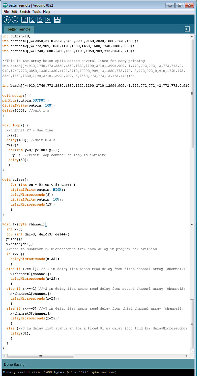
FIGURE 8. Program listing for Arduino as a stand-alone remote control.
The main loop calls the tx (transmit) function once with an argument of 2, waits 0.4 seconds, and calls tx again with an argument of 7. This changes the channel to 27, and the main loop then goes into an infinite wait state. The tx function does all of the real work. It’s just reading in a number from the “batch” array to see how long to wait between calls of the “pulse” function, which is what actually sends the eight high/low signals. The batch array is useful because so much of what has to be sent for a 2 is identical to what has to be sent for a 7 or any other number. These constant numbers are given in the batch array in microseconds.
The only exceptions are for channel-specific data and for the long 81 ms delay, since delayMicroseconds won’t work with a number greater than 16383. If the tx routine encounters a 0, it automatically waits for 81 ms. The other arrays referencing the three possible unique delays for a channel are channel1, channel2, and channel3. If the tx routine encounters a -1, -2, or -3, it reads the correct channel-specific delay from the corresponding array.
Notice that — at the microsecond level — the speed of the Arduino itself becomes important. With just the stated delays, things weren’t working. The pulse function delays to leave the pin high and low are 3 µs and 13 µs rather than 8 µs and 18 µs due to the time spent executing the instructions. The nested if/then/else loop in the tx function takes significantly longer, so the delay times are all reduced by 25 µs. Checking the Arduino’s output with the logic analyzer confirmed that these changes accurately reproduced what the actual remote control was sending.
The hardware side is the easiest part of the whole process (Figure 9). All that is needed is an IR LED (I tried several different ones I had lying around the house — clear, smoky, 3 mm, 5 mm — all worked) with its anode in pin 10 and cathode in ground. Just set the delay loop(s) you need before calling tx.
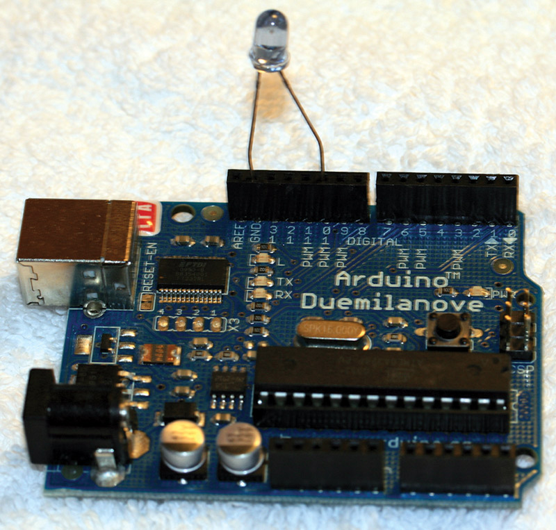
FIGURE 9. The completed Arduino, ready to send instructions to the digital tuner box.
Extensions to this could be interesting. Perhaps the most obvious would be to incorporate something like a DS1307 real time clock so that there would be no need to calculate how many minutes of delay are needed. The day, time, and channel could be programmed directly and the Arduino could just wait for it.
The Arduino itself could be replaced by just the AVR chip (or a suitable PIC or other microcontroller) for a smaller package. A cheap universal remote could provide a ready-made case and means of inputting numbers. Add a small LCD display and you have a truly “smart” remote without a large form factor.
As an intermediate project, notice that while some TVs can be programmed to turn on at a certain time, many can’t. An ordinary outlet-based timer and relay won’t work, since just plugging in a modern TV won’t cause it to turn on. Quick experimentation to find the “power” code from the remote would allow the Arduino to wake you up with your favorite station — even if you went to sleep watching another one. (Much better than a screaming alarm clock!)
If you’re going to be away from home and want to periodically turn on the TV to make the place look like someone’s home, this is one way to do it. This could be extended to other entertainment devices, as well as cameras (those with IR remote controls), ceiling fans, etc. NV