Analog comparators, though not particularly sexy, must surely rate as one of the more useful building blocks for a wide variety of circuits. They can be used to generate pulse width modulation, monitor under- or over-voltages, shape up ugly signals into nice crisp pulse waves, act as logical inverters, help with interfacing mechanical switches, and more. A comparator has two analog inputs and a lone output, which can be considered digital since it can assume only two possible states. If the voltage on what's referred to as the non-inverting input exceeds that on the inverting input, then the output snaps high; otherwise, it remains low.
It’s easy to forget that most PIC microcontrollers sport one or more uncommitted analog comparators. For example, after my article “An Easy Two-Wire LCD” appeared in Nuts & Volts, all of a sudden it hit me (a slap on the forehead moment) that the transistor inverter required there could be completely eliminated — including its two resistors — and replaced with an internal comparator within the driving PIC chip. Just like that, the parts count shrinks by three components, and at no extra cost.
Apart from forgetting to make good use of these comparators, there’s that business of the datasheet. On the one hand, I’m delighted Microchip (the manufacturer of PICs) has given us such comprehensive materials to work with. Yet, who hasn’t dragged their feet when first approaching this huge daunting manual?
That’s where this article comes in. Besides reminding you of the utility of comparators, it will reorganize the concepts of the datasheets into something more approachable. We’ll get the big picture in mind first, and only after that will we proceed to the details.
Along the way, seven experiments give you a chance to really nail everything down; these are the very tests I performed to confirm what was going on. With just a handful of common components at your side and a couple sessions at the breadboard, you’ll be all set to design your own PIC circuits exploiting analog comparators.
The Big View
As mentioned, just about all of the PIC chips contain at least one analog comparator available for use in various modes or configurations. To keep things specific here, let’s consider the ever-popular PIC16F88 — one of the most commonly employed microcontrollers. Do keep in mind that similar arrangements are apt to apply to whichever specific PIC chip you’re keen on.
There are so many options available that it’s easy for your eyes to just glaze over and make you want to walk away from the mess. In my 30 years of teaching, I’ve always found branching tree diagrams useful for organizing multiple options. Somehow, visualizing the choices graphically makes them all less daunting, and the details won’t swamp you.
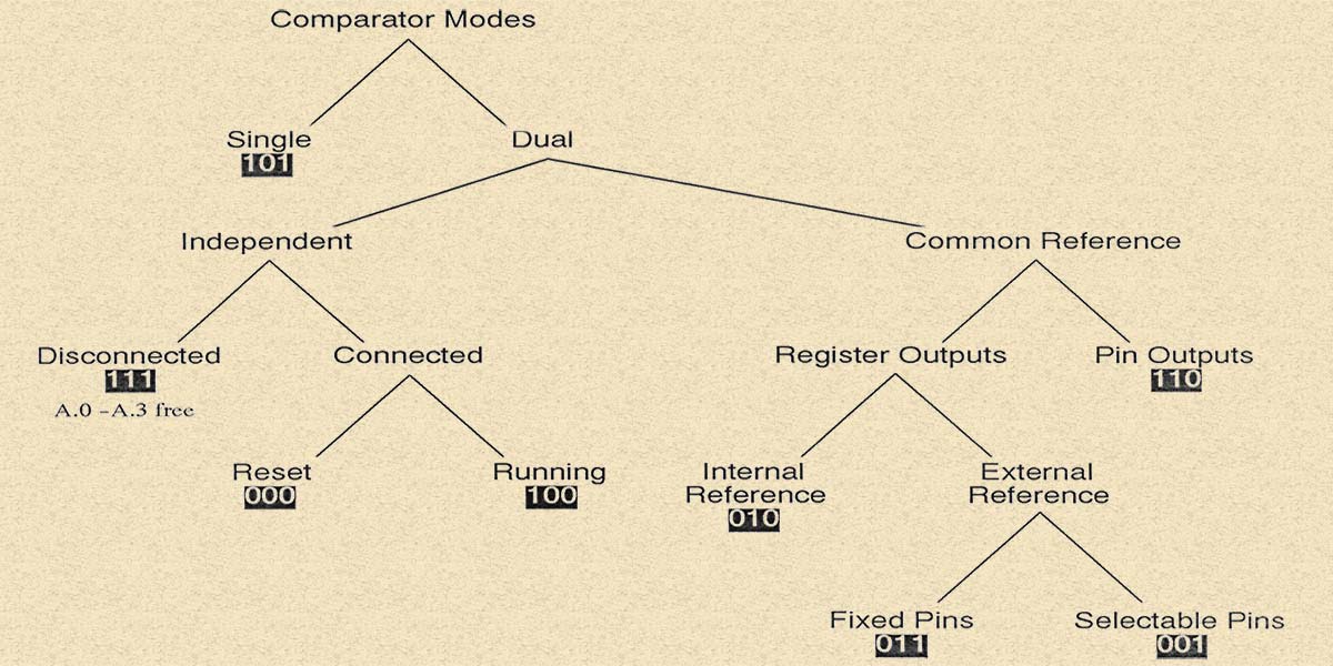
Let’s begin by referring to Figure 1 which illustrates the relationships among the eight possible modes available for the two comparators within the PIC16F88. Each mode is indicated by a three-bit binary number (more on this later).
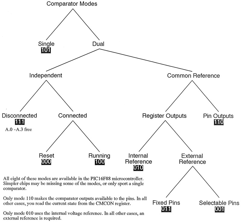
FIGURE 1.
The figure really does tell most of the story quite well, so I won’t waste many words here describing what you can see for yourself. Let me just point out a few of the more salient particulars.
Starting at the top of the diagram, you’ll see that the comparator modes split into two main categories: Single and Dual. In Single mode, only comparator 2 is enabled. Comparator 1 is completely disconnected from the PIC (via internal multiplexing), freeing up its associated pins for other uses.
On the other hand, with any of the Dual modes, both comparators are available. The Dual modes can be divided into two major categories: Independent and Common Reference. As the name implies, in an Independent mode the two comparators are completely divorced from one another and can be treated as separate circuits. A Common Reference mode has the two non-inverting inputs ganged together. Typically, this frees up a pin for other applications in the PIC.
Continuing our tour of the tree, Independent mode splits in two again — either Disconnected or Connected. If the comparators are disconnected, they are indeed disabled altogether, and their pins (port pins A.0 through A.3) are liberated for other general-purpose uses. This is the default situation at power-up, which is why many of us forget about the comparators!
If the comparators are, in fact, connected, then the internal multiplexer brings the inputs out to the chip pins. As Figure 1 indicates, there are two Connected modes: Reset and Running. When the mode is configured to Reset, the comparators are still hooked up, but their outputs are forced to be zero regardless of the state of the inputs. Otherwise, in Running mode they are free to operate independently of whatever else the microcontroller is up to.
That takes care of all the Independent modes. Move over to the Common Reference modes mentioned earlier. You get two main choices here: Register Outputs or Pin Outputs. In the former, the outputs of the comparators are only accessible from within an internal register (CMCON) to be described in a moment. In the latter, it is also possible to route the outputs to physical pins on the PIC16F88, in which case the comparators behave like any outboard unit you may have used in the past.
Now, the Register Output modes bifurcate, giving the ability to sense either an Internal Reference or an External Reference. In either case, the reference voltage will be applied to the non-inverting inputs of the comparators.
Finally, when using an External Reference, you get a choice of either the default pins that Microchip has designated, or are offered some flexibility on which ones actually connect up to the inverting inputs. That’s thanks to the magic of multiplexing. This would make it possible to choose one of two voltages to monitor under software control; for example, sort of like an SPDT switch.
How to Select a Mode
Setting each of these eight modes is a snap by means of the CMCON register. The acronym stands for Comparator Module Control, of course. This is illustrated in Figure 2.
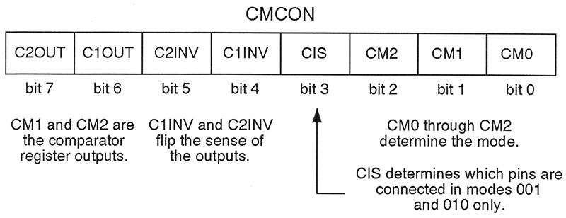
FIGURE 2.
Take a look at bits 6 and 7 first. These are the comparator output bits alluded to previously. They are always in operation, diligently following whatever the two comparators are up to. Clearly, they are read-only in nature.
Bits 0 through 2 form the three-bit mode number mentioned above. Did you notice these codes in Figure 1? Just pop the desired number in here and away you go.
Bit 3 is only required by modes 001 and 010, and lets you select which pins actually connect to the PIC comparators. You’ll get a chance to see it used in the experiments.
Finally, bits 4 and 5 provide a nice little piece of flexibility. These guys change the sense of the comparators under software control. For example, if bit 4 is cleared to zero, then comparator 1 behaves as you’d normally expect. Make it a one, and then it becomes an inverting comparator.
This is sort of like exchanging the inverting and non-inverting inputs, and is particularly useful in keeping the firmware less convoluted to the eye.
What About Interrupts?
Designing circuits and software to handle an interrupt generated by the comparators is remarkably straightforward. Here are the few things you need to know.
There are three levels of interrupt enable flags (sometimes called masks in other processors). At the deepest level, you need to set the flag CMIE (which stands for Comparator Module Interrupt Enable) when you do indeed want interrupt action.
You’ll find this in the register PIE2 — an acronym for Peripheral Interrupt Enable 2. Obviously, the comparators are considered to be peripherals.
One step up from this is the PEIE bit, or the Peripheral Interrupt Enable. It too must be set to get things cooking. Look for it in the register named INTCON — a symbol for Interrupt Control.
Finally, at the highest level, you’ll need to set the flag GIE, which is an abbreviation for Global Interrupt Enable. This one is also found within INTCON.
Putting it all together, if you really do want the comparators to generate interrupts, then set CMIE, PEIE, and GIE. If any one of these is clear, then the interrupts are masked.
One final thing. If you look inside register PIR2 (Peripheral Interrupt Register 2), you’ll notice the bit CMIF, which stands for Comparator Module Interrupt Flag. This bit is constantly watching the comparators and is set any time a state changes — regardless if the interrupts are masked or not. When you enter a comparator interrupt routine, be sure to clear this flag before returning to the main program.
Don’t be disheartened if it sounds a bit messy! As you’ll see in Experiment #7, it’s remarkably easy to make this stuff all work.
Experiment #1
Let’s stop all this yammering and head straight to the workbench! Your first step is to visit the article link and get the firmware source code. The programs have been created with the excellent and free open source compiler, Great Cow Basic which I’ve mentioned often in previous articles.
The syntax is exceedingly similar to PICBASIC PRO should that be your weapon of choice. Heck, even porting it over to C shouldn’t be all that onerous, since I’ve annotated and commented the source code like crazy.
Check out Figure 3. In Experiment #1, we get to see mode 101 in operation. Recall that only comparator 2 is utilized, with the other being disabled. A reference voltage of +2.5V (courtesy of divider R2/R3) is applied to the inverting input (at pin 18) as the reference.
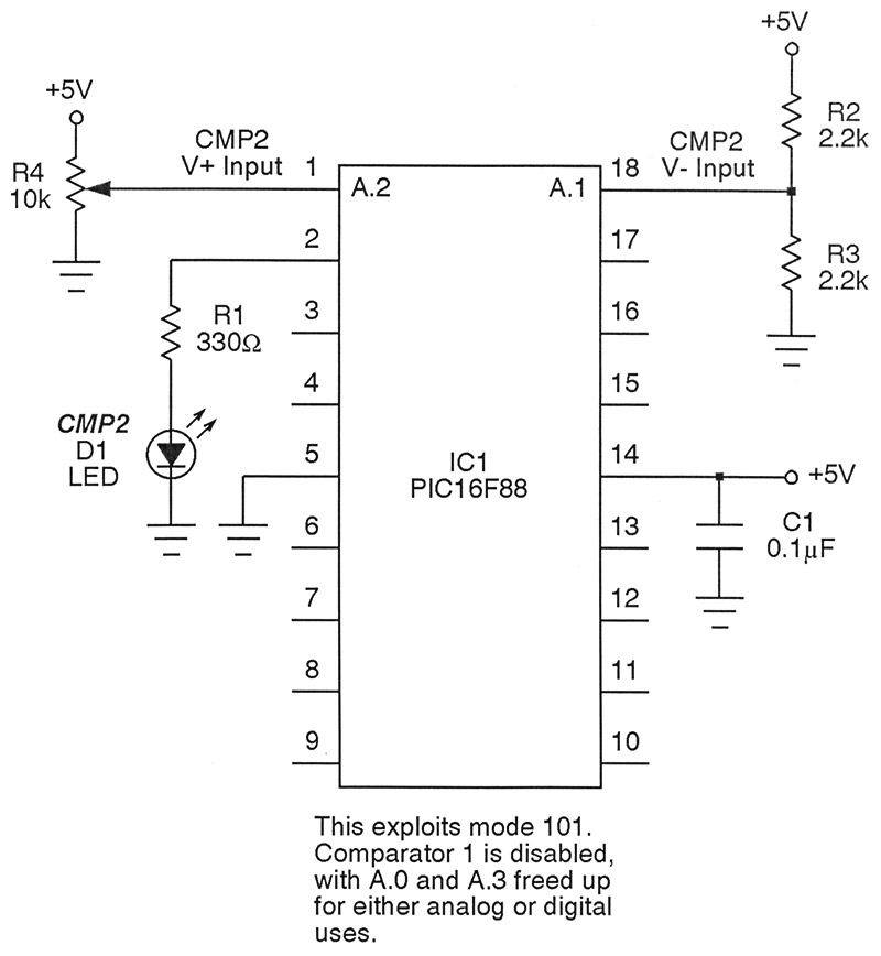
FIGURE 3.
Now, while monitoring the wiper of potentiometer R4 with a multimeter, watch what happens as you increase the voltage on the non-inverting input at pin 1. Once it exceeds +2.5V, LED D1 snaps to attention.
Observe that since comparator 1 is out of the picture, port pins A.0 and A.3 are freed up for any other use you have in mind. This is a simple experiment, but a great way to get your feet wet.
Experiment #2
Now, turn to Figure 4 which shows the layout for the next experiment.
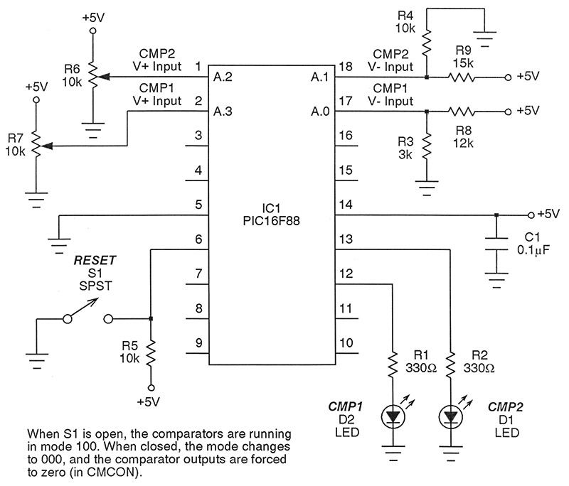
FIGURE 4.
We’re in Dual mode now, with both comparators doing their thing. In particular, you’ll get to see them running normally or have their outputs forced to reset.
A +1V reference is applied to comparator 1 at pin 17, while +2V is put onto comparator 2 at pin 18. Again, while monitoring the wiper of either R6 or R7 with a multimeter, observe how LEDs D1 and D2 respond once the threshold voltages are reached.
Closing switch S1 puts the mode to 000, which forces both comparators to reset — regardless of what the potentiometers are up to.
Experiments #3, #4, and #5
The next three experiments use the schematic in Figure 5.
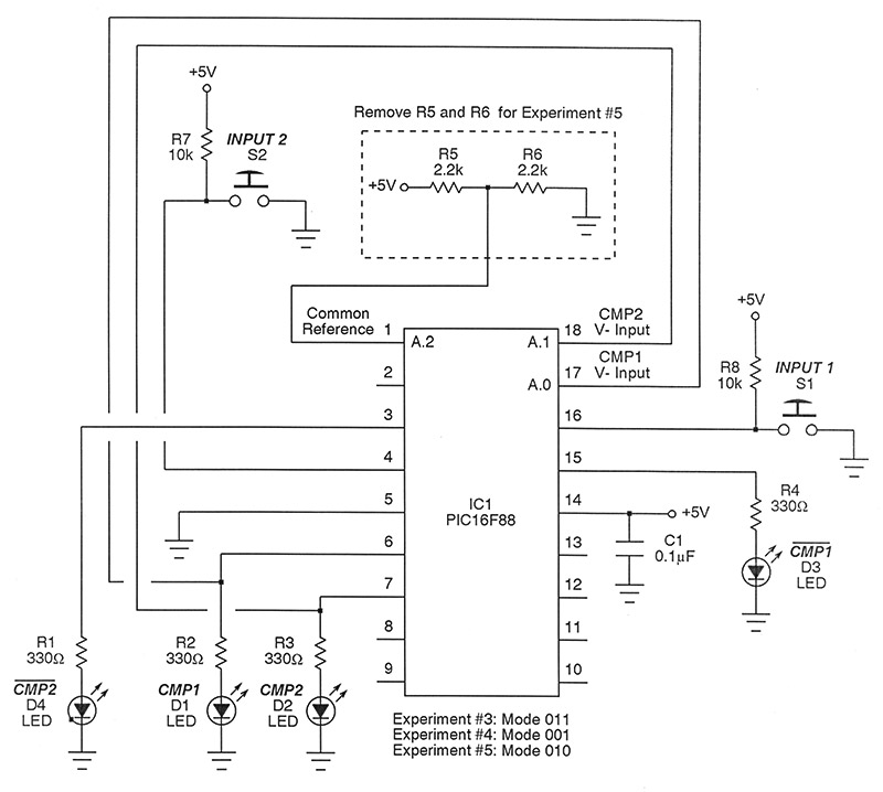
FIGURE 5.
In all cases, the comparators are instructed to behave as inverters, but now we’ll let the non-inverting inputs be the reference. For example, LEDs D1 and D3 will light oppositely from one another, since comparator 1 is acting as an inverter now. Pressing pushbutton switch S1 will toggle these back and forth. S2 behaves similarly with the second comparator. If you want more details, they’re in the source code. In Experiment #3, mode 011 is used which gives a fixed pin arrangement and an external reference (provided by divider R5/R6) applied to the ganged reference inputs of the comparators.
Mode 001 is utilized in Experiment #4. This implies that reference pins 17 and 18 could be assigned elsewhere if desired. Again, multiplexing makes this all possible.
For Experiment #5, completely remove voltage divider resistors R5 and R6 because an internal reference of +2.5V will be handily created by the PIC. Refer to the source code to see how easy it is to generate the desired voltage. If it isn’t clear, we’re using mode 010 now.
Experiment #6
You’ll find the circuit diagram for this experiment in Figure 6.
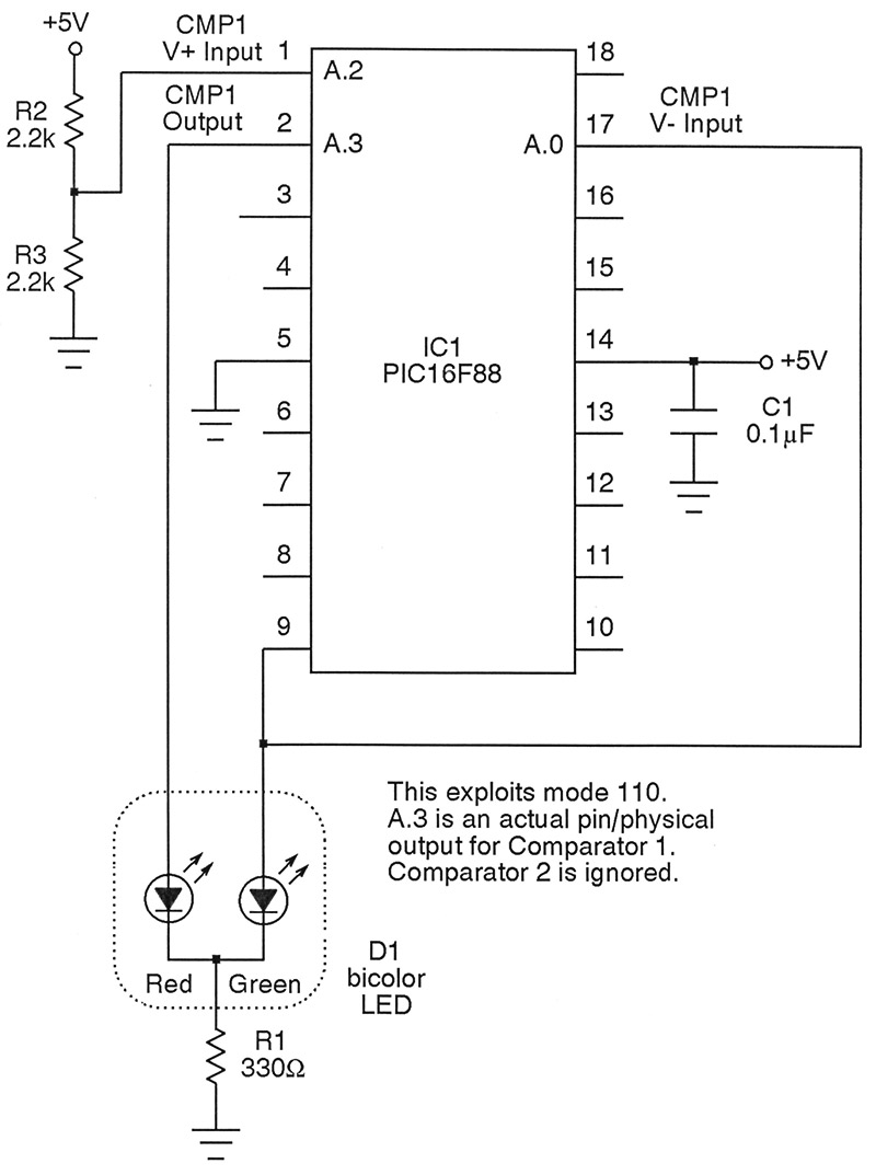
FIGURE 6.
At last, we’re using the pin output feature provided by mode 110. In particular, the pulse width modulation unit within the PIC16F88 applies a varying rectangular pulse to the green element within bicolor LED D1. Simultaneously, that signal is pumped through comparator 1 acting as a logical inverter. Its output is then applied to the red element of D1.
This implies, for example, that when the green element is seeing a 75% duty cycle signal, the red element is getting a 25% signal. The program sweeps these back and forth, giving a pleasing morph of green to orange to red and back again, over and over.
Experiment #7
This is a neat little demonstration, and really shows off the power of Great Cow Basic simultaneously. Figure 7 shows the schematic.
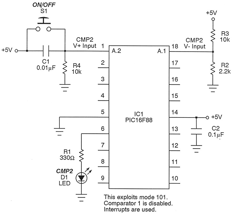
FIGURE 7.
In this case, we’re using interrupts and coercing the PIC to behave as a sort of retriggerable one-shot. Press pushbutton S1 briefly, and LED D1 will light for one second. Press and hold the switch, and the LED simply stays lit until the button is released.
Utilizing comparator interrupts is particularly easy, as the source code readily shows. Give it a quick read-over and see for yourself.
Some Lessons Learned
When I first timidly approached the PIC datasheet, I fell into the trap of misinterpreting a number of concepts concerning the analog comparators. Then, there was the swirl of too many details thrown at me all at once. After working the experiments, I found that everything behaved very simply after all, and reliably to boot. Let me relate just a few of the things I picked up along the way; maybe they’ll save you some headaches.
- The comparators are disabled by default at power-up.
- There is no need to diddle at all with ANSEL, the analog select register. Setting the mode in CMCON takes care of configuring the input pins as analog.
- Do set the data direction in TRISA for the input pins.
- Any pins not actively used by the comparators are available for any other purpose.
- The comparator inputs always read as zero (not that you’d want to read them directly anyway).
- The output impedance of whatever is driving the comparator inputs should be less than 10K.
- Altering a mode midstream in a program may fire an interrupt.
- Any change in either comparator (low to high or high to low) triggers an interrupt.
When I first looked into the PIC comparators, I think I probably scared myself based on what I was seeing in the datasheet. However, I hope you agree now that, in fact, they’re a breeze to work with.
Run the experiments and prove it to yourself! NV