The CSS555 is a micropower programmable version of the 555 family of timer ICs. It operates at a current under 5 µA and a supply voltage from 5.5V down to 1.2V. These qualities make it particularly well-suited for long lasting battery and small solar powered projects.
Standard 555 Micropower Operation
The CSS555 is pin-for-pin compatible with the customary 555 series timers as Figure 1 indicates.
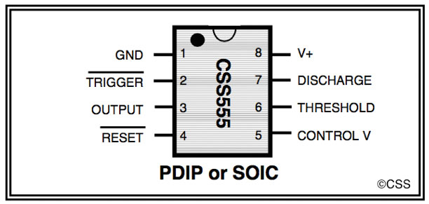
FIGURE 1. The CSS555 has the same pinout.
Therefore, application circuits have the familiar 555 topology as, for example, in the astable circuit illustrated in Figure 2.
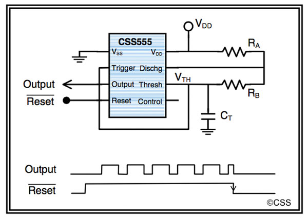
FIGURE 2. Astable circuit diagram. Note that the reset pin must be held high for the chip to be active.
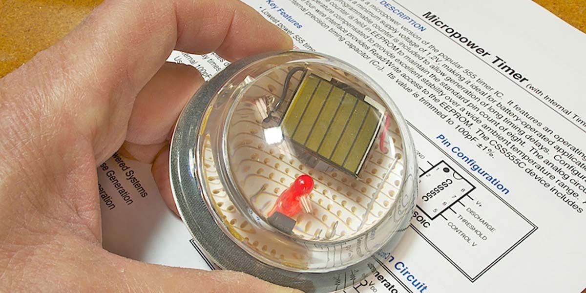
However, the micropower nature of this IC allows using external components with values that demand much less power. For example, the LED blinker in the electronic paperweight in Figure 3 uses the above astable circuit with timing resistors RA = 10M, RB = 47K, and a 0.22 µF timing capacitor. It blinks perpetually on the energy stored in a 1F capacitor charged from a small photovoltaic cell taking in typical desktop lighting.
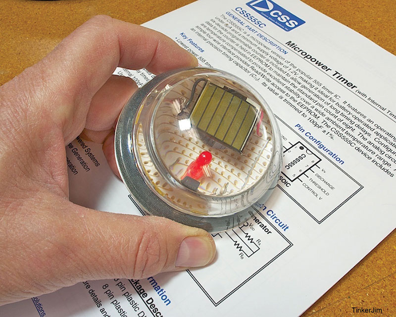
FIGURE 3. This electronic paperweight holds down papers by automatically utilizing the ambient gravity field. It also blinks.
Another application of the CSS555 in the standard (unprogrammed) mode is the solar engine shown in Figure 4. Here, the circuit is a sort of monostable arrangement with a more or less constant voltage (about 1.4V usually) on the trigger and threshold pins, which is supplied by a photodiode (a suitable LED, actually). The supply voltage to the circuit varies as the storage capacitor Cs charge from a solar cell, or discharge through the load when the output pin goes high.
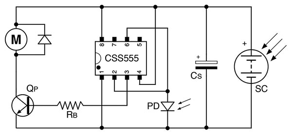
FIGURE 4. The CSS555 as the heart of a very efficient solar engine circuit.
It goes high when the supply reaches three times the trigger voltage, and goes low when the supply drops to 1.5 times the photodiode voltage.
The original concept for this solar engine circuit was devised by Manfred Schaffran and Wilf Rigter in 2003 when only the 7555 timer was available. The CSS555 greatly improves the efficiency since the circuit now takes under 5 µA during periods when the storage capacitor is charging up. The various available 7555s required anywhere from 50 µA to 180 µA. A CSS555 equipped solar engine has operated perfectly from a tiny solar cell supplying a mere 15 µA.
The little robot “Walker” in Figure 5 is equipped with this circuit, a good size solar cell atop his head, and, presently, a 0.22F capacitor. He periodically waddles around in a little circle (one of his arms/legs is longer than the other) whenever he has gleaned enough energy from the surrounding light. More information on all these projects can be found at Instructables.com. The ultra low power feature of the CSS555 truly excels in projects such as these.
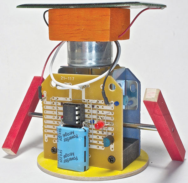
FIGURE 5. “Walker the Robot.” He is energized by the solar cell on his head.
Extended Mode Operation
The second remarkable feature of the CSS555 is that it is user programmable for extremely long timing periods — from hours to days — with small value capacitors. The chip includes an internal counter that tracks the capacitor charge/discharge cycles and changes the output pin state when the selected number of cycles has occurred. Figure 6 illustrates this with a counter value of 10.
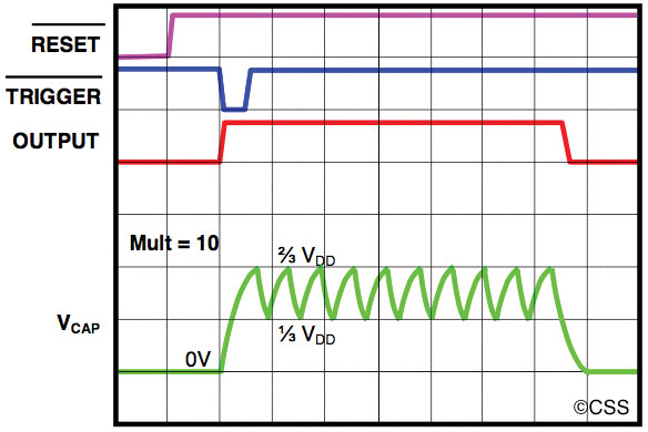
FIGURE 6. Waveforms of the CSS555 running as a monostable in extended mode with its counter set to 10.
Selectable counter values go in multiples of 10: from 100 = 1 (the standard 555 mode) up to 106 = 1M. Figure 7 illustrates a monostable circuit set up for a delay of about 16 minutes using a capacitor of only 100 pF (which is built into the CSS555C variety of the chip).
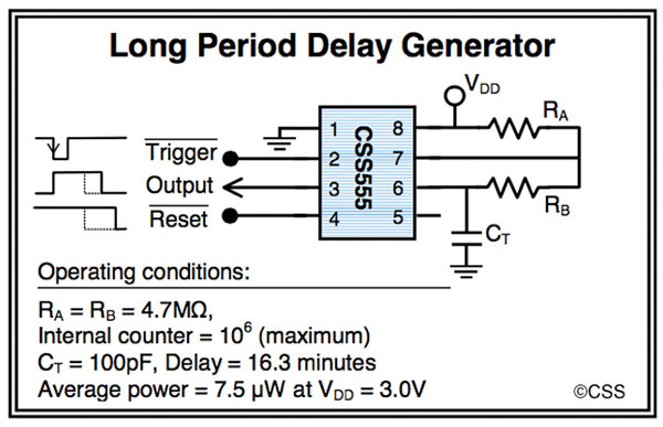
FIGURE 7. One-shot circuit using extended mode, giving an on time of 16.3 minutes.
For the extended functions, access to a programming board is needed, of which two are available from Custom Silicon Solutions (CSS; www.customsiliconsolutions.com). The “EZ Programmer” shown in Figure 8 works from two AAA cells, reads the current settings on the chip, shows them via LEDs, and will reprogram the chip according to the positions selected for the switches. It is extremely easy to work with this programmer.
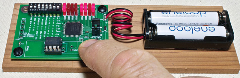
FIGURE 8. “EZ Programmer” from Custom Silicon Solutions.
The other programmer (a deluxe version) is supplied in the CSS555C Demonstration Kit. It works through a computer via USB and the configuration settings can be selected from drop boxes. The screenshot of this programming package in use shown in Figure 9 shows many of the options that are selectable for this timer.
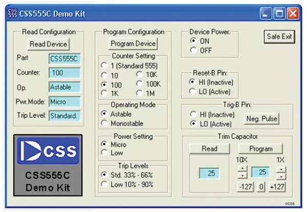
FIGURE 9. Screenshot of the computer-based CSS555 programmer.
A Practical Application
The following project illustrates a very practical application of the CSS555 operating in the extended mode. The 5” battery powered fan in Figure 10 proved itself well worth the few dollars it cost. Whenever conditions got a bit warm, I used it on the desk or next to the easy chair when just a little quiet breeze was all that was needed to maintain comfort. It was indeed quiet — especially on the low setting — which seemed to be the most used.
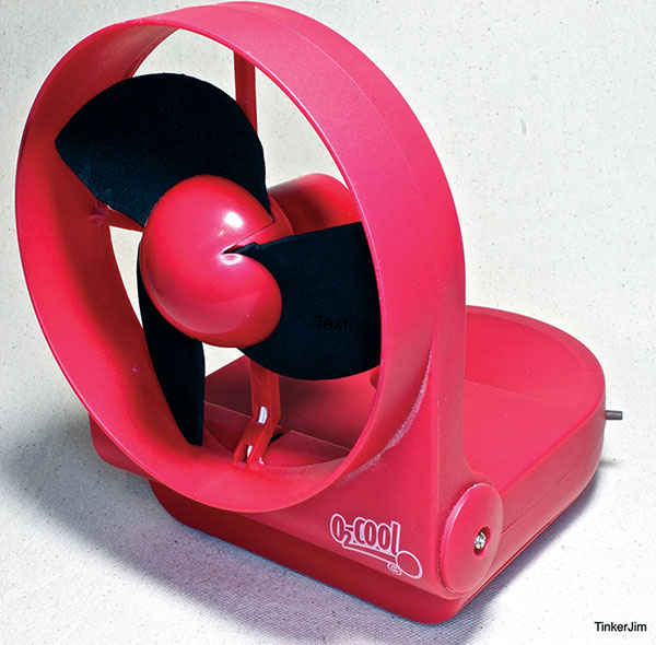
FIGURE 10. The “O2Cool” personal fan powered by two D cell batteries.
This fan was so quiet, in fact, that more often than not, I would altogether forget the thing was on and fail to turn it off. When I’d return to the scene and reach to turn it on, I would find to my dismay that it was already on, but with two dead D cells! Reminder notes placed in various locations proved futile.
After a couple of summers of this, it finally dawned on me that the CSS555 in extended monostable mode offered a nice solution to this problem — and a significant savings in D cell batteries! It could be configured to run for around 15 minutes after just a touch of a button. During idle periods, it would consume a negligible level of power, taking less than a half dozen microamps between button pushes. Of course, a microcontroller first came to mind but experience with this fan showed that it could provide adequate comfort when its series-connected pair of batteries wore down considerably below 1.5V. This was well below the brownout voltage for the micros on hand. With the EZ Programmer, the CSS555 could be set for “low voltage” operation, which allows it to function from 1.2V.
Also at this setting, the timer trip levels of the IC are set farther apart: 10% and 90% of the supply voltage, instead of the usual 1/3 and 2/3. This lengthens the delay time (i.e., output pin high) by about 3X to:
(Counter)•(2.197)•(RA + 2•RB)•CT
Figure 11 shows the schematic used for the fan circuit. With a counter setting of 104, RA = 3.3M = RB, and CT = 4.7 nF, this circuit gives a measured on time of some 17 minutes, which works out just fine. When the fan turns off (which in itself is very satisfying to one who has gone through so many D cells due to forgetfulness!), if it starts feeling a bit warmish, just another touch of the button restores comfort. When leaving the scene when the fan is still going, it could be turned off via the built-in Off-Low-High slide switch. I usually just let it go, knowing that it will turn itself off in a few minutes and then be standing by ready to go with a tap on the button tomorrow or next week — or whenever it is needed — with its batteries in essentially the same condition.
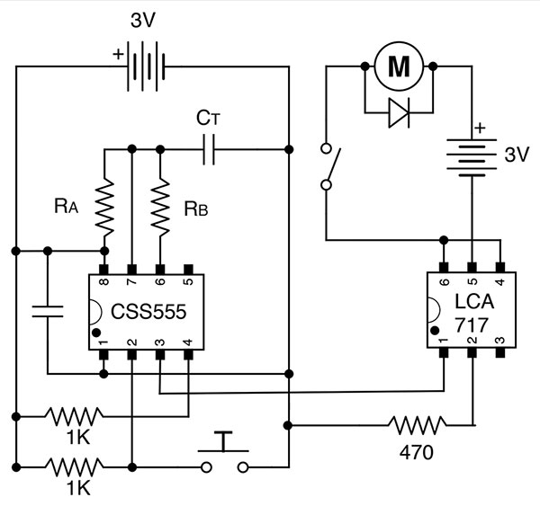
FIGURE 11. Schematic of the one-shot circuit used for controlling the fan motor. Note the bypass capacitor across the supply and ground; 0.1 µF suffices in such applications.
A simple MOSFET to control the motor was ruled out since (as mentioned above) it was desired to have operation when the supply gets below 1.5V. This would not have met the gate threshold voltage for the MOSFET on hand. However, I had several LCA717 OptMos chips in my parts box. The LCA717 is an excellent device for motor switching applications. It requires only 1.2V forward to turn on the load, and has very low on resistance. The LED within needs 2 mA which is negligible relative to the current draw of the motor, which in the fan ranges from about 180 mA on low to 350 mA on high (with new batteries).
The LCA717 has the advantage (for some applications) of using a separate power source for the load, which is the way the circuit schematic here is shown. In this fan application, both the timer and the load share the same two series-connected D cell batteries. Figure 12 shows the completed circuit board, which was easy to fit in the cavity of the fan base.
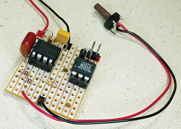
FIGURE 12. Circuit board of the now battery-saving fan.
Conclusion
I hope this short article will serve as an indication of the capabilities of this timer. The documents that CSS has prepared for these chips give much more information. They are very thorough, easy to follow, and have plenty of illustrations — some of which have been presented here (with permission of course!). The information sheets available for downloading from the CSS website include SPICE models, timer delay and adjustable duty cycle calculators, and a collection of application circuits showing the many ways this remarkable timer can be put to work. NV