A casual observer might think that wireless systems consist primarily of filters connected by the occasional bit of circuit! Block diagrams of transceivers often include as many filters as any other function. This is true at the system level, just as it is at the circuit level — and many circuits behave in a filter-like way, whether intended to be a filter or not! That makes understanding filter basics important for wireless success.
What is a Filter?
Looking up “filter” generates a lot of entries! Along with the electrical definitions, there are adaptive filters and image filters and so forth, as well. The general idea, though, is to operate on an input signal (or data) so that the output is modified based on some pre-defined quality of the input signal. With respect to electrical signals, a filter is a circuit or function with an effect that varies with the input signal’s frequency, wavelength, or phase. All three of those characteristics are basically the same thing: a regular variation in time.
Analog and Digital Filters
As with just about everything else in ham radio, filters can be analog or digital. The common passive (unpowered) analog filter consists of familiar inductor-capacitor (LC) or resistor-capacitor (RC) circuits. If some kind of amplifier is used, the circuit becomes an active filter. Most active filters use op-amps in a variety of feedback circuits. Figure 1 shows an example of each type of filter circuit.
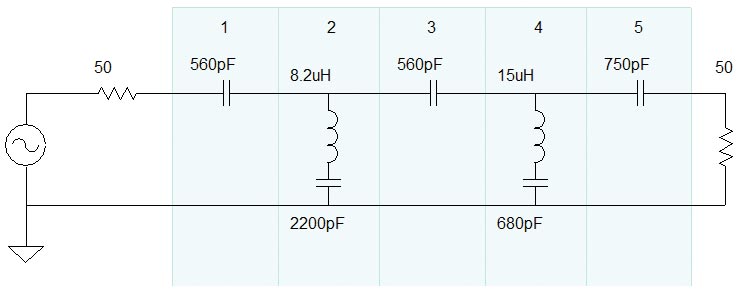
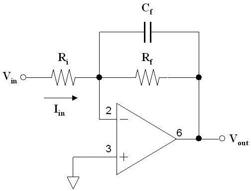
FIGURE 1. Filter A (top) is a passive high-pass LC filter used for rejecting AM broadcast band signals. Filter B (bottom) is an active low-pass op-amp filter typically used for audio signals.
A digital filter requires analog signals to be digitized, creating a stream of digital data representing the original signal. Once digitized, any mathematical operation can be performed on the data. If the result is to be viewed or listened to by a human, the digital data is converted back to an analog signal. Processing and converter electronics are now inexpensive enough to implement that digital filters (and many other signal-processing functions) are taking over from analog in ham radio. This article will stick with the traditional analog circuits, but the general definitions and specifications for how the filter behaves apply to all filters.
Common Filter Types
Nearly all electrical filters (assume we are talking about electrical filters from this point on) are described and specified by their effect on the amplitude or magnitude of signals having different frequencies. (The phase response is also important in many applications.) This is the filter’s frequency response and because it describes signal amplitude, it is a magnitude response. Several types of responses are shown in Figure 2. Filters also have a phase response that describes the phase relationship between the input and output signals. (There is also a time-domain response such as you would see on an oscilloscope screen.)

FIGURE 2. Four different types of filter responses: low-pass (A); high-pass (B); band-pass (C); and notch or band-stop (D). (Figure courtesy of the American Radio Relay League.)
Figures 2A and 2B show the high-pass and low-pass responses. Figure 2C is a band-pass response and Figure 2D is a band-stop or notch response. Each response has a pass-band (where signals aren’t attenuated) and a stop-band where signals are rejected. All have many uses in radio, mostly in attenuating unwanted signals. We’ll discuss some of these uses later in the article.
Filter Specifications
Before using or selecting filters, you’ll have to know how they are specified. Beyond just the broad high- or low-pass type, you’ll have to be able to give specific frequencies and specific levels of attenuation. Each of these parameters has a name and precise definition. Figure 3 shows a high-pass filter’s magnitude response.
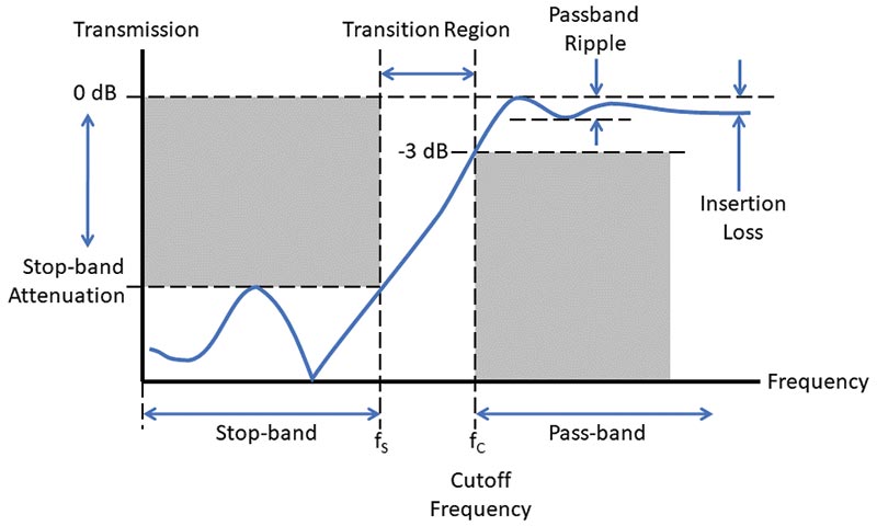
FIGURE 3. A filter’s key specifications for its amplitude response. The gray boxes establish the basic performance (see text).
Drawing the gray boxes on a response graph establishes the filter’s basic behavior.
- Cutoff Frequency: The frequency, ƒC, at which the output signal has one-half the power of the input signal. This is useful in specifying where the pass-band ends and where the stop-band begins. The cutoff frequency is also referred to as the –3 dB frequency because –3 dB is equivalent to a power ratio of one half.
- Bandwidth: If a filter passes or rejects only a range of frequencies acting like both a high-pass and a low-pass filter, there will be two cutoff frequencies. The higher one is ƒH and the lower is ƒL. In Figure 2C, the two cutoff frequencies are approximately 2 kHz and 4 kHz, so that filter has a bandwidth of 4 – 2 = 2 kHz.
- Ripple: This is the variation in attenuation, specified in dB, of the input signal in the filter’s pass-band or stop-band. Figure 3 shows a filter with about 1.5 dB of ripple in the pass-band. Variation in the stop-band is also called ripple.
- Rolloff: The slope of the filter’s response in the transition region between the pass-band and stop-band. Rolloff is given in dB/octave (a doubling of frequency) or dB/decade (ten times the frequency). If the response changes rapidly with frequency, that rolloff is termed steep.
- Insertion Loss (IL): The minimum attenuation in the filter’s pass-band. A perfect filter would have no insertion loss at all, but all practical filters have some insertion loss. The filter in Figure 3 has an IL of about 1 dB.
- Stop-band Attenuation and Notch Depth: In the stop-band, a minimum amount of attenuation is required of the filter. If the filter rejects a narrow range of frequencies with a stop-band in between two pass-bands, notch depth is the maximum attenuation between those two pass-bands. Both of these parameters are specified in dB.
- Input and Output Impedance: Filters have a characteristic impedance that affects how a signal source or load will perform when connected to the filter. For the filter to have only the desired effect, it’s impedance should match the impedance of whatever it is connected to: a signal generator, a microphone, a transmission line, or an amplifier. If the impedances don’t match, filter performance may not be as expected.
Attenuation — Is it Positive or Negative?
If an output signal is smaller than the input signal, the ratio in dB will be negative. For example, if the output is five times less powerful than the input to a filter, that is a power ratio of -7 dB with the minus sign indicating a ratio less than 1. That represents an attenuation or loss of 7 dB, with no minus sign.
The rule is that power ratios in dB have a positive or negative value, while loss or attenuation are given without the minus sign. The -7 dB power ratio is a loss or attenuation of 7 dB. Similarly, if the output was five times greater than the input, that would be a gain of 7 dB.
The minus sign isn’t used if the name of the parameter implies whether it is present or not.
Filter Families and Orders
Looking through websites and books of filter designs, you’ll notice that along with the type of frequency response, there are other categories: Butterworth, Chebyshev, Bessel, Elliptical, and more. These are known as filter families. Many of the families are named for the designer who worked out the equations describing them. (Elliptical filters are so-named because the solutions to functions describing them form an ellipse in Cartesian coordinates.) Each set of equations has different solutions that translate into different component values.
Each family of filters has a different frequency response shape. They might all be designed to have the same cutoff frequency but the amount of ripple in the pass- and stop-bands and the steepness of the rolloff vary quite a bit. (The filter’s phase responses are also quite different.)
For example, compare the Chebyshev and Butterworth low-pass filter response curves in Figure 4. Both are low-pass filters with a cutoff frequency of 1,000 Hz. The curves have very different shapes, though. The Butterworth has a very smooth response with no ripple at all — Butterworth filters are often referred to as maximally-flat for that reason — but the rolloff is smooth and gradual, as well. The Chebyshev filter trades a smooth response for steeper rolloff by allowing various amounts of ripple. The filter response in Figure 4 is known as a “1 dB ripple Chebyshev.”
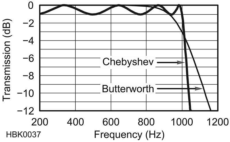
FIGURE 4. Filter responses for a Butterworth and a Chebyshev low-pass filter. Both have the same cutoff frequency of 1,000 Hz but have significant differences in rolloff and ripple in the passband. (Figure courtesy of the American Radio Relay League.)
Depending on what you’re using the filter for, ripple or gradual rolloff might be okay. The different filter families offer choices about how the filter will perform and what effects they have on the signals. For example, hams trying to design an audio filter for receiving the single tones of Morse code (CW) find that a lot of ripple means distortion and smearing of the carefully shaped dits and dahs. At high speeds, that can make the code “tough copy.” In that case, it’s worth allowing a more gradual rolloff so you hear some of the adjacent signals in order for the Morse elements to be reproduced clearly. Each application is a little bit different in what is important.
Brick-wall or Ideal Filters
The filter responses in Figure 2 vary smoothly between the pass-band and the stop-band. This is the way a real filter behaves. Nevertheless, you will encounter references to “ideal” or “brick-wall” filters for which the pass-band and stop-band responses are completely uniform or “flat.” The transition region for such a filter is a vertical line on the response graph with an infinite rolloff. Needless to say, these filters can’t actually be built, although some sophisticated digital filters get close.
Once a filter family is selected, the next order of business is to determine how many “sections” of filtering are needed to meet the performance requirement. The number of sections is the filter’s order — the higher the order, the more filtering is applied to the input signal. Order describes the number of LC or RC pairs in a passive filter, such as in Figure 1A which is a fifth-order filter. Figure 5 shows the effect of cascading three filter sections of Figure 1B’s active RC low-pass filter. You can see the rolloff of the filter increasing as order is increased.
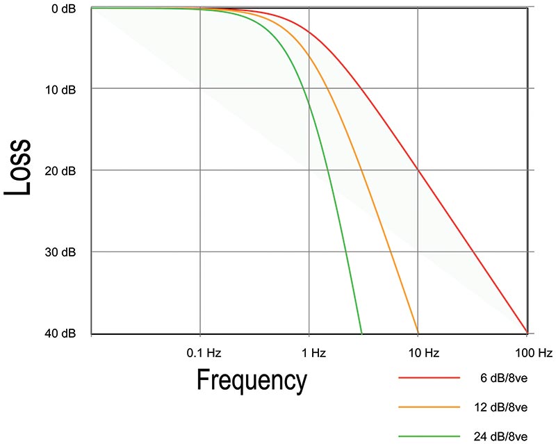
FIGURE 5. The effect of increasing a simple RC filter’s order from 1 to 3. Note the increasing steepness of the filter’s rolloff at higher orders. (Graphic courtesy of Spinningspark at Wikipedia, CC BY-SA 3.0, https://en.wikipedia.org/w/index.php?curid=23488139.)
In general, as order increases, performance can more closely approach the ideal filter’s response. However, filter complexity is increased, tuning is more critical, and component variation and losses can have a more pronounced effect on performance. We’ll cover order in more detail next time.
Common Filter Applications
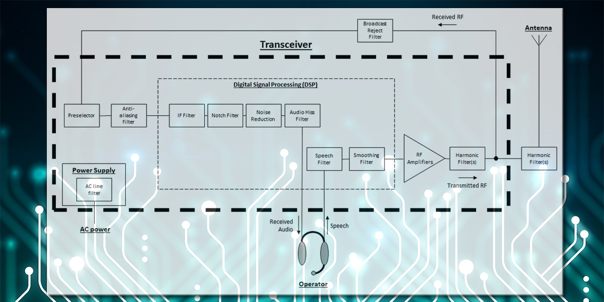
Let’s discuss a few applications for filters. Figure 6 is a block diagram showing where these filters are found in typical ham radio transceivers and accessories.
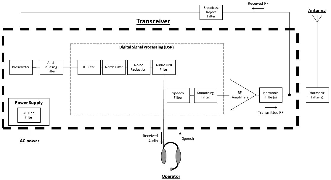
FIGURE 6. A transceiver block diagram showing typical applications of filters for different functions. Filters are used at frequencies from AC power through the transmitted and received RF signals.
Signal-processing filters are more and more likely to be performed by software (DSP), but there are still many analog filter circuits in radio.
- Audio Filters: Along with the CW band-pass filter mentioned above, audio filters are also used to get rid of hum (50 or 60 Hz signals caused by magnetic fields), buzz (caused by 120 Hz rectified AC and ac neutral currents), and high-frequency hiss. FM modulators and noise-reduction circuits also use pre-emphasis (high-pass) and de-emphasis (low-pass) filters for good speech reproduction.
- Noise Reduction: The ability of DSP to make decisions “on the fly” about what signals are noise makes it possible to create “smart speakers” and noise reduction (NR) algorithms that remove undesired portions of the audio output of a receiver. Although they introduce some audible “artifacts,” the result is much cleaner and easier to understand.
- Notch Filters: A type of band-stop filter, notch filters are designed to remove a very narrow range of signals — often just a single-frequency tone caused by a spurious signal or an over-the-air carrier. Analog notch filters require manual adjustment but DSP notch filters can automatically sense the presence of the interfering signal and “notch it out” — even for several signals at once by using current technology.
- Anti-aliasing: When digitizing analog signals, it is necessary for the signals to contain frequency components no higher than one-half the sampling rate. Higher frequency signals will appear in the digitized data as low frequency spurious signals through a process known as aliasing. An anti-aliasing filter is a low-pass filter that removes the undesired high frequency signals. Similarly, when a digital signal is reconstituted as an analog signal, the digital “stairstep” created in the output waveform contains high frequency signals that are removed by another low-pass smoothing filter.
- Preselector: Tunable analog LC band-pass filters at the antenna input that attenuate strong “out-of-band” signals that might overload a receiver, causing it to produce spurious signals. Preselectors are most often used on the HF amateur bands which are shared with or adjacent to powerful shortwave and military stations.
- Broadcast Reject: Instead of band-pass, “BC” reject filters usually have a notch or band-stop response. They are used in the vicinity of strong fixed-frequency AM, FM, or TV stations. A similar filter can be used to attenuate commercial paging or repeater signals.
- Harmonic-rejection Filter: FCC rules require the spurious outputs from amateur transmitters to be at least 43 dB (20,000x) less powerful than the intended transmitter output. These low-pass filters are placed between the output of an RF amplifier and the antenna connection. The cutoff frequency of the filter is selected according to the operating band of the transceiver. External low-pass filters are also used to provide additional attenuation of harmonics and other spurious signals that might interfere with broadcast TV reception. (With TV stations having moved to UHF channels for DTV signals, TV interference is much less of a problem these days.)
- AC Line Filter: Low-pass filters that attenuate RF signals on the hot and neutral lines of an appliance’s AC power connection. Line filters reduce both on RF signals generated inside the appliance that shouldn’t get out to be radiated and on RF signals picked up on the power wiring that might disrupt the appliance. These line filters usually do not filter the equipment ground (a.k.a., the third-wire or green-wire ground) conductor so additional filtering — such as from a ferrite core — may be necessary. (See Ham’s Wireless Workbench columns on ferrite and RFI for more information about this kind of filtering.)
Filter Design Resources
Many books have “canned” filter designs for various common applications. If you are careful to use the same type of component and circuit layout, you’ll probably get acceptable results. Beginners should start with pre-designed filters. As you progress, you’ll be presented with the need to “roll your own” filter. Along with the Tonne Software programs we’ll be using in the next article, there are some tried-and-true resources for the experimenter. For serious readers, the various editions of Arthur Williams’ Filter Design Handbook are widely available as used copies.
If you’re looking for more of a “plug and chug” solution, the venerable Active Filter Cookbook by Don Lancaster in its various printings will provide design formulas and examples for filters in the audio range. Finally, for RF filters, the ARRL Handbook’s chapter on Analog and Digital Filtering provides theory and projects through the microwave range with a long list of references and additional supplemental information online.
Do Filters Have to Be Circuits?
Analog filters with Ls, Cs, and Rs are very common but they aren’t the only electronics that can perform filtering functions. Indeed, there are no perfect circuits for which frequency doesn’t matter, so technically, every circuit is a filter! However, there are a few notable non-LCR filters you should be aware of:
- Crystal and Mechanical Filters: Once the best available passive filters for receiving RF signals, these filters used quartz crystals and precisely machined mechanical resonators. A crystal roofing filter is still used in many receiver designs to improve strong signals from interfering in crowded conditions.
- Stubs: Resonant sections of feed line can act as band-pass and band-reject filters. Books on transmission lines and antenna systems will explain how these work.
- Waveguides: Sections of waveguides with internal baffles or tuning screws can be very effective filters at microwave frequencies.
- Antennas: Not only can antennas act as frequency-dependent filters with preferred frequencies, but they can act as spatial filters too!
Why are Analog Filters Still Necessary?
While you’ll find digital filters taking over more and more filtering chores, analog filters are still the only practical choice for many roles. Obviously, at high power levels — such as for transmitters and duplexers — low-loss inductors (L) and capacitors (C) are required. The selection of appropriate components is an art in itself for these circuits.
Less obviously, analog filters are also required at very low signal levels where a digital circuit may not have enough resolution in bits to represent the signal, and at very high frequencies where the samples can’t be taken fast enough. Digital filters also require a fair amount of supporting electronics and might be too expensive.
Analog filters will be with us for quite a while!
Designing Filters with ELSIE
In this article, I’ve presented some filter basics to give you a better understanding of how filters behave and are specified. It wouldn’t be very nice to leave you hanging without some practice, however. So, in the next article, we’ll experiment with a very capable suite of filter design software.
ELSIE (a play on “LC”) is provided by Tonne Software (Jim Tonne W4ENE is a long-time contributor to the ARRL Handbook and other ham radio endeavors), along with several filter design utilities.
You’ll find that filters are well within your ability to design and build! NV