Developing Professional Soldering Skills with the Use of an Educational Kit
Soldering skills are required by industry manufacturing electronic products as well as electronics enthusiasts developing new prototypes. What distinguishes the skilled solderer is the ability to perform work at a level that insures reliability.
Attaining these skills doesn’t take industry approved soldering classes, expensive rework stations, or sophisticated inspection systems. Preferred quality, the industry standard can be obtained at home with basic soldering equipment as long as the project was designed with the tools of the builder in mind, proper techniques were used, and acceptability standards were observed.
The Super Awesome Cube kit that I’ll discuss here consists of six interconnected double printed circuit boards (PCBs) connected together to form a three-dimensional LED display.
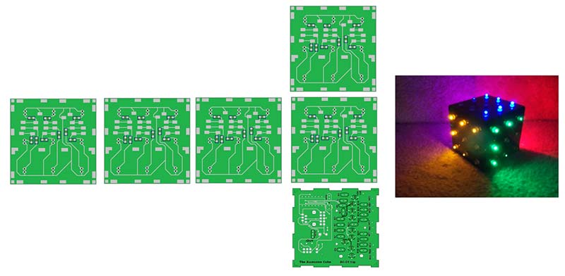
Figure 1. The six circuit boards form a multi-sided programmable light display.
The cube consists of five LED side boards that make up the cube structure connected in parallel to a controller. Each side board has nine LEDs. The color of the LEDs is selectable by the builder. The fully programmable light sequence is determined by the PIC controller.
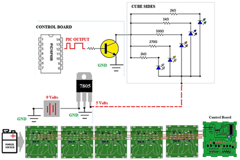
Figure 2. The nine outputs of the PIC each control one LED on the five side boards. The color of the LED is selectable by resistor choice.
The circuitry of the cube is relatively simple; there are nine identical circuits controlled by individual outputs of a PIC microcontroller. The output is displayed on all sides of the cube simultaneously.
Building the kit will provide experience with lead preparation, wire to pad soldering, through-hole soldering, surface-mount soldering, and structural soldering.
Step-by-step instructions allow builders to do most of the work with the boards flat against the work surface. The order of assembly avoids situations of obstructed soldering. Circuit testing and a comprehensive check list provide quality control.
The kit introduces the builder to basic coding and contains spare parts which allows for individual design options.
The Super Awesome Cube is the brainchild of Jeff LeSueur BSEE, M.Ed., who is an educator, electronics engineer, and entrepreneur. The kit is the product of his many years in the classroom.
Start the project in a clean, well lit, well ventilated workspace. Set out your tools and arrange the boards on the workspace. Be sure to take into account the final assembly.
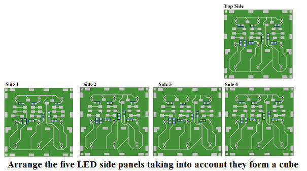
Figure 3. Start with panels flat against a surface for SMT installation.
Start with the surface-mount resistors. SMT (Surface-Mount Technology) components should be installed before other components when there are few obstructions.
Plug in the iron, wet the sponge, wait for the iron to heat up, and clean the tip. Ideally, you should use a temperature controlled iron. If not, you can use solder to verify the iron temperature. The solder should melt instantly upon touch by the soldering iron.
The soldering iron loses a little heat after each use, so it’s best to wait a few seconds between uses. Solder that is left on a soldering iron tip too long will oxidize, causing poor connections. Clean and tin the tip often.
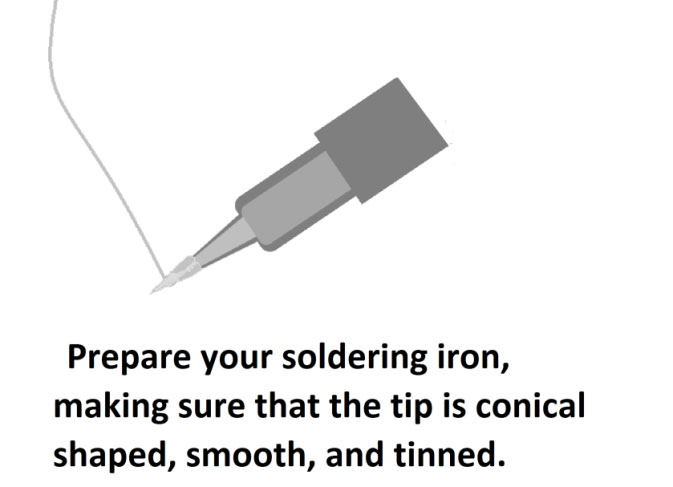
Figure 4. Solder should melt instantly upon touch. Coat the tip of the iron with solder.
Tinning
Whatever it is you’re soldering, you should 'tin' both contacts before you attempt to solder them. This coats or fills the wires or connector contacts with solder, so you can easily melt them together. To tin a wire, apply the tip of your iron to the wire for a second or two, then apply the solder to the wire.
The next step is to tin the pads. This should be done with a freshly tinned iron. The resin core solder provides the flux for this operation. The solder coating should be thin to aid in the placement of the surface-mount components.
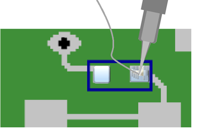
Figure 5. Tin pads of the surface-mount resistors.
Excess solder should be removed from the pad with solder braid. When removing solder with solder braid, use flux and a freshly cleaned (un-tinned) tip.
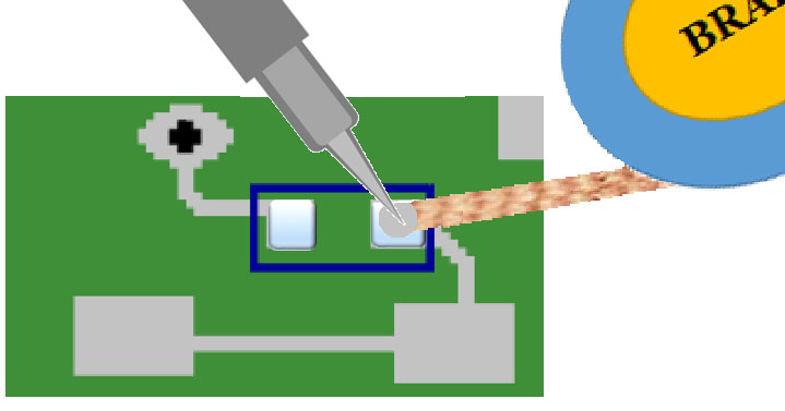
Figure 6. Remove excess solder.
Soldering Flux
Soldering flux is a chemical which is used to prevent oxidation of metals when joining them. Soldering flux is activated by the heat of the soldering operation to remove the last layer of oxidized metal so that the solder will wet the base metal and produce a good joint.
Solder Braid
Also called solder wick, solder braid is a ribbon of extremely fine copper strands woven together. It’s usually supplied on small reels of about 1.5 m of braid and comes in a variety of widths.
The board is now ready for component installation. Components should be handled with small tweezers and be held in position with a pick.
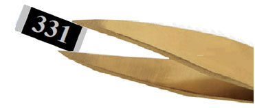
Figure 7. Surface-mount components should be handled with small tweezers.
Components should be centered on the tinned pads with the numbers up reading from left to right.

Figure 8. Components should be centered on the pads.
While holding the component in position, flux the connection and heat with a well tinned iron until the solder flows, forming a nice fillet. The soldering iron tip should fit the pad, the time of contact should be short, and the finished joint should be shiny.
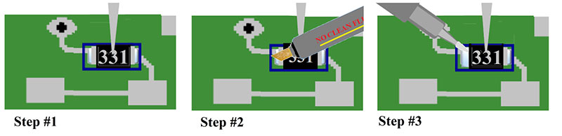
Figure 9. Hold, flux, solder.
Solder Fillets
The solder joint surfaces are smooth, non-porous, and undisturbed, with a finish varying from satin to bright. The fillet completely wets all elements of the connection and is concave.
Excess heat can damage the laminated board. Heat is not just a factor of the temperature of the iron but also of the time of contact. Wait a second or two between heat applications.
When the joint cools, the component will be secure so there’s no need to hold the component when soldering the other side. First, place the soldering iron on the joint and then position the solder between the lead and the tip of the iron. The solder should melt quickly forming a nice fillet. Remove the solder before removing the iron.
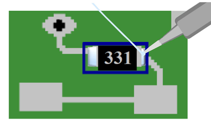
Figure 10. Place heat first, then solder. Remove solder, then heat last.
A joint should appear shiny and wetted to the pad.
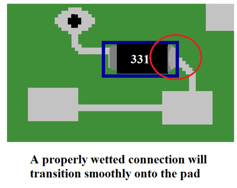
Figure 11. A properly wetted connection.
Inspect connections carefully with a magnifying glass.
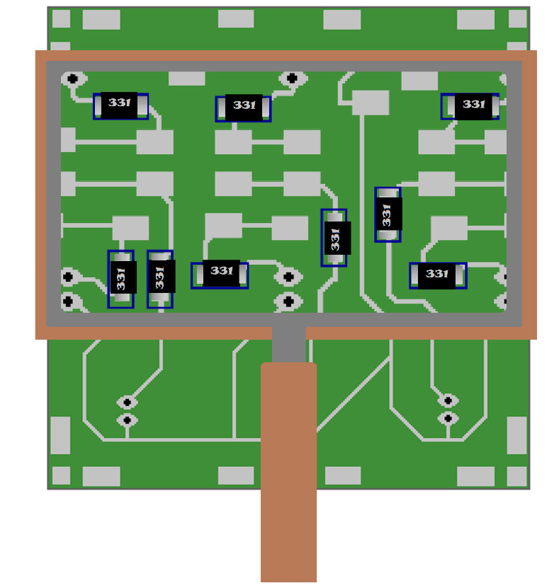
Figure 12. Board inspection.
Inspect the quality of the solder joint, the positioning of the resistor on the pads, and the proper resistor values.
If the iron is removed before the solder, it can form an icicle on the joint which is a small solder protrusion. If the soldering iron is not clean or insufficient flux is used, it can result in solder balls or blow holes.
The iron should be cleaned and re-tinned regularly through the process. It’s important to always apply flux whenever re-heating a joint.
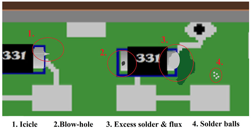
Figure 13. Solder abnormalities.
After the visual inspection, check the resistance to verify the connection. Read the resistance from a node on one side of the resistor to a node on the other side. This will verify both the soldered connection to the trace and the value of the resistor.
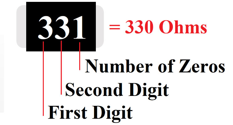
Figure 14. Reading surface-mount resistor values.
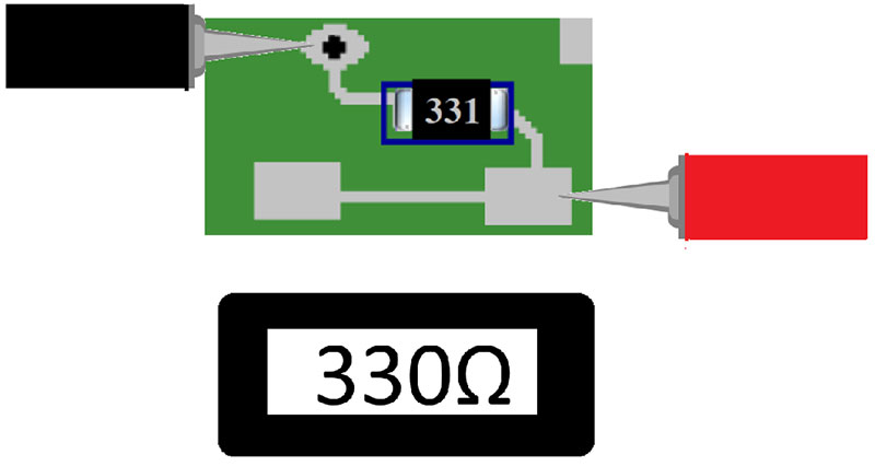
Figure 15. Read resistance from node to node.
Once the surface-mount resistors have been installed, it’s time to interconnect the boards. Cut the jumper wires to size and trim about a quarter inch of insulation from each end.
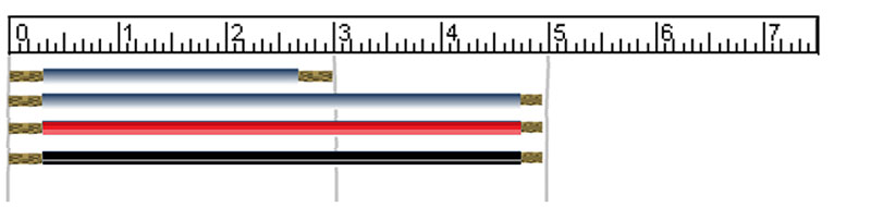
Figure 16. Trim jumper wires to length.

Figure 17. Tin the wires.
Once the wires are cut and tinned, they’re ready to be tacked to the pads. Note that there are multiple pads on many of the nodes. All pads on a node are the same point electrically. If a node has multiple pads, it means the node connects to more than one wire.
When testing a circuit during assembly, you should test from node to node. When troubleshooting a circuit, it may be necessary to test from pad to pad in order to find a broken trace.

Figure 18. This resistor node has two pads.
Tin the pads before tacking on wires. It’s not necessary to flux the pads before tinning because of the flux contained in the solder.
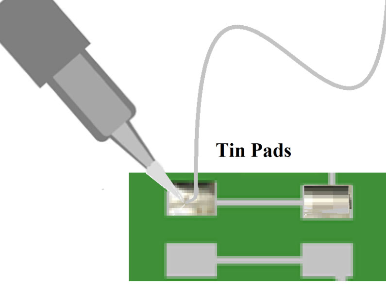
Figure 19. Pre-tin pads.
When tacking a wire to a pre-tinned pad, use a well-tinned iron, flux the pad, hold the wire in place, and heat until the solder flows. Hold the lead steady till the solder solidifies. Failure to do so will result in a cold solder joint that has a dullish appearance.
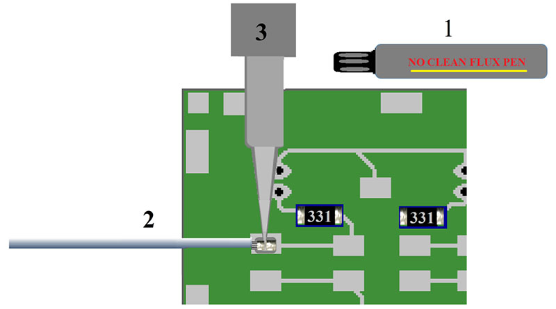
Figure 20. Tacking wires onto the pads.
Let the connection cool for a few seconds, inspect the joint for sufficient solder, and gently pull on the wire to insure a good mechanical connection. After both sides of a wire are connected, test the connection from board to board.
Follow these step-by-step instructions working on the boards from left to right until you have all the LED boards connected in parallel. The wires from the left should be attached to the leftmost pad on the node.
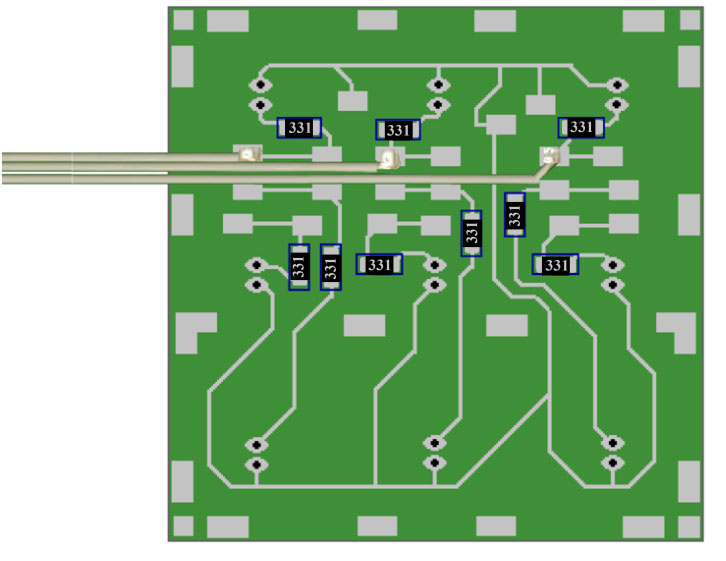
Figure 21. Wires to the left should be connected to the leftmost pad on the node.
Note! Wires from the right should be connected to the rightmost pads on their nodes, just as the wires from the left should be connected to the leftmost pads on their nodes.
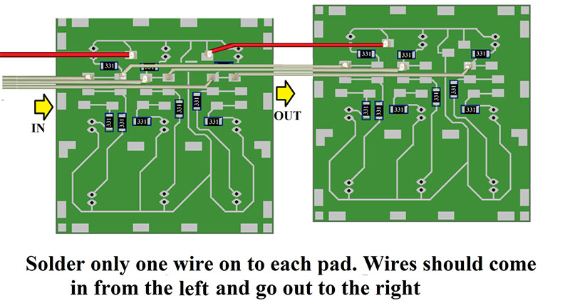
Figure 22. Wire systematically from left to right to avoid obstructed soldering.
Once the surface-mount resistors have been installed and the side boards have been interconnected, it’s time to mount the LEDs. The LEDs are mounted on the front side of the board through holes in the circuit board.
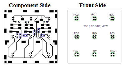
Figure 23. Component side and flip side.
Before mounting the LEDs, it’s important to test them. The removal and replacement of any part will impact the reliability of the final assembly. When testing the LEDs, be certain to identify the anode and the cathode leads.
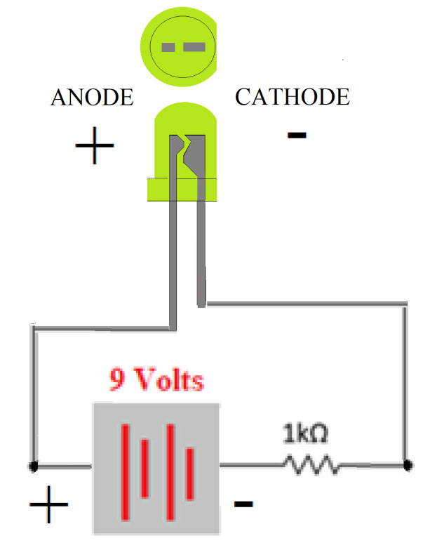
Figure 24. LED testing and lead identification.
Slide the leads through the holes from the front side, paying attention to polarity until the base of the LED is flat against the surface of the board. Bbend the lead to hold it in place. Mount all nine LEDs before soldering to give yourself a flat surface.
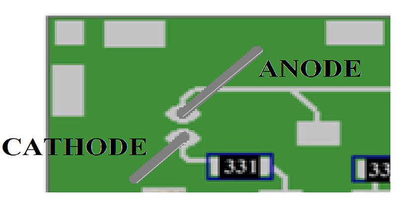
Figure 25. The cathode lead; the shorter lead should be going to the node with a resistor.
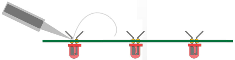
Figure 26. Mount all the LEDs on the board so you have a flat surface before soldering.
Before soldering, verify the values of the resistors, check the polarity of the LEDs, and flux all connections. After soldering, trim and inspect connections.
Once the LEDs have been installed onto all five boards, it’s time to test the LED circuits. The red lead coming into the first board should be connected to the positive terminal of the nine volt battery. The nine white wires coming out of the fifth board should be connected one at a time to the negative terminal of the battery. As each white wire is connected, one LED on each board should light.
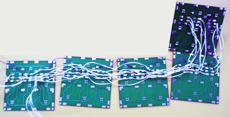
Figure 27. LED boards wired assembly.
After the LED side boards are completed and tested, it’s time to assemble the control board. Be sure and take note of the top and bottom sides of the board.
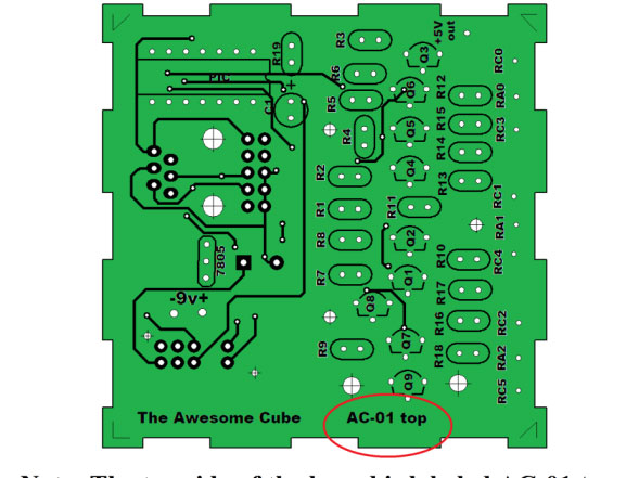
Figure 28. The top of the board is labeled “AC-01 top.”
Install the remainder of the components onto the control board following the step-by-step instructions.
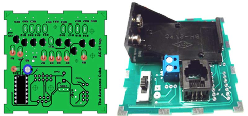
Figure 29. Install the components.
Install the resistors “standing up” so that the color code reads down from the top (Brown-Black-Red) and that the body of the resistor faces the IC.
Note! The placement of the resistors is not a functional requirement but is an aid in future testing and troubleshooting.
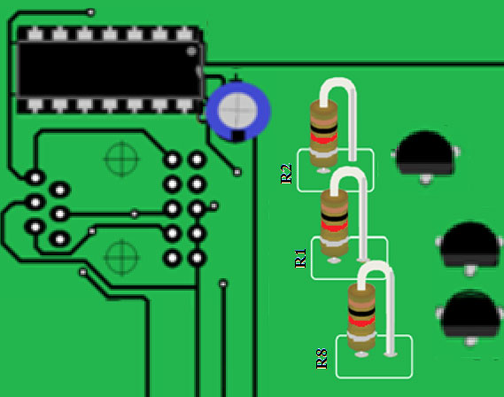
Figure 30. Install resistors standing up, all oriented the same.
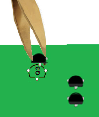
When installing transistors, follow the silkscreen outline.
 \
\
Figure 31. Place transistors in accordance with the silkscreen.
Place the heatsink on the transistor while soldering to help dissipate the heat.
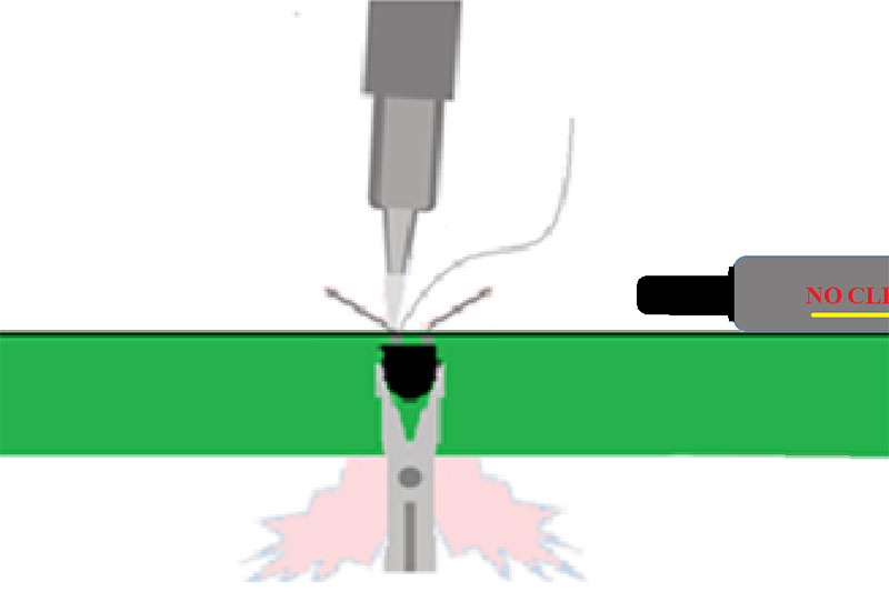
Figure 32. Use a heatsink to avoid overheating the transistor while soldering.
Install C1 (the 100 μF capacitor) so the base is flat against the board.
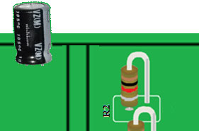
Figure 33. Push leads of capacitors through holes till the base lays flat against board.
Note! Be aware of the polarity: “+” is the longer lead of the capacitor; the striped side of the capacitor is negative.
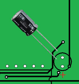
Figure 34. The longer lead is the positive lead of the capacitor.
Clinch the capacitor leads to hold the capacitor in place, and then flux and solder the connections.
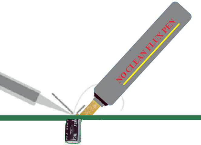
Figure 35. Flux and solder the capacitor leads.
Install the IC socket before inserting the chip. Match the notch in the socket to the notch on the silkscreen.
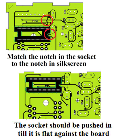
Figure 36. Installing an IC socket.
Turn the board over and clinch the corner leads to hold the socket in place.
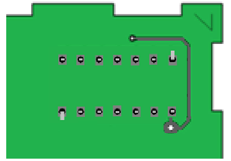
Figure 37. Clinch the two corner leads to hold the socket in place.
Flux and solder the socket leads alternating sides to distribute the heat.
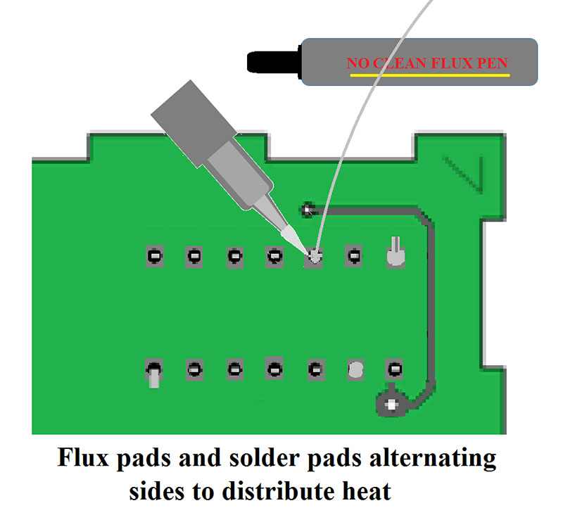
Figure 38. Solder the socket leads, alternating sides to distribute heat.
Check the voltage on the socket before inserting the chip. Disconnect the battery and slide the chip into the socket, making certain pins align and seat properly.
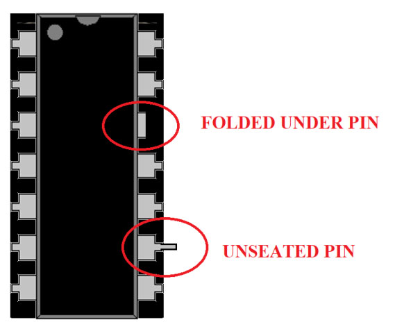
Figure 39. Properly seated pins should not stick out or be folded over.
Wire the control board to the side boards, making certain the solder connections are good and the wires are held firmly in place. Now, install the nine volt battery, turn the switch, and observe operation of the boards. All the lights on all the side boards should turn on and off in a pattern.
The electrical assembly is complete and tested. Do a visual inspection before final assembly. After final assembly, the wiring and much of the circuitry will be internal to the cube.
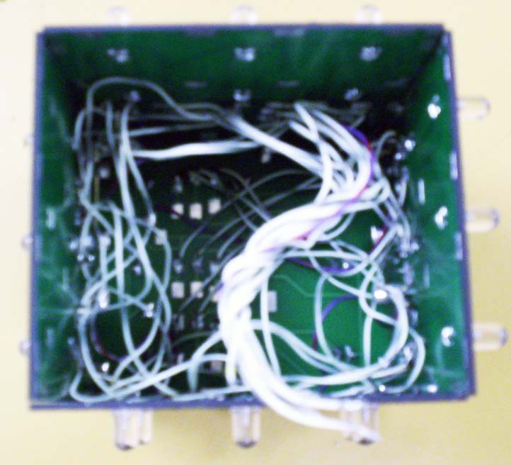
Figure 40. Much of the cube wiring is internal.
In the final cube construction, solder the sides together using a 90° block or reference. Strive to make the cube perfectly square. The edges should meet with no overlap and should be connected together using the board’s edge pads.
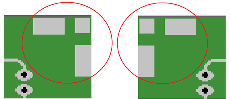
Figure 41. Boards are connected together by utilizing the edge pads.
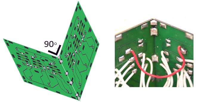
Figure 42. The edges should be connected at a 90° angle ...

Figure 42B. And the edges of the boards should not overlap.
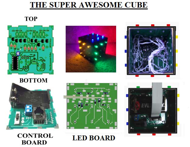
Figure 43. The Super Awesome Cube provides a variety of challenges.
The Super Awesome Cube exposes the builder to soldering standards and the importance of visual inspection and circuit testing. Even though the project is electronically simple, it provides the builder with an array of soldering challenges and hours of soldering experience.
The combination of hardware and software makes the product fun and entertaining. The programmability allows the builder to vary the display and practice their coding.
This is a product that the builder will want to keep for years. And, those years of service will be evidence of the skill and workmanship of the builder. NV