I have seen several simple alarm circuits in Nuts & Volts through the years, but this one is a little different in that it connects directly to popular lines of Genie garage door openers.
While I use it with a model IS550, it should work with many Genie models (all Intellicode screw drive models from 1997-present) that share a common sequencer board #31184R. This should include models CM8700, CM8600, CM7600, PRO95, Series II, ISL950A, IS550, GCL, H6000A, H4000A, and IS. If in doubt, check that the opener switch connects the #1 and #2 screw terminals to open and close the door, and that the safety beam signal is on terminal #3 and is a 3 ms pulse train that is interrupted when the IR beam is broken.
I cannot see my garage from my house, so I wanted the opener switch to light when the door was open and have an audible alarm if anyone entered the garage. The switch LED is detected from the opener’s close limit switch, and the alarm is triggered from the Genie’s safety IR beam. While it is easy enough to step over the safety beam, I felt the common nature of these devices was enough to detect a casual intruder or a child entering the garage. I don’t think I could get a car by one.
The connection is a four conductor wire from the opener (Figure 1) to a junction box (Figure 2) near an AC outlet where the 12 VDC is introduced.
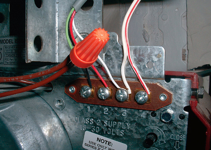
FIGURE 1.
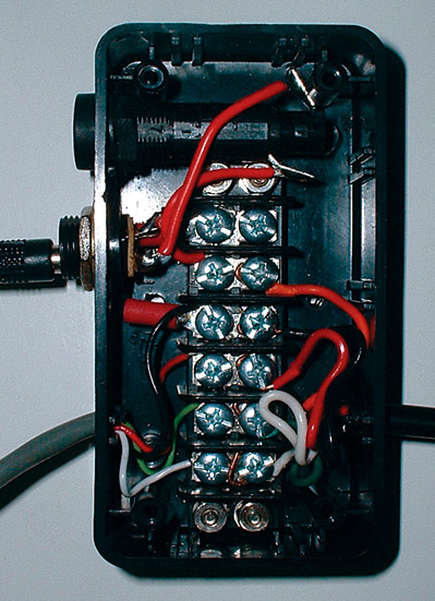
FIGURE 2.
Three wires connect directly to the Genie’s screw terminals; the fourth must be spliced into the wire from the close limit switch. The rest of the wire run is five conductors to the alarm.
I used a sprinkler type of solid conductor wire from Home Depot. I placed my junction box inside the house, but it could be in the garage or eliminated entirely if the 12 VDC can reach the garage opener. In this case, just run five conductors the whole way.
Part of my decision to use a junction box was that I wanted the power supply fused during prototyping without having to use the space inside the alarm itself. The LED is mounted in the opener switch (Figure 3).
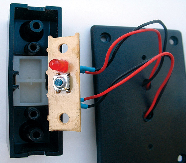
FIGURE 3.
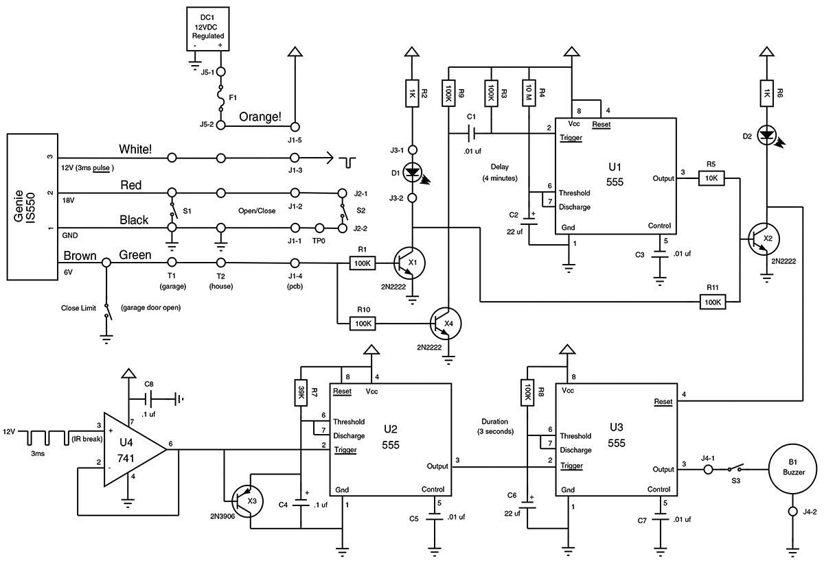
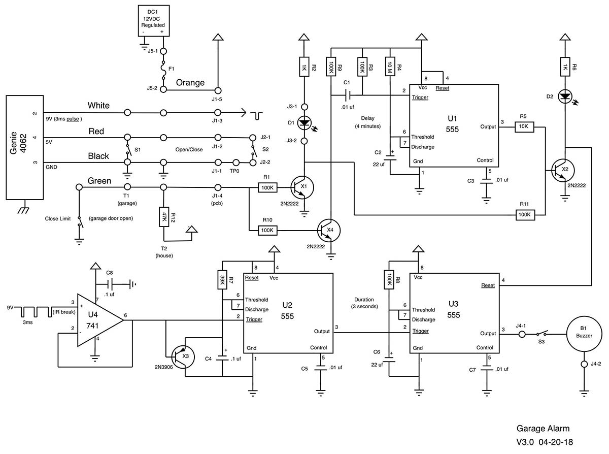
Opening the garage door turns on transistor X1, lighting LED D1, and triggering U1 to provide an alarm delay for normal garage usage. After about four minutes, the output of U1 (inverted through X2) goes high, enabling U3 to sound an alarm. If the safety IR beam is broken, the Genie’s missing output pulses are buffered by U4 and detected by U2 to trigger the alarm for about three seconds.
In my original design, the alarm sounded after the garage had been left open for a few minutes. This pretty much drove me crazy. Version 2 triggered from the IR beam but left the alarm active at all times except for the initial delay; I figured that nobody could break the beam with the door closed. I found that the alarm would occasionally sound (usually in the middle of the night), sending me stumbling to see if the door was open. I don’t know if this was from transient missing pulses or maybe a spider in the garage, but it was very annoying. This latest design configures X2 as a NOR gate so that the alarm is only active with the garage door open.
LED D2 is for troubleshooting. It is inside the case, and hopefully you will never see it (you can substitute a jumper if you wish). D2 lights when the alarm is disabled, either because the door is closed or during the delay period. With power applied, either D1, D2, or both should always be lit.
The mechanical construction is compact for aesthetic reasons (Figure 4), the circuit board is 1.75” x 2.00” (Figure 5) and the layout is available at the end of this article in the downloads, with all files necessary for construction. All of the components are widely available. I have also handwired this board using a RadioShack #276-159B prototype circuit board, but it is very tedious.
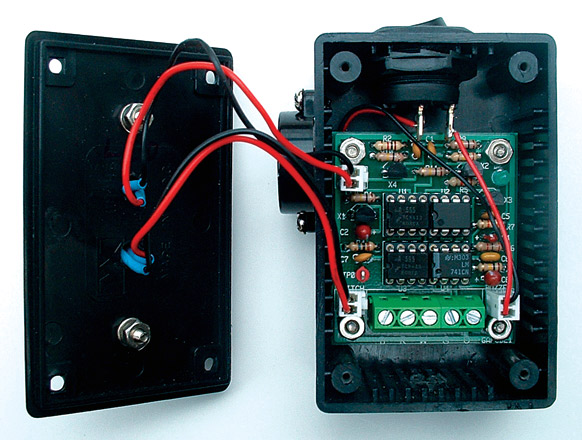
FIGURE 4.
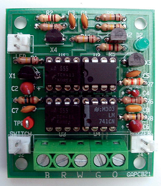
FIGURE 5.
For the most important feature, there is an alarm kill switch on the top of the unit for those times when you actually want to work in the garage without annoying everyone in the house! NV
Parts List
| Item |
Description |
Manufacturer/Part # |
| R1, R3, R8-R11 |
100K 1/4W |
|
| R2, R6 |
1K 1/4W |
|
| R4 |
10M 1/4W |
|
| R5 |
10K 1/4W |
|
| R7 |
39K 1/4W |
|
| C1, C3, C5, C7 |
01 µF ceramic |
|
| C2, C6 |
22 µF tantalum |
|
| C4 |
.1 µF tantalum |
|
| C8 |
.1 µF ceramic |
|
| D1 |
LED, T1 3/4 size |
|
| D2 |
LED, T1 size |
|
| X1, X2, X4 |
NPN transistor |
Fairchild/PN2222 |
| X3 |
PNP transistor |
Motorola/2N3906 |
| U1-U3 |
Timer |
Fairchild/LM555 |
| U4 |
Op-amp |
National/LM741 |
| B1 |
12V piezo buzzer |
|
| S1, S2 |
SPST mom. switch |
Genie/GWB34690-R |
| S3 |
SPST rocker switch |
|
| J1 |
5 pos PCB block |
Altech/AKZ250/5 |
|
J2, J3, J4
|
2 pin header
2 pin female
|
Molex/22-23-2021
Molex/22-01-3027
|
| J5 |
2.1 mm DC jack |
ValuePro/DPJ-021A |
| TP0 |
PCB test point |
Keystone/5005 |
| T1 T2 |
4 terminal block |
Cinch/4-140 |
| F1 |
.5A fuse |
|
| FH1 |
Fuse holder |
|
| DC1 |
12 VDC transformer |
ReliaPro/DDU120050 |
| Case1 |
3.125 x 2.0 x .875 |
ValuePro/H2855 |
| Case2 |
4.875 x 2.5 x 1.5 |
ValuePro/H2853 |
| PCB |
Circuit Board |
Advanced Circuits |
| Screws |
4-40 w/nuts/washers/pan/round heads |
|
Corrections
Garage Alarm Update
I built the garage alarm (described above) using a Genie garage door opener that was originally published in the November 2007 issue of Nuts & Volts. The opener finally died but I am glad to say that the alarm lives on! (Photo 1)
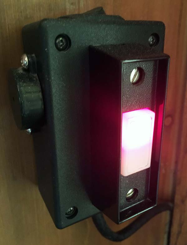
Photo 1.
I replaced the opener with a new Genie model and they had not made any changes in the IR beam pulse timing so the alarm circuit worked without modification.
The door open indicator LED however, was originally keyed from a physical limit switch that is no longer present on the new Genie model. As well as the indicator, the switch resets the alarm so it is necessary for operation. To account for this, I screwed a new long lever micro switch to the rail (photo 2) and attached a bolt to the carriage to push it closed. I was not sure about the quality of this switch, so I ordered a few extra and mounted it with the screws facing outward. With the quick connects, I can swap it out in a few minutes.
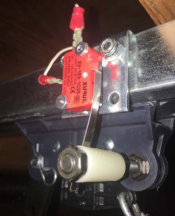
Photo 2.
The original Genie limit switches are widely available, though they use the rail for signal ground. On the new model, the rail was connected to power ground and the signal ground appears to be isolated.
The original limit switch had 6 volts on it so I added a 47K resistor R12 between the switch and the alarm’s Vcc supply. I did this in the junction box where the wire enters the house (photo 3). It could also be screwed between J1-4 and J1-5 in the alarm itself.
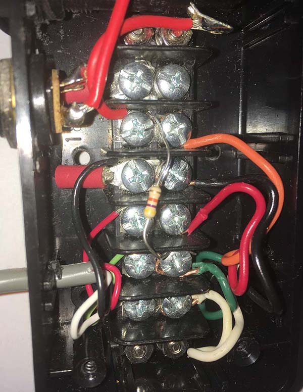
Photo 3.
All is working well again and I hope to outlast another opener!
Downloads
Garage Alarm (Layout with all files necessary for construction)