In most linear power supplies, voltage and current limits are entered with rotating knobs. For faster and higher precision, I wanted to design a lab power supply for my bench with voltage and current limits entered via a keypad. I included a microcontroller to take care of the keypad input functions but wanted the basic supply to be linear — no switching and less noise!
This article will show you all the steps I used to design a programmable supply.
Analog Circuit
With a target spec of 0-30V and 0-1A, I had to find high voltage capable (< 35V) components for the analog section of the design. I chose Microchip products: the MCP6V51, a line of high voltage op-amps; and the MCP6C02 high side current sensors that would fit my design criteria.
The design is a conventional error integrating feedback circuit both on the constant voltage side and the constant current side. The selected op-amps can handle voltages up to 49V and exhibit low drift with good DC performance. The resistance values are kept low (10K Ω) and equal on both the inverted and non-inverted inputs to minimize any offset errors.
These resistors provide an RC filter function together with 1 µF capacitors (C1, C2) to remove any residual noise from the DAC’s (digital-to-analog converters) outputs. The set point voltages are provided by the microcontroller’s DAC’s, 0 to 3.3V, so the input voltage feedback must be scaled to that level by R1, R2.
On the current side, the current measurement is preferably on the high side to maintain a common ground and uses a current sense resistor value as small as possible to minimize voltage drop and power dissipation. The high side current sensor (MCP6C02) meets these criteria.
It can operate up to 65V and with a gain of 100, it allows a low value current shunt. Given the 1A maximum current target in this application, the shunt resistor value should be on the order of 30 mΩ, that will produce a feedback voltage of 30 mΩ * 1A * 100 = 3.0V. The resistor is implemented using a ~ 2.5” length of 40 mil wide copper trace on the PCB (printed circuit board). Refer to Figures 1 and 2.
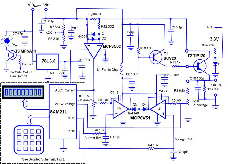
FIGURE 1. Analog schematic.
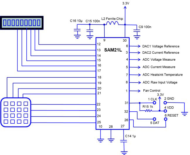
FIGURE 2. Controller schematic.
The load to a lab power supply can be anything from open to a dead short, and therefore extra protection components must be added. The back-to-back connected 1A general-purpose diodes (D1, D2) together with the current-limiting resistor R3 ensure that the differential input voltage of the current sensor chip stays below the 1.2V maximum rating under any condition.
The integrating capacitor, C3, on the current amplifier must be several magnitudes larger than on the voltage side to compensate for the added propagation delay by the current sense amplifier to keep the loop stable. A second DAC channel from the microcontroller is providing the set voltage (resulting in set current) for the current error amplifier U2.
The outputs of the two amplifiers are logically OR’ed together with the small signal diodes D3 and D4 to drive the output Darlington pass transistors. The OR function will decide if the supply is in constant voltage mode or in constant current mode.
Microcontroller Circuit
The microcontroller controls the keypad and the LCD display. It will also generate the reference voltage levels for the analog control loops. This require two channels of DACs with good resolutions. An ADC (analog-to-digital converter) will be used to measure various parameters of the supply.
The Atmel SAML21 was selected based on having two channels of 12-bit DACs complemented with a 12-bit ADC in a small 32-pin TQFP package. A full 12-bit DAC is not required for the application; however, it’s good to have extra headroom as some precision is lost in the specification and in the rounding error when the firmware is calculating the set values.
My target resolution was 100 mV for the constant voltage control and 1 mA for the constant current setting which is easily achieved in 12 bits. My first intention was to use the controller only for the keypad, the LCD display and to calculate the set values. As a 12-bit ADC is available on chip, I took advantage to add measurements of several parameters of the supply: set voltages and current; actual voltage and current; input raw voltage to the pass transistor; and temperature controlling a cooling fan. Based on these measurements, total input power, total power to the load, and power dissipation of the pass transistor can be calculated.
Firmware
The code is written in C and there are two variations of the driver: one that provides the basic functions such as PowerSupplyBasic.c, setting and measuring the voltage and current; and a full version with PowerSupplyFull.c that in addition includes measuring the heatsink temperature, turning on/off a fan depending on the heatsink temperature, displaying the input voltage and power, and finally displaying the power dissipated in the pass transistor.
These drivers are available in the downloads and should be added in a Studio 7 project together with the PowerSupply.h header file.
The program is compiled using the Studio 7 IDE (integrated development environment; version 7.0.129) and an Atmel ICE development tool was used for programming and debugging. The programming pins on the PCB do not fit the standard connector that comes with the programmer, so a new connector must be wired to ensure the pins match the pins shown in Figure 2 and the in the board layout.
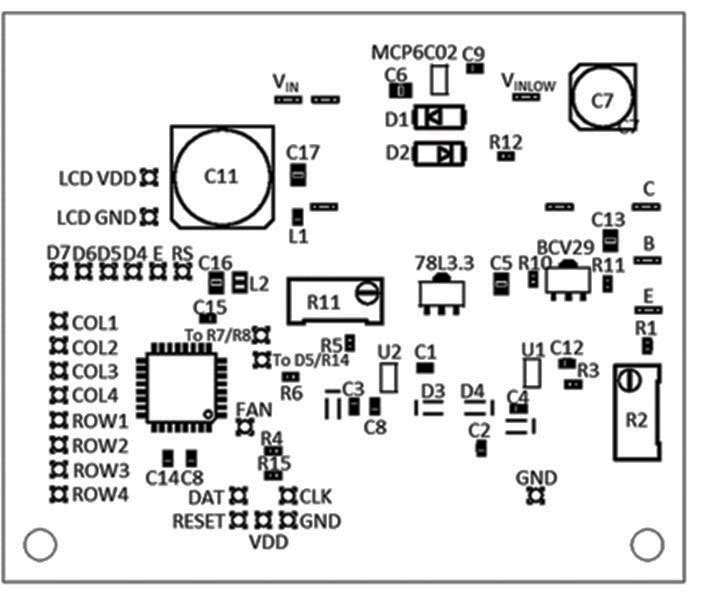
32-bit power supply board layout.
At startup, the voltage is set to 0V and the current to 50 mA. The display shows voltage set and voltage measured on the first line, and current set and current measured on the second line.
If the full version of the driver is installed (and the associated hardware as explained below), the auxiliary functions can be displayed.
The key interface functions as follows:
| Press Key |
Enter |
Press Key |
Action |
| A |
Voltage XX*x |
# |
New Voltage Set |
| B |
Current X mA |
# |
New Current Limit Set |
| A |
|
C |
Clear Voltage |
| B |
|
C |
Clear Current |
| The Full Function version will add the following functions: |
| D |
1 |
|
Display Chip Temperature and Heatsink Temperature |
| D |
2 |
|
Display Input Voltage and Power |
| D |
3 |
|
Display Power Dissipation |
Hardware
Breakdown voltages for surface-mounted passive components are generally not a concern as most circuits are operating at a low voltage. This application is an exception and therefore it’s important to pay attention to this parameter.
I have specified some of the capacitors used on the PCB as minimum 50V parts. There are good reasons to use 50V (or higher) ceramic capacitors in all positions, if the package size is available. The ceramic chip capacitor’s capacitance is voltage dependent; the capacitance is lower the closer it gets to the maximum operating voltage.
I’ve provided a separate VDD feed to the L78L3.3 voltage regulator, VinLOW. This regulator has a maximum input voltage of 30V. If your raw power supply is higher than that, the VinLOW must be fed from a separate lower voltage supply or a voltage dropping component must be inserted between Vin and VinLOW. A resistor or a zener diode will work well. Current consumption for this circuit is around 25 mA, which is mostly consumed by the backlit LED in the display.
If the full version will be built, the diode D5 should be glued to and in good thermal contact with the pass transistor (TIP140). Resistor R14 provides an approximate constant current of 100 µA so the diode voltage drop is only depending on the temperature; typically, 0.7V and -2 mV / °C. However, there’s a lot of variability to both the absolute voltage level and temperature coefficient (slope) from diode to diode. Therefore, this parameter needs to be individually calibrated in the software.
The SAML21 have a built-in temperature module that is calibrated from the factory, so this will provide a good starting point.
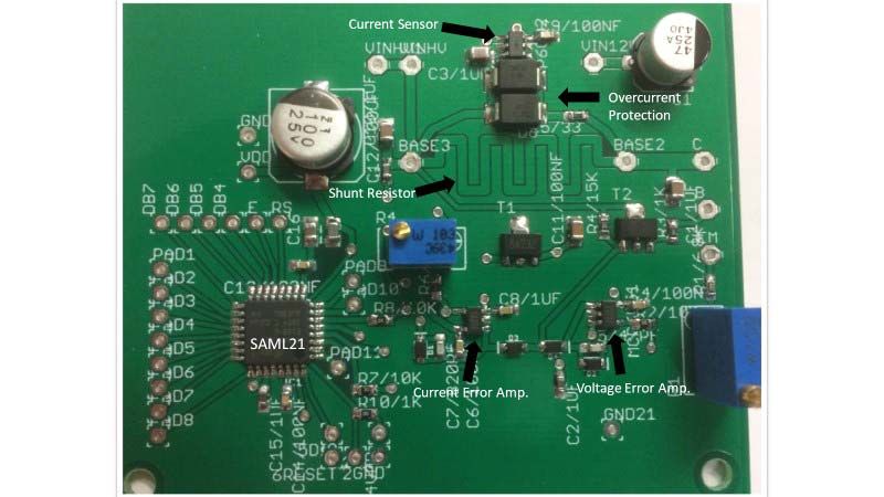
FIGURE 3. Printed circuit board.
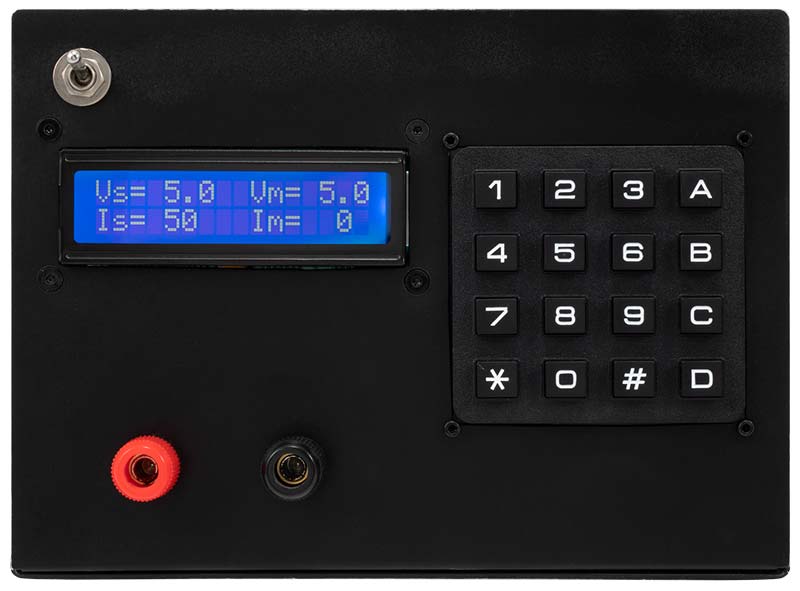
FIGURE 4. Output display.
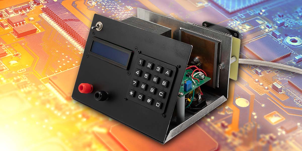
I made the case from aluminum sheeting and the completed supply is shown in Figure 5.
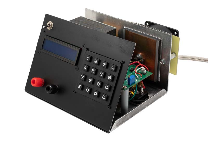
FIGURE 5. Bench power supply.
Variations
If you only consider building the basic version without the heatsink fan, the following components are not needed: T3, R9, R14, R7, R8, D5.
I had a transformer available that would give about 40V rectified voltage at no load and has a current rating of 1A. Therefore, I set the regulated maximum voltage to 30V and the maximum current to 1A. The pass transistors need to have a combined 4-5V of collector to emitter voltage at full load.
If you have a transformer available that will give a lower or a higher voltage, it’s possible to modify the code that sets the DAC’s reference voltage. If the desired voltage change is outside of the adjustment range of trim potentiometer R2, the scaling value for resistor R1 must be changed such that the voltage at the inverting input on U1 is less than the minimum DAC high level (VDD – 150 mV) at full output voltage of the supply.
The maximum voltage limit is set by the maximum voltage specified for the op-amps and/or the pass transistors. With the selected op-amps, the unloaded input voltage must stay below 49.5V, minus a safety margin. The upper current limit is set by the current handling capabilities of the pass transistor.
The TIP140 is good for 10A of continuous collector current, but it’s possible to add pass transistors in parallel (with appropriate current sharing resistors) to increase the output current capabilities even further.
At high current levels, the power dissipation will be high and need to be addressed with an appropriate heatsink design. I have used a heatsink/fan combination from an old PC motherboard that works very well at the 30W power level.
Base current drive will not be a problem — even at the 10A level — as the TIP140 hFE remains high (<2000).
The smaller driving Darlington transistor, BCV29 is limited to 0.5A continuous collector current, with a hFEMIN = 4000 at that current level providing a very light load for the opamp, U1. This transistor is soldered on the PCB, and for an application only requiring low current, it’s possible to exclude the externally mounted TIP140 pass transistor and route the emitter of the BCV29 directly to the output of the supply.
This transistor comes in a surface-mounted SOT89 package, so the power dissipation handling will be limited due to minimal heatsinking. If you consider this approach, pay close attention to the temperature of the BCV29 transistor.
Conclusion
The microcontroller opens many opportunities for adding functions to this supply. For example, it’s possible to program a voltage/current curve over time for testing purposes and much more.
The target for this project was not to design a high precision commercial power supply, just a practical supply for my bench. It exceeded my expectations. NV
Parts List for the 32-bit Power Supply
| PCB Components |
Qty |
Name |
Package |
| PCB |
1 |
|
|
| Five-pin Programming Connector |
1 |
|
|
| L78L3.3 Linear Voltage Regulator |
1 |
78L3.3 |
SOT89 |
| SAML21E16B Microcontroller |
1 |
SAM21L |
TQFP32 |
| BCV29 Darlington Transistor |
1 |
BCV29 |
SOT89 |
| Op-amps MCP6V51 |
2 |
U1, U2 |
SOT23-5 |
| High Side Current Sensor MCP6C02 |
1 |
MCP6C02 |
SOT23-6 |
| Small Signal Diodes 1N4148 |
3 |
D3, D4, D5 |
SOD323 |
| Rectifier Diodes 1N4001 |
2 |
D1, D2 |
DO214AA |
| 100 µF Electrolytic Capacitor |
1 |
C11 |
SMD 8 mm Can |
| 10 µF Ceramic Capacitor |
1 |
C16 |
SMD805 |
| 1 µF Ceramic Capacitor |
3 |
C1, C2, C14 |
SMD603 |
| 1 µF Ceramic Capacitor, min 50V |
4 |
C5, C6, C13, C17 |
SMD805 |
| 0.1 µF Ceramic Capacitors |
2 |
C9, C15 |
SMD805 |
| 0.1 µF Ceramic Capacitors, min 50V |
2 |
C8, C12 |
SMD603 |
| 47 pF Ceramic Capacitor, min 50V |
1 |
C4 |
SMD603 |
| 12 nF Ceramic Capacitor, min 50V |
1 |
C3 |
SMD603 |
| 47 µF Electrolytic Capacitor |
1 |
C7 |
SMD 6.3 mm Can |
| 6.8K Ω Resistors |
1 |
R1 |
SMD603 |
| 10K Ω Resistors |
4 |
R3, R4, R5, R6 |
SMD603 |
| 1K Ω Resistors |
2 |
R11, R15 |
SMD603 |
| 15K Ω Resistor |
1 |
R10 |
SMD603 |
| 33Ω Resistor |
1 |
R12 |
SMD603 |
| Ferrite Chip 2.5K Ω @ 100 MHz |
1 |
L1 |
SMD603 |
| Ferrite Chip 220 Ω @100 MHz |
1 |
L2 |
SMD805 |
| 1K Ω 10-turn Trim Potentiometer |
1 |
R2 |
Top Adjust |
| 10K Ω 10-turn Trim Potentiometer |
1 |
R11 |
Top Adjust |
| Other Components |
| TIP140 Darlington Power Transistor |
1 |
TIP140 |
TO218 |
| MPSA13 Darlington Transistor |
1 |
T3 |
TO92 |
| 100 µF Electrolytic Capacitor |
1 |
C10 |
Axial Can |
| 56K Ω Resistor |
1 |
R7 |
1/8W Axial |
| 3.9K Ω Resistor |
1 |
R8 |
1/8W Axial |
| 4.7K Ω Resistor |
1 |
R9 |
1/8W Axial |
| 27K Ω Resistor |
1 |
R14 |
1/8W Axial |
| 10K Ω Resistor |
1 |
R13 |
1/8W Axial |
| 2x16 LCD |
1 |
|
|
| 4x4 Key Matrix |
1 |
|
|
| Raw Power Supply |
1 |
|
|
| Heatsink |
1 |
|
|
| Case |
1 |
|
|
Downloads
What’s in the zip?
Code files
Gerber files
Drill files