One of these exotic antennas is in your future.
What do you think of when you hear the term antenna? Do you picture a cell phone tower, an old TV antenna, a vertical whip antenna used for CB radio, or a wire antenna used by hams? Or, something else completely?
Antennas come in a wide range of forms depending on the application, service, and frequency of operation. Some antennas you can’t even see — like the four or five units in your smartphone. These antennas are single element devices, a metal structure, or printed circuit board (PCB) pattern that are connected to a receiver or transmitter by a transmission line.
Now, another type of antenna is emerging to address the forthcoming exotic 5G cellular systems and other advanced wireless products like Wi-Fi routers. This antenna is the phased array: a group of antennas that work together to provide some significant benefits and capabilities not available with the simple antennas we know.
Phased arrays have been used for years in military radars for long range detection of missiles. They’re also widely used in military and commercial aircraft radars and some satellites. These phased arrays are expensive, but today thanks to new technology and higher frequencies, phased arrays are smaller and more affordable making them practical for new wireless devices. This article is an introductory tutorial on this special antenna type you need to know about.
Antenna Types
Different types of antenna elements are used to make up an array. Those commonly used in phased arrays are the dipole and patch; refer to Figure 1.
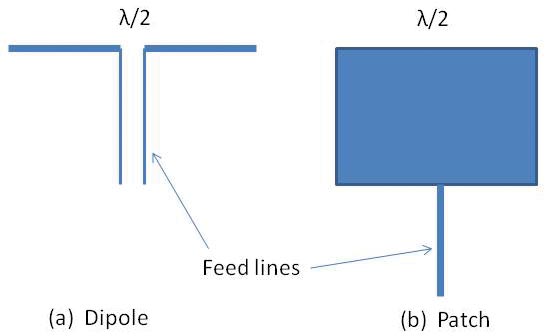
FIGURE 1. Common antenna types: (a) half wave dipole; (b) patch.
The dipole is a basic half wavelength conductor fed at the center. A patch is usually a half wavelength copper square on a PCB. Other antenna types have been used. The spacing between the antenna elements varies with the design but is generally a little more or less than a half wavelength.
Remember the relationship between frequency (f) and wavelength (λ):
f = 300/λ
λ = 300/f
Here, λ is in meters and f is in MHz.
For example, a frequency of 1,296 MHz has a wavelength of:
λ = 300/1296 = 0.23 meters or 23 cm
A half wavelength is:
λ/2 = 11.5 cm or about 4.5 inches
(NOTE: There are 2.54 cm per inch.)
Also keep in mind that the length of an antenna depends on the frequency of operation. A half wavelength is generally computed with the expression:
L = 492/f
where f is the frequency in MHz and the length L is in feet. This formula can also be used where L is in meters:
λ = 150/f
The higher the frequency, the smaller the antenna. At the lower frequencies, the antennas are just too large to be practical. For example, at 30 MHz, a half wavelength is about 16.4 feet long. A multiple array would be enormous. However, at 5 GHz or 5,000 MHz, a half wavelength is only:
λ/2 = 150/5000 = 0.03 meters or 1.18 inches
Bigger arrays at the higher frequencies are smaller and more practical.
Many of the new 5G cellular systems will operate in the millimeter wave bands; 28 GHz is an example. One half wavelength at this frequency is only:
λ/2 = 150/28000 = 0.00536 meters or 0.21 inches
A half wavelength at 60 GHz (a popular unlicensed frequency band) is only:
λ/2 = 150/60000 = 0.0025 meters or roughly 0.1 inches
At these frequencies, large arrays can be packaged in a small space. The antenna array may even be small enough to integrate on a semiconductor chip along with the related circuitry. This translates into phased arrays inside smartphones and other portable equipment.
Figure 2a shows the radiation pattern of a basic dipole. Its figure 8 pattern causes most power to be radiated broadside from the antenna element and also some in other directions, except in those directions at the ends of the antenna elements. By using multiple antennas in an array, the radiation pattern can be shaped into a narrower beam as shown in Figure 2b. This pattern or lobe is made up of multiple signals from multiple antennas in the array. The signals are focused, making them stronger and allowing the beam to be pointed in a desired direction.
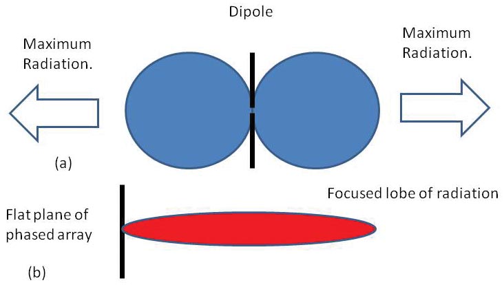
FIGURE 2. The radiation patterns of a dipole (a) and a patch (b).
Phased Array Defined
A phased array is two or more antennas used together to provide some desired characteristic or feature not available with a single antenna. An array is usually a collection of multiple antennas arranged in a matrix of rows and columns or some other pattern.
Figure 3 shows an example using 16 square patch antennas on a PCB. The antennas in the matrix are individually fed units, but collectively they work together as a single antenna. The backside of the PCB has a copper backplane that acts as a reflector. Feed lines are not shown.
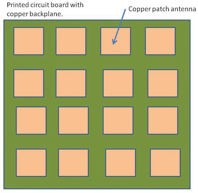
FIGURE 3. A 16-patch array on a PCB. The back of the board is a solid copper backplane that serves as a reflector. Feed lines are not shown.
The whole idea of the phased array is to achieve some needed features. These key features are:
- Gain — Gain is like amplification. Some types of antennas boost the signal level or effective radiated power (ERP) as if greater signal power is used. Gain applies to both transmitting and receiving.
- Directivity — Directivity implies that the antenna is more effective in one direction or another. Directivity means that the signal is narrowly focused in one direction. This focusing of the signal is what creates the antenna gain. Figure 2 showed the broad radiation pattern of a standard dipole and the radiation pattern (or lobe) of a phased array.
- Interference Minimization — Pointing the antenna in a particular direction means that it’s less effective in the other directions. This feature helps eliminate or reduce interference for signals coming in from other directions. Nulls can be created to take out undesirable signals.
- Steerable — Phased arrays can be adjusted to reposition a lobe on-the-fly. The direction of the signal can be changed electronically to optimize the gain. This allows them to scan horizontally and/or vertically.
Phased Array Operation
Phased arrays implement what we call beamforming. This is done by taking the radiation patterns of each of the antennas in the array and adding them together in such a way that they concentrate the energy into a narrow beam or lobe. The individual antenna signals are said to be interfering with one another either constructively or destructively. Some signals combine to form a stronger composite signal, while others partially cancel one another out.
The radio signal to be transmitted is a sine wave. When you algebraically add two sine waves of the same frequency but different phases, you get another sine wave of the same frequency but with a different amplitude and phase. By manipulating the phase and amplitude of the signal at each antenna, the composite beam can be varied in both width and length (power level). Plus, the beam can be steered to point in a desired direction.
There are several ways to implement the phased array. The older analog method is shown in Figure 4. The RF signal from the transmitter power amplifier (PA) is sent to a power divider that splits the RF into equal amounts of signal, creating multiple paths to the antennas. The signals pass through attenuators and phase shifters that allow individual adjustment of the signal level and phase to each antenna element.
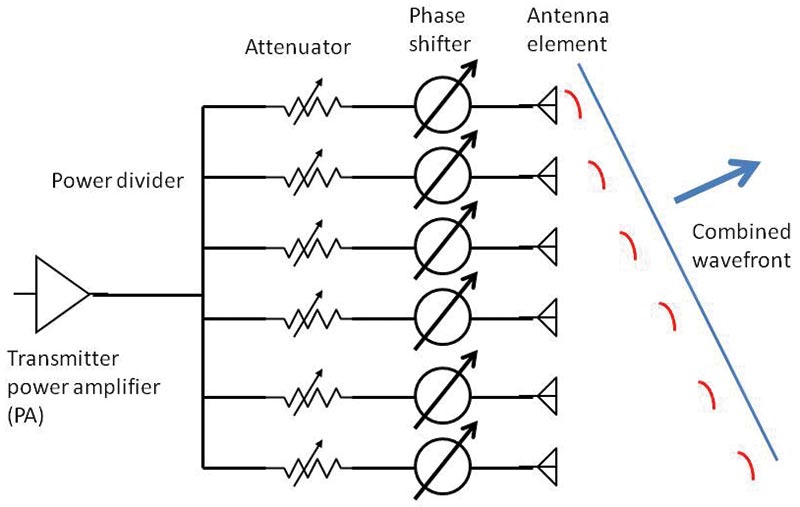
FIGURE 4. An original approach to implementing an array with separate circuits. The phase increments are selected to create a lobe of a desired width and point in a desired direction..
Phase shifters introduce a short delay that can be varied. These phase shifters and attenuators can be adjusted electronically so that changes can be made quickly as needed.
Figure 4 shows how the phase shifters influence the composite signal. The red curve represents the wave front from each antenna. With no delay on the top antenna and equal incremental delays on the lower elements, you can see that the delayed waves occur further out in time to the right. Then, they combine to create a composite wave front that is shifted upward at an angle.
This older method used separate attenuators, phase shifters, and other components. A newer approach is modular. That is, the antenna element and related transmit and receive amplifiers, shifters, attenuators, and switches are packaged together as a module; refer to Figure 5. In transmit mode, the signal from the transceiver passes through the attenuator, phase shifter, and T/R switch to the power amplifier and then to the antenna.
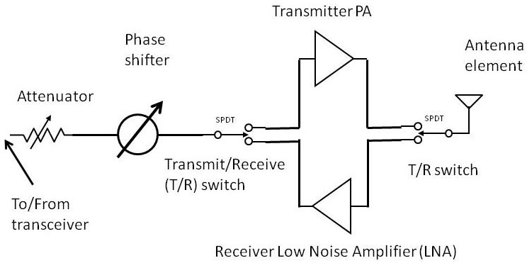
FIGURE 5. The modular approach to building phased array packages with all components on a single chip. The attenuators and phase shifters are electronically changed by an external microcontroller that is programmed to implement a desired beam width and direction.
In receive mode, the signal from the antenna passes through the T/R switch to the low noise amplifier and through the phase shifter and attenuator to the receiver section of the transceiver.
These modules can be packaged together as an array as needed. Today, semiconductor technology lets you put one or more modules on a single semiconductor chip.
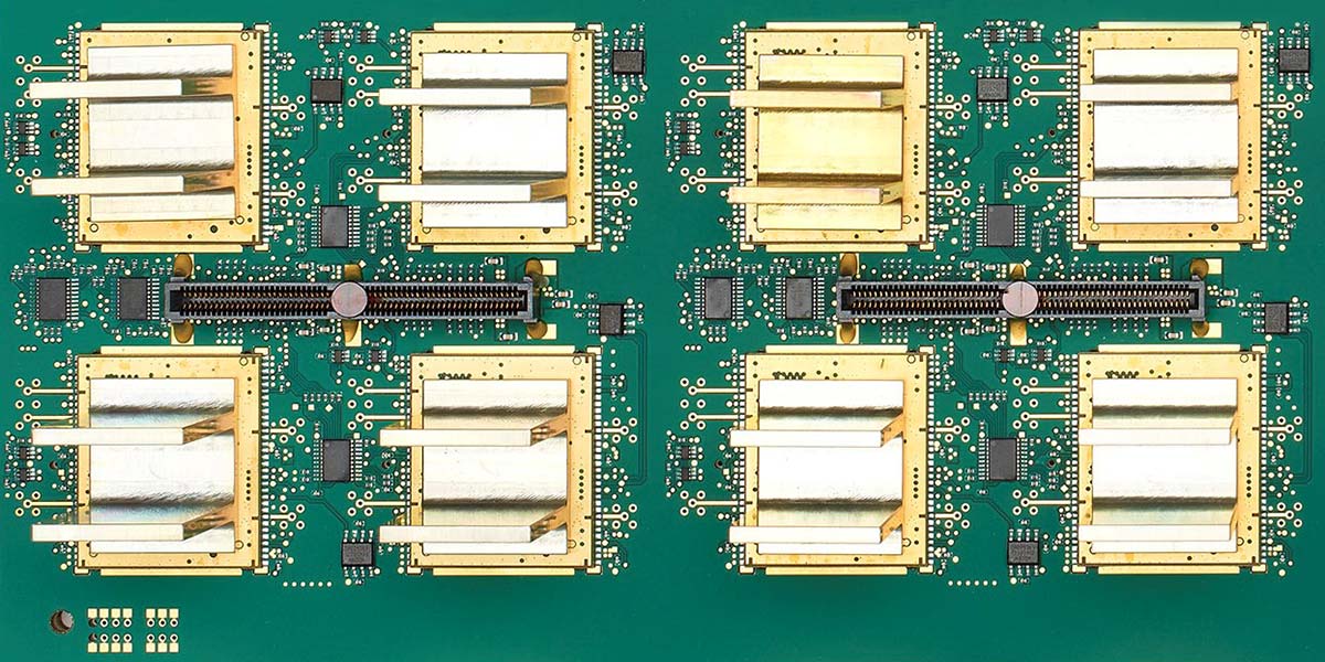
A good example of a commercial product available to implement phased arrays is the Anokiwave family of millimeter wave phased array front-ends. The AWMF-0139 operates in the 24 to 26 GHz band allocated to the coming 5G cellular networks. It encapsulates four modules per IC. Figure 6 shows how 64 of these chips can be used to make a 4 x 64 = 256 element array. Another similar IC is Analog Devices ADAR1000.
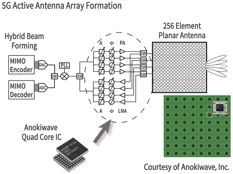
FIGURE 6. The Anokiwave AWMF-0139 IC contains four antenna modules. These ICs are mounted on the back of the PCB with the patch array on the front.
MIMO
Phased array antennas can also be used for multiple input multiple output (MIMO). MIMO is a technique that transmits the same data with multiple antennas over the same path in the same bandwidth. This does two things.
First, each signal takes a slightly different route to the receiving antennas. The result is less fading and greater data reliability. Second, MIMO multiplies the data rate by a factor that is determined by the number of transmit and receive antennas. Common configurations are 2 x 2, 4 x 2, 4 x 4, and 8 x 8, where the first number is the number of transmit antennas and the second number is the number of receive antennas.
A multi-element phased array can be partitioned into sections making it suitable for some MIMO applications. For example, the 256-element array could be arranged to provide four 64-element arrays or sixteen 16-element arrays. With beam steering capability, the signal path can be optimized for best performance.
Also, 5G cellular radios operating in the millimeter wave bands will use MIMO to give gigabit data rates. The big hurdle is putting a phased array into a smartphone handset. Initially, two antennas will be used and later will be increased to four. MIMO is also widely used in Wi-Fi routers. NV