Some people tend to shy away from using surface-mount components in their projects. It seems to be too difficult or needs an array of specialized equipment. In the past, I found myself in this same mindset — wary of using these types of parts. That all changed when I got involved with an open source motor controller project (OSMC).
It used a mix of surface-mount and through-hole components. I took the plunge and built up a pair of OSMC H-bridge boards and the MOB (Modular OSMC Brain) controller board which I used in the Battlebot Crash Test Junior.
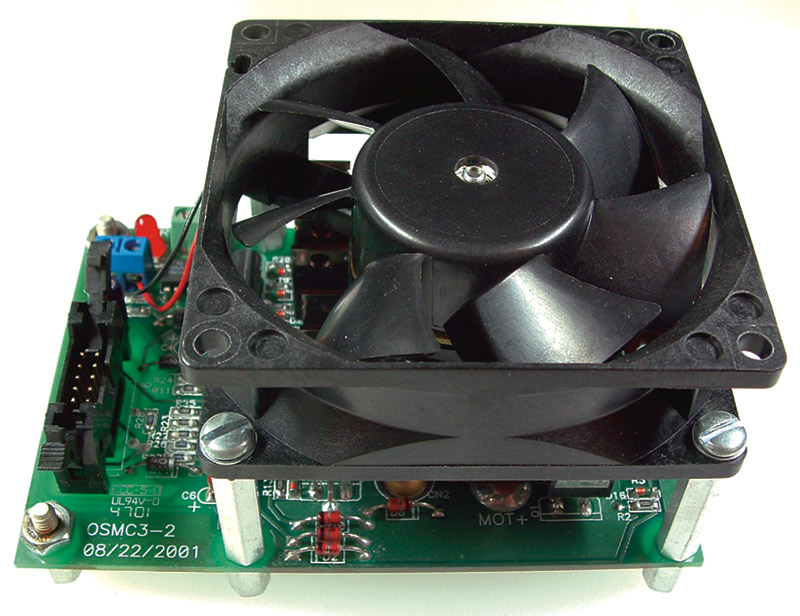
An OSMC H-bridge board.
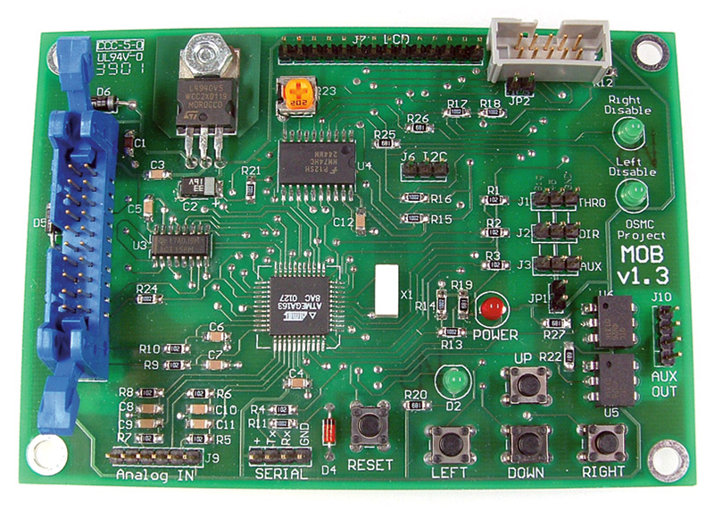
MOB controller for OSMC boards (example of surface-mount and through-hole parts).
At the time, there was little information available on how to mount these parts using an ordinary soldering station and tools that most hobbyists would have on hand. Not wanting to invest in a whole new set of tools (hot air stations, etc.), I experimented a bit and used common sense techniques to get the job done. A point I'd like to stress is the myth about requiring anything exotic to work with most surface-mount parts. I don't own or use any special soldering equipment for this. All of the soldering that I've done on surface-mount boards is built with an old Weller WTCPT station and TC201 soldering iron. It has the fine tip that came standard on it. If you happen to have access to specialized tools, go ahead and use them but you still may find these tips helpful. It has been my experience that depending upon your techniques, you can get by just fine in most instances without specialized tools.
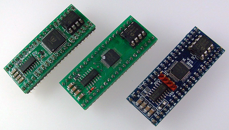
Small hybrid modules assembled with ordinary soldering gear.
The techniques and methodology you use when initially assembling a project using surface-mount parts can make all the difference! It takes a little getting used to but quickly becomes second nature. It does require good eyesight (or a big magnifying glass) and a steady hand though. Now, if you start talking about parts that use a ball grid array (BGA) connection or others like that then you would need special tools. Careful selection of parts to avoid difficult package styles can make using tools most people already have on their bench a viable option.
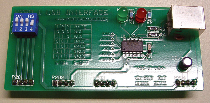
A USB interface for my HERO 1 robot (surface-mount and through-hole parts).
Figuring Out How To Use Existing Tools
Surface-mount parts can be soldered with traditional hobbyist soldering equipment. Some of the construction methods are very similar to traditional methods but are a bit more delicate. Tools and supplies you should have on hand are:
- Soldering iron (pencil type) with fine tip
- Needle nose pliers
- Diagonal cutter
- Tweezers
- Vise (or something similar to hold a PCB)
- X-acto (or utility blade)
- Good quality solder (60/40 rosin core preferred); RoHS can be used
- Solder wick
- Liquid/paste solder flux (no acid flux or solder paste!)
- Magnifying glass
- De-fluxing spray (or rubbing alcohol)
- Cotton swaps
NOTE: You'll find that the results tend to be better with standard tin/lead based solder instead of the newer RoHS formulas. The RoHS based solder seems to do well with small caps and resistors, but the lead based solder is still easier to work with. It just seems to flow better and provides a much nicer looking solder connection. The RoHS solder ends up looking like a cold solder joint even when it is actually okay.
Parts Suitable For Soldering With Standard Equipment
Most surface-mount parts can be used with standard soldering equipment, but there are a few exceptions. Parts that come in a BGA or QFN (quad flat no leads) package have pads underneath the part which make them almost impossible to solder without using an oven. Other package styles like the SSOP, QFP (quad flat pack), TQFP, TSOP, SOIC (small outline IC), or SOT (small outline transistor) have exposed leads that can be easily soldered. (There is a link at the end of the article to Wikipedia that has a nice description of each package style.) Standard chip capacitors and resistors which just have a single connection on each exposed end are probably the easiest of all to work with. As long as you can get to the leads with the tip of the iron, you should be able to solder them.
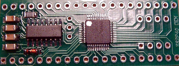
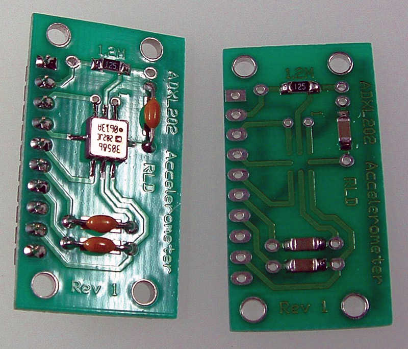
Top of PCB using surface-mount parts.
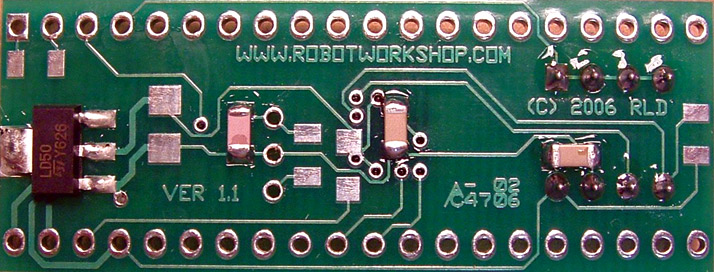
Bottom of PCB using surface-mount parts.
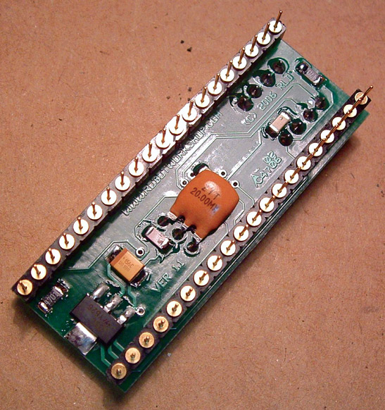
Bottom of finished PCB using surface-mount parts.
How small is too small? When building with surface-mount parts, about the smallest I work with are the 1206 capacitors and resistors. I have used some of the tiny 0603 parts, but they are hard to hold onto. It felt like I was trying to build a ship in a bottle. It was necessary to have a few spares on hand, because if one was dropped it was gone, never to be seen again. They are quite difficult to pick up, so I only use ones that little if I really have to.
It’s All In The Technique
You don't need any previous surface-mount experience and as long as you are adept at soldering you can learn to work with these parts. There are a couple different methods that can work well for hobbyists. One uses a hacked toaster oven to solder the boards. The oven method uses solder paste which goes on all the pads and contains both solder and paste to hold the parts in place. The parts are then set into the solder paste and a hacked toaster oven heats the whole thing to solder them. I've never used that method, so I won't focus any more on that here. For those interested in using an oven, there are links at the end of the article to more detailed information online.
There was also an article way back in the June 2003 Nuts & Volts which specifically covers modifying a toaster oven for this exact purpose.
The other method uses a regular soldering iron and is what we'll focus on here. There are two slightly different variations to this method which both provide excellent results. The first only applies if the PCB (printed circuit board) was made with a reflow solder finish. (This is where the board already has a thin layer of solder applied by the PCB manufacturer on the pads.) In this case, you just need to heat each pin and pad so that the solder from the pad will stick to the lead of the part. When using this method, you should have a nicely tinned tip (important for heat transfer) but not any excess solder. I usually only use this when installing very fine pitch parts like the TQFP devices. If the board doesn't have any extra solder, then you'll have to do more traditional soldering.
NOTE: During assembly, make sure you keep the soldering iron tip clean. Wipe it often on a wet sponge or cloth then apply a little solder to the tip. This will protect the tip and enable you to make good connections. When the solder tends to "ball" or does not stick to the tip, the tip needs to be cleaned and re-tinned.
Do not rush! After perfecting the techniques, you'll naturally get faster along the way. A good surface-mount solder connection forms the electrical connection between two parts, such as a component lead and a circuit board foil. With surface-mount parts, it also provides the mechanical connection, as well. Make sure there is enough solder to leave a nice fillet between the component lead and the pad.
NOTE: Before installing any components, plan ahead and think about the final placement of each part and what the final board will look like. With that in mind, it should help with the assembly order so that each component will not block the next one installed.
The alignment of the parts is critical. Small components like the 1206 capacitors and resistors are more forgiving and are good to start out with. Others like a TQFP microcontroller are absolutely critical in regards to placement with their fine pitch leads. Before installing a surface-mount component, apply a small amount of solder to one (and only one) of the pads on the PCB where the part is going to be installed.
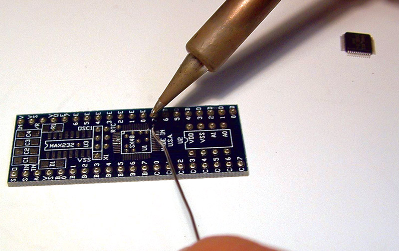
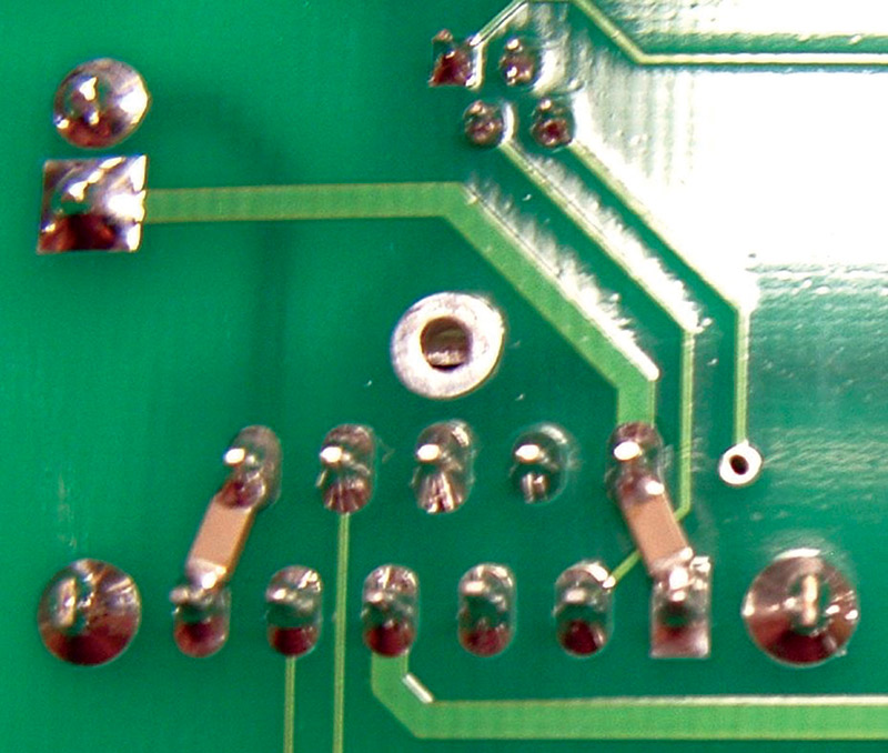
Application of solder to one pad.
Then, while warming the solder on that pad use the tweezers to set the part in place. If the alignment isn't right, you can do adjustments while the solder is still molten. If it takes too long, let the solder cool to ensure the part is not damaged by excessive heat. Once cool, the joint can be warmed up again and the alignment can be adjusted until it is perfect.
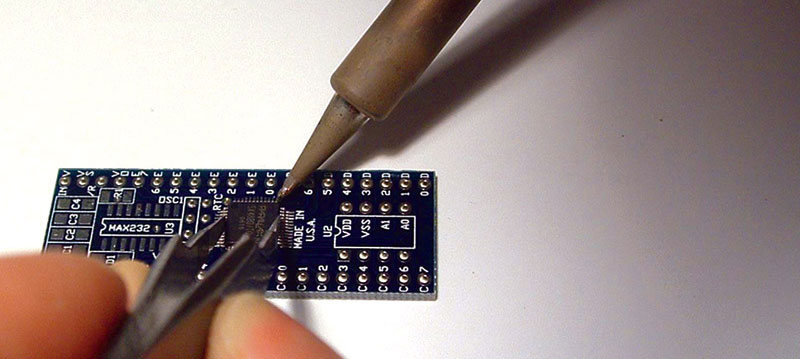
Installation of surface-mount chip.
Before soldering any other joints on the part, use the magnifying glass to verify that the alignment is okay. At the moment, the exact orientation of the part in relation to the pads is what we're concerned with. Next, go ahead and solder an opposing lead on the part. As long as everything looks good, continue soldering each one. I usually go back and re-solder the first pin since it may be messed up from re-positioning the part.
NOTE: Some people prefer to use a small dot of glue to hold each component in place before soldering. If this works out well for you, use that method but keep in mind it adds another step and can make rework more troublesome down the road if you have to replace any parts.
Working with Fine Pitch Parts
Care needs to be taken to ensure that there are no solder bridges causing shorts. When dealing with fine pitch parts, do not be concerned about solder bridges at first. Since the pitch is so close on these pins, just solder each side without worrying about solder bridges and let it cool before going on to the next side. When done, let the whole component cool. Then, go back over each side with solder wick to remove the excess solder. This will remove most of the solder and leave just enough to make a proper connection. Repeat the process if solder bridges still exist.
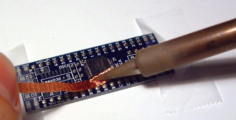
Removal of excess solder.
Solder wick is your friend when working with surface-mount parts. If you ever get a bridge or too much solder on a connection, just use the wick to remove the excess. In the event you remove too much, you can always add more solder and repeat the process. Be sure to let the component cool between each side so the part will not be damaged by excessive heat. The results can be fantastic if you take your time.
Replacing Surface-Mount Parts
Sometimes you may need to replace a surface-mount component. There is one method I have found works very well for fine pitch parts. I use a sharp utility knife to cut the leads right at the body of the part. It requires a steady hand since you only want to sever the lead without nicking the PCB. That may not be a problem if there are no traces underneath the chip but it is always best to assume there are and be very careful during the process. When I was removing an SX28 processor, the leads were thin so I only needed to cut one side and then bend the chip up and down to break off the other side. With the chip out of the way, the rest of the preparation was easy.
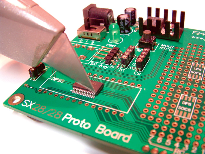
One method of removing a chip.
A chip once cut for removal.
Just put a fresh bead of solder down with the iron and all the leads end up sticking to the soldering iron. Just wipe them off on your sponge. The last step is to go over the pads with solder wick so they are all flat again, ready for the installation of the new chip.
Other Uses For Surface-Mount Parts
Some surface-mount parts are particularly useful for making corrections and upgrades to existing circuits and during prototyping. Since they are small, you can easily use 1206 resistors as pull-up resistors or even use the small caps between existing pins for improved filtering. They can really help. Since they mount on the surface-of the board, you can use them on either side which opens up more options.
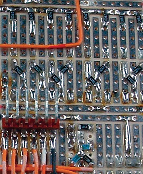
Surface-mount resistors between pads on a protoboard.
Adding extra capacitors between pins.
Conclusion
Hopefully, this has provided a good oveview of how you can assemble boards that have surface-mount components using many of the tools you already have on hand. You can do it! Just start with some of the surface-mount caps and resistors in the 1206 package style. That way, you can start with some of the easier parts and get confidence up. Once you get used to them, you can try other components with fine pitch leads. If you lay out your own boards, you can easily place 1206 pads right along with the pads for through-hole components so that either style can be used.
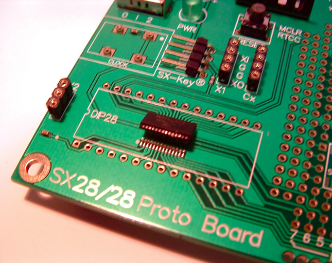
Boards with pads to accept surface-mount or through-hole parts.
I've found that some simple parts like the surface-mount caps and resistors can be installed faster than their through-hole companions and can reduce the time to build a project. They can also help reduce the size and weight of your project. Overall, learning surface-mount skills can be quite rewarding and I hope that those of you making the attempt will enjoy the process and perhaps learn a few new techniques. Once you start getting used to surface -ount parts, they are not that hard to work with. NV
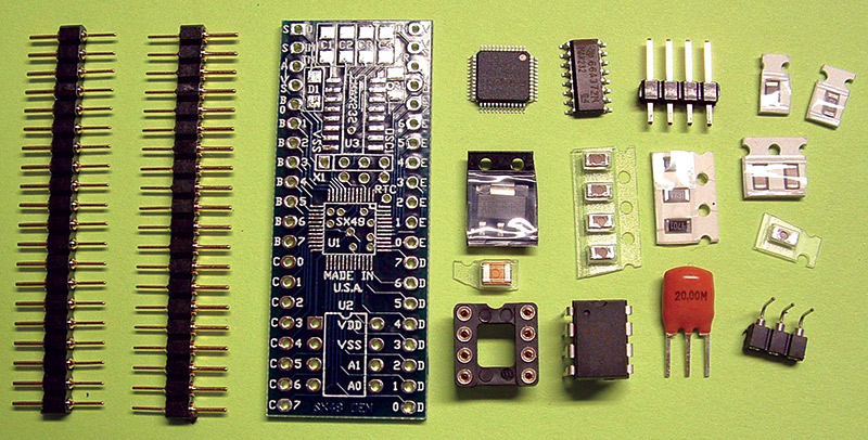
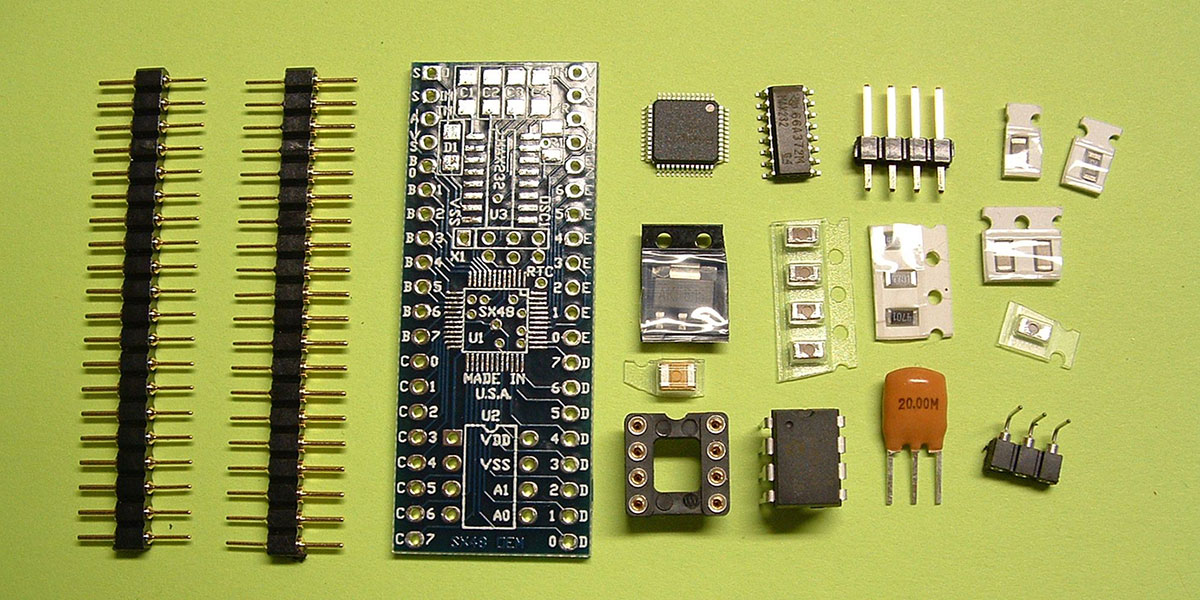
A surface-mount kit.
WEBSITE REFERENCES
Robot Workshop (author’s website).
www.robotworkshop.com
Tutorials about surface-mount soldering from SparkFun.
www.sparkfun.com/commerce/tutorials.php
Wikipedia article on surface-mount.
http://en.wikipedia.org/wiki/Surface-mount_technology
Intel information about surface-mount technology.
www.intel.com/design/packtech/packbook.htm
Surface-mount tutorial.
www.tutorialsweb.com/smt/smt.htm
Excellent book on using surface-mount components:
Surface-Mount Technology for PC Boards
By James K. Hollomon, Jr.
Prompt Publications ISBN 0-7906-1060-4