Many times during my illustrious career as an electronic hobbyist, I have designed devices that incorporated op-amps. As these projects usually operated from a transformer/rectifier type power supply, I would design the supply to produce both positive and negative voltages which would satisfy the op-amp. Nowadays, as it seems everything is battery operated, I find myself designing stuff around that very popular “nine volt battery” and more recently around five volt USB power.
Question: How does one connect a single polarity voltage source to an op-amp that wants to see both a positive and a negative voltage supply?
While it is true that some op-amps such as the LM324 are designed to work with a single positive voltage source, they still won’t handle ground referenced AC signals. (By the way, all the circuits shown assume the use of the LM324 op-amps or equivalent.) However, as noted, other types can be considered. Those “other types” will include the newer low power, low voltage, rail-to-rail jobs powered only by the five volt computer supply.
Here is a fact: Op-amps that are expected to handle ground referenced AC signals in a linear manner must see a negative supply voltage in respect to their input pins. This configuration sets both the input and the output points to average ground. Only in this way can the output swing an AC signal both positive and negative in respect to the general circuit ground. Here is a problem: Connecting an op-amp to a single positive polarity supply does not allow the output to swing in a negative direction. In this case, a nice looking sine wave at the input will look like a half wave rectified signal at the output. Solution: Trick the op-amp into thinking it has a negative voltage supply. Here are some ways this can be done.
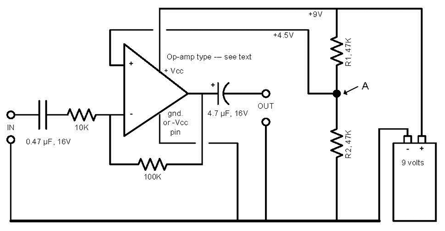 |
| FIGURE 1. This is the inverting version. The large DC offset makes coupling capacitors a must. Point “A” will feed additional op-amps. As shown, the amplifier will produce a voltage gain of 10 (inverted). |
The “trick” is to elevate the input pins to half the supply voltage. This is accomplished by means of resistors R1 and R2 as shown in Figure 1. This, in effect, makes the normal ground pin look 4.5 volts negative in respect to its input circuitry. Our op-amp now has its negative supply and is happy. As shown, the circuit has an input impedance of 10K ohms and will produce a voltage gain of 10 (inverted).
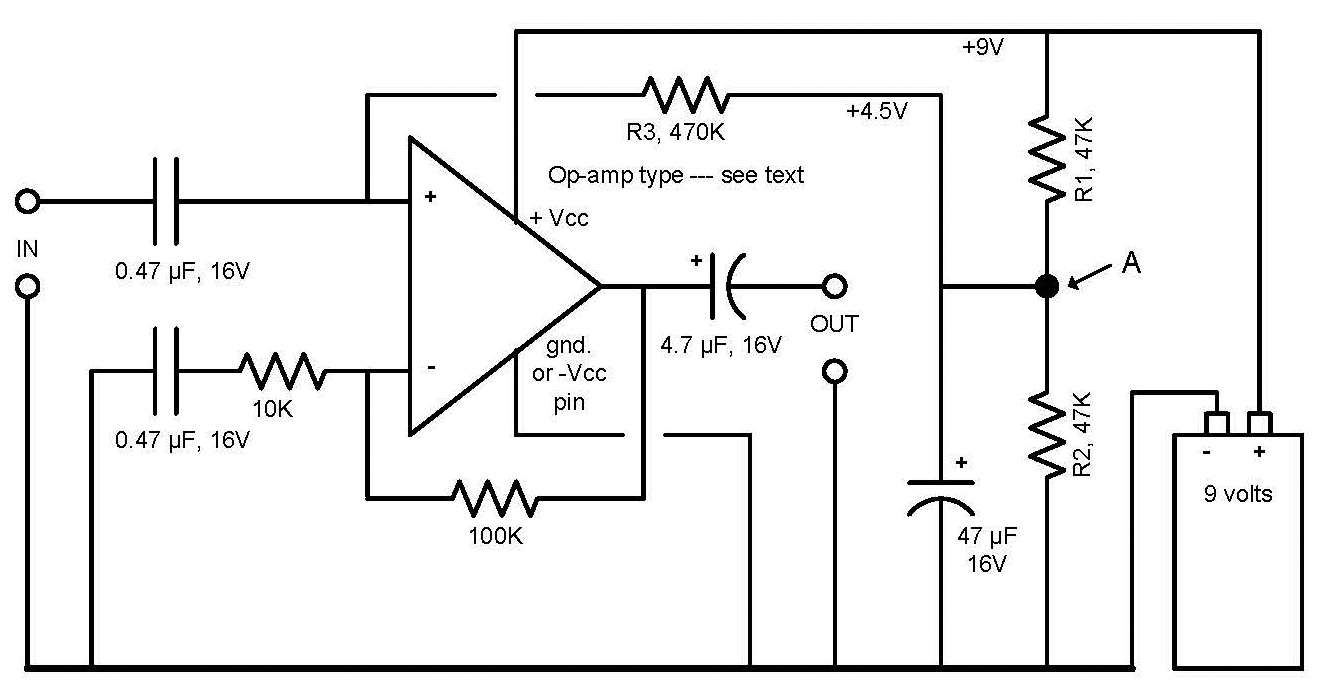 |
| FIGURE 2. This non-inverting version requires a few more components than does the inverting version shown in figure 1. Point “A” will feed several more op-amps, but don’t forget additional “R3”s. As shown, the amplifier will produce a voltage gain of 11. |
Let us consider what might be called a downside to this configuration. Note that because both the input and output points have an average +4.5 volts stuck to them, coupling capacitors are needed to block this voltage from reaching associated circuitry. The value of these capacitors will have to be calculated so as to assure that the lowest frequency of interest will be passed on to the next device. Some typical values are shown. Now consider Figure 2. This is similar to Figure 1 except that this configuration does not invert the input signal polarity, which might suit your needs better. Note that an additional coupling capacitor at the “+” input, as well as a few other parts, are needed. As shown, the circuit has an input impedance of 470K ohms and a voltage gain of 11.
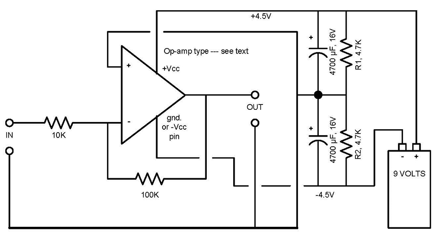 |
| FIGURE 3. This version features ground referenced input / output and DC coupling. As shown, the amplifier will produce a voltage gain of 10 (inverted). |
Figure 3 shows another way to make the op-amp see a dual polarity supply. This configuration has an advantage in that there is no 4.5 volt offset which eliminates the need for input and output coupling capacitors. AC output signals can swing both positive and negative in respect to circuit ground, and input/output points are ground referenced which makes interfacing easier. Obvious, too, is that AC signals will respond all the way down to DC.
The trick here is similar to the circuits just described in that two equal value resistors are used to split both the battery voltage and polarity. To analyze this, consider that using their junction as a reference, the positive battery terminal will measure +4.5 volts and the negative terminal will measure -4.5 volts. As this junction becomes the common ground point, our op-amp sees a dual polarity supply. It’s a sort-of pseudo center-tap for an otherwise floating voltage source. The rather large capacitors across each resistor assure that the voltages will be stable when non-sinusoidal waveforms are present. As shown, this configuration has an input impedance of 10K and a voltage gain of 10 (inverted). Figure 4 shows virtually the same circuit but configured as a non-inverting amplifier. In this case, the input impedance is equal to whatever resistor you choose to use at the “+” input pin, and voltage gain is 11. Note: If you plan to use this configuration as a DC amplifier, output load currents must be kept to less than one milliamp. Currents greater than this will upset the DC polarity balance and produce gain errors.
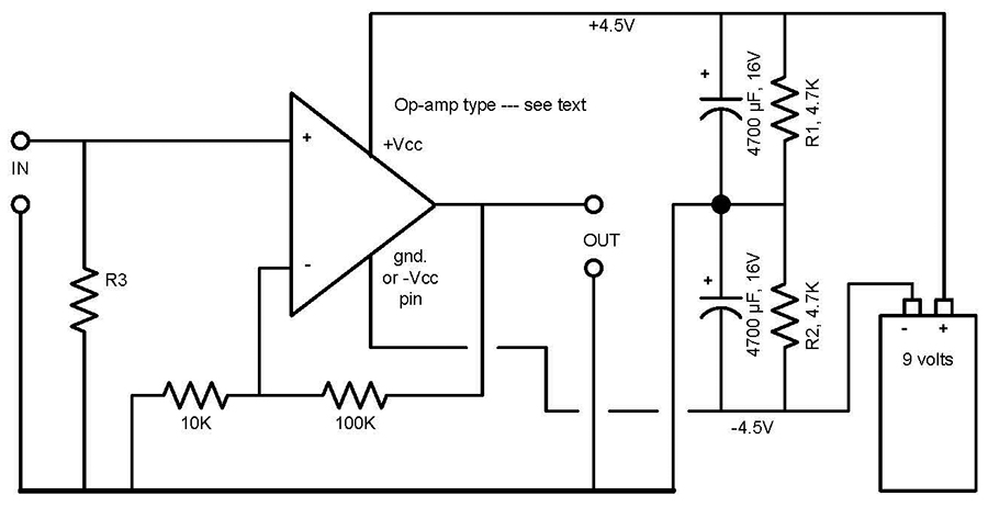 |
| FIGURE 4. This non-inverting version features input impedance equal to R3 selected. As shown, the amplifier will produce a voltage gain of 11. |
A few words about maximum peak-to-peak output voltage: Theoretically, an op-amp powered with a nine volt battery should output 9V P-P. In actual practice, the figure will be somewhat less simply due to its internal design. Bi-FET type op-amps are the poorest performers in this respect, however low power versions such as the TLO64 do somewhat better. The best performer is the already mentioned LM324. It works very well on nine volts, draws little current, and its output can swing just short of the total supply voltage. Even with these peak-to-peak voltage limitations, most designs can be made to work well with these levels. If your design requires the greatest P-P level possible from your existing supply — whether it be nine volts or five volts from a logic supply — you will want to use the newer low power rail-to-rail jobs. These are designed to work well on five volts — even less — and can swing the full power supply voltage, whatever it is.
CAUTION: If you plan to use these R-R devices on say nine volts or more, check the datasheets as some of these are only rated for a little over five volts. The configurations shown in Figures 1 and 2 would likely be the ones to use with a five volt supply and a R-R op-amp. Be sure to use all of the components shown, minus the battery, of course.
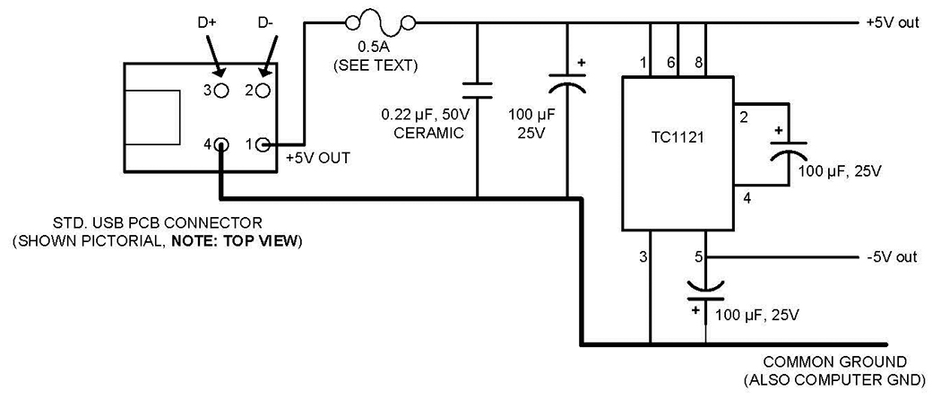 |
| FIGURE 5. USB powered dual polarity supply that will provide up to 100mA. It allows for the conventional +/- op-amp power connections. |
For those of you that are marrying your analog circuits to a computer, you may want to consider the USB supply shown in Figure 5. This a true dual polarity supply with enough muscle to handle large size analog/digital circuits. The positive part of the supply simply uses the existing five volts from the USB port, and the negative part uses “charge pump” technology incorporating an eight pin chip and a few capacitors. This results in a ±5 volt supply that will handle currents up to 100 mA. When powering op-amps with this supply, use the old standard +Vcc/-Vcc hookup. The fuse (as shown) is highly recommended. I use a 0.5A, FB instrument type (which I have popped several times — saving my laptop’s power supply from damage). Let’s keep those op-amps happy! NV