I was bitten by the microcontroller bug a number of years ago and enjoyed building a variety of gadgets that use them. One of the tedious aspects of gadget building is the buttons and switches that make up the input controls. When I discovered the pushbutton rotary encoder, I realized that one control could replace many, simplifying the design, construction, and programming.
This article will introduce you to rotary encoders via the Greyhill 62P22-L41. I will describe what it is, how it works, and how to integrate it into your project. A demonstration will be presented using a PIC16F84A2, along with the project code written in C. (Although the 62P22 is now out of production, similar substitutes can be found including the 62AG22-L5-P panel mounted version.)
The Greyhill 62P22-L4
I chose this device more or less at random, because it was in stock from my favorite supplier.
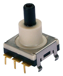
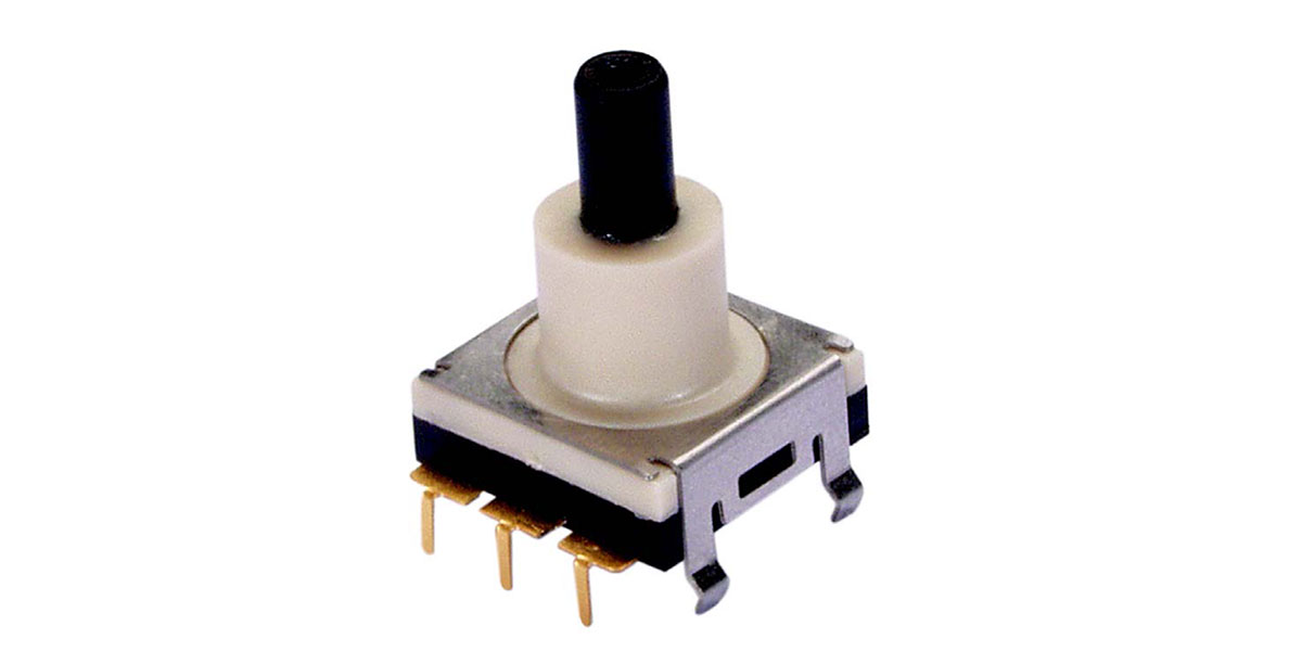
FIGURE 1. The encoder.
The shaft rotates with soft detents, and can be pressed in as a pushbutton. Each detent is at 22º of rotation. There are no stops and no reason why it cannot be rotated endlessly either clockwise or counter-clockwise. This model comes in two different rotational torque and two different pushbutton forces; the L4 model is the lower torque and lower force model. (Other types with a variety of features such as integrated joystick are also available.)
This rotary encoder requires a +5 VDC supply at 30 mA. It uses an internal LED and optical detector to produce its output. The pushbutton is a mechanical contact type and requires a few milliseconds to debounce (four at make and 10 at break3).
The rotary encoder outputs a two bit binary code on its Output A and Output B pins. This gives four unique values, after which the code repeats itself. Once you know the previous and current output values and the code sequence, you can determine which way the shaft has been rotated.
If you assume that Output A is the low order bit and Output B is the high order bit, when rotated clockwise the encoder outputs 0, 1, 3, 2. When rotated counter-clockwise, the output is 0, 2, 3, 1. (There is, of course, no reason why the bit order could not be reversed and the output sequence changed correspondingly.)
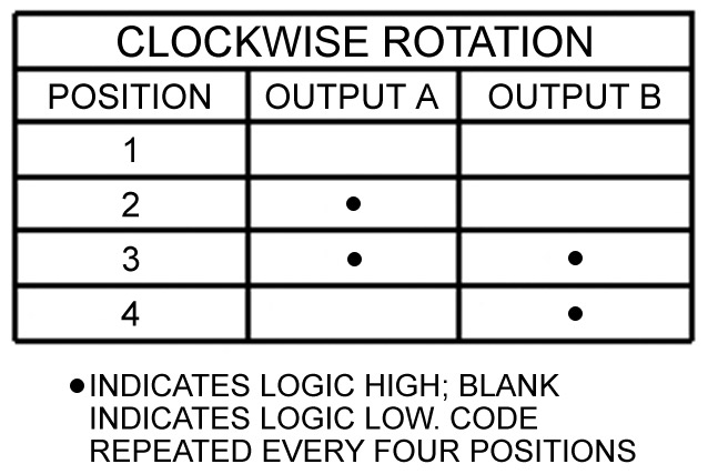
FIGURE 2. Encoder logic states.
To produce a number in the sequence shown, place Outputs A and B in a byte in working storage like this:
| bit 7 |
|
|
|
|
|
|
bit 0 |
| 0 |
0 |
0 |
0 |
0 |
0 |
B |
A |
At startup, the program must read the encoder value, since it could output any of its four values. The value is saved in memory as the previous value. The encoder is then polled until the value changes. Comparing the previous value and current value to the sequence 0, 1, 3, 2, you can tell which way the shaft has been rotated and act accordingly. Then the current value is saved as the previous value and polling continues.
Note that the encoder outputs require pullup resistors. In my demonstration example, I use the internal pullups available at port B of the PIC16F84A for the encoder and the pushbutton. Otherwise, 10K resistors to the +5V supply are recommended.
The pushbutton is debounced and read like any pushbutton. According to the specifications, the longest settle time is 10 milliseconds — which is pretty fast — so your code can be responsive to button presses.
Finally, the encoder supply pin requires a 150 ohm resistor between it and the +5V supply. The encoder’s pinouts are shown in Table 1.
| Pin |
Description |
| 1 |
Supply (+5 VDC through a 150 ohm resistor) |
| 2 |
Ground |
| 3 |
Output B |
| 4 |
Output A |
| 5 |
Pushbutton |
| 6 |
Pushbutton |
TABLE 1.
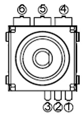
FIGURE 3. Pin numbers viewed from the top.
What Can I Do With It?
The obvious use of the encoder is for the clockwise rotation to signal an “up” type event, the counter-clockwise rotation “down,” and the pushbutton to signal some kind of request or mode selection. For example, let’s say you are designing a programmable thermostat with an LCD readout. You want it to control either a furnace or air conditioner, so it has three states: cool, heat, and off. You could use up and down buttons for the temperature, and a three position switch for the state. Or, you could use an encoder. Rotating the shaft raises or lowers the temperature setting. Pressing the button changes the mode, activating a menu which allows you to select heat, cool, or off (by rotating the shaft). Pressing the button again returns the unit to run mode.
This is a very simple thermostat, but it is now easy to extend the design with more features, taking advantage of the flexibility of the encoder and LCD display. You can add a clock and time of day programs; you can set the clock; you can add a fan on/off function; and so on, without having to add any more hardware to your design.
Another application is a power controller, possibly to control the temperature of a soldering iron. The pulse width modulation feature of many microcontrollers is ideal for power control of a resistive load, with the help of a power MOSFET. The device could have a one or two digit LED display showing the power level, and a rotary encoder to turn the heat up or down. The encoder’s pushbutton could be used as an on/off switch. (In fact, the power would always be on to the microcontroller, but turning the unit off instructs the processor to set the output power level to zero and disable the LED display.)
If you add hardware debouncing to the pushbutton and connect it to an external interrupt pin, a press of the button can be used to put the microcontroller into sleep mode and the interrupt caused by another press used to wake it up. Battery operated applications would benefit from the decreased power consumption when the unit was off.
The Demonstration Project
This simple project uses a PIC16F84A to manage a rotary encoder as input and a single digit LED display and buzzer as output. On power up, ‘0’ is displayed. Rotate the encoder clockwise, and the number is incremented to 9, then back to zero again. Rotate counter-clockwise and the display becomes ‘9’ and decrements down to 0. Pressing the encoder pushbutton makes the buzzer sound.
The rotary encoder S1 is interfaced to U1 with three I/O pins configured as inputs. The port B internal pullups are used for each PORTB input port, so external pullup resistors are not needed. The PIC uses a 3.58 MHz crystal oscillator, but any crystal up to the maximum frequency supported by the PIC is okay, as long as the timer0 interval parameters are adjusted accordingly. J1 is used for in-circuit Flash programming (I use a Pickit24) and is not required for operation. The buzzer and the LED display are connected to the remaining I/O pins configured as outputs. (If you don’t want to bother with a buzzer, just replace it with an LED and 470 ohm limiting resistor.) U2 provides regulated five volts so that a battery or wall wart can be used to power the project.
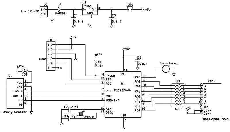
FIGURE 4. Demo project schematic.
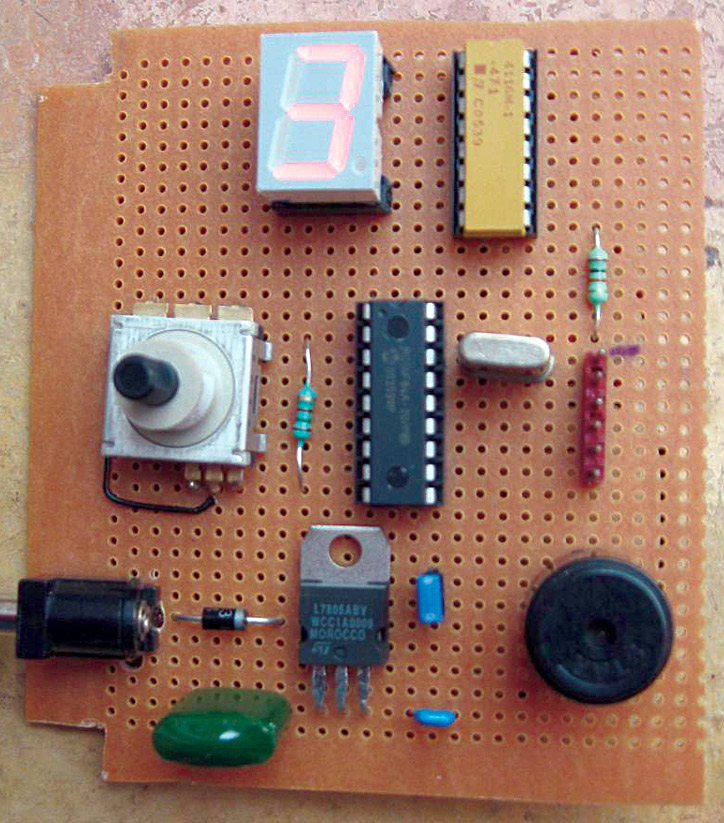
PROJECT TOP.
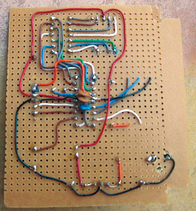
PROJECT BOTTOM.
The Software
The hardware design of microcontroller projects is deceptively simple, because so much of the work is done in the software. Polling for input events is a major task, which must be carefully coordinated with the other work being done by the processor. Improper or poor design may result in input events being missed or responded to sluggishly. The way I manage this problem is to use the PIC’s timer to do all the input polling and switch debouncing. It then posts event flags to the foreground code, which is free to respond to events as they occur.
This architecture works well when an event signals an action that can be processed quickly. I do this for my encoder inputs, where I am incrementing or decrementing the display. Other kinds of events that require time to perform can be more difficult to handle. For my button press, I want to sound the buzzer for a period of time, but I do not want to tie up the main code with a long delay. In this case, the solution is to sound the buzzer in response to the button press, and then schedule an event to turn the buzzer off later (conveniently done in our timer interrupt routine). The benefit is no time-wasting delay loops at all in the program.
To see how the rotary encoder is managed in the software, have a look at encoder_demo.c and encoder_demo.h in the downloads available at the end of this article.
1) In function InitCPU, the option register is loaded to assign the prescaler to timer0 and set the prescaler to 16:1. The timer0 counter TMR0 is initialized to the value in define TIMER0_INIT. Note also that PORTB pull-ups are enabled. Then timer0 and global interrupts are enabled.
2) An interrupt handling function isr (PICC) or interrupt (BoostC) is provided to handle timer0 interrupts. The choice of prescaler and timer0 counter initialization value, along with the crystal frequency, determine the interrupt interval, chosen to be four milliseconds (but not particularly critical for this application). Comments in the code further explain how these values have been derived.
The main activity is to call debounce_switch, the function that polls each input pin and performs the input debouncing. There are no parameters, since global variables in memory are used to manage the debouncing states. If any input level changes, an event flag is set for the main code to deal with.
The secondary activity is to look for the beeper being on, and count down to zero and turn the beeper off.
3) Function debounce_switch polls each input (two encoder and one pushbutton) and keeps track of the state, returning the current state in global variable ucDebouncedState.
4) Function analyze_switch is called by the main code in response to an input changed event. This function determines if the button was pressed or the encoder shaft turned clockwise or counter-clockwise. A corresponding event bit is turned on for the mainline to process.
For the encoder, the method used is to isolate Output A and Output B as the lowest two bits in a byte as described above and see how it compares to the previous value.
Button presses are detected but not button releases. An event for button release could be added if necessary, or a global variable set to 1 when the button was down.
5) The main function looks for the various event flags and performs the required processing.
Conclusion
I hope you found the rotary encoder as interesting as I have. It is easier to design a project to use one in place of a number of other input devices. It is also easier to build a project with one input device instead of many, and the project may be simpler for the user to operate, as well. NV
References
1lgrws01.grayhill.com/web1/images/ProductImages/Opt_Encoder_62P.pdf
2http://ww1.microchip.com/downloads/en/DeviceDoc/35007b.pdf
3www.ganssle.com/debouncing.pdf
4www.microchip.com/stellent/idcplg?IdcService=SS_GET_PAGE&nodeId=1406&dDocName=en023805&redirects=pickit2
Downloads
0808_Botner_encoder-demo-code.zip
What’s in the zip?
Pushbutton Rotary Encoder Demo Code