One of the most important tools any musician needs is a metronome. Its purpose — of course — is to lay down a precise time frame within which a composition will be rehearsed. Yes, accurate tones in pitched music matter tremendously, but so does the timing and pacing of those notes. This is especially true when more than one player gets together.
The earliest metronomes were clockwork mechanisms, but with the advent of solid-state electronics, there are all sorts of new options for units with no moving parts.
The trouble with most DIY affairs that I've seen in the past is that they're based on overly-simple analog circuitry. They almost always drift with time or temperature, and are darn near impossible to calibrate decently. Commercial units may be better in that regard, but often produce cheesy electronic beeping sounds that puts one out of the mood, or aren't loud enough to cut through the din of a practice session.
Enter the Sirius metronome for the serious musician!
This neat circuit sports a number of interesting features that make it a delight to use:
- Exceedingly accurate, both short term and long term.
- Automatic self-calibration.
- One watt internal amplifier is beefy enough for most situations.
- Satisfying natural woodblock effect.
- Different sounds for upbeats and downbeats.
- Line output permits it to be connected to louder external amplifiers.
- MIDI output for even more instrument sounds.
- LCD display with a convenient menu system.
- Visual indication of downbeats (red) and upbeats (green).
- Plus lots of other niceties.
At the heart of it all is the common and inexpensive PIC16F88 microcontroller chip. Before you wince and think this is going to be difficult or expensive to deal with, hold on! The relatively sophisticated firmware is prepared with the excellent and easy-to-use Great Cow Basic compiler. This superior piece of software is free of charge, so there's no reason why you can't customize the metronome to your own liking without breaking the bank.
Let's take a moment to see what the menu structure looks like. This will help you understand the many first-class features available within this unit.
Close-up on the Menus
Our Sirius metronome has four pushbuttons labeled left, right, up, and down. These are used to navigate the menu system. Left and right take you from one menu to the next, while up and down are used to change the pertinent values within each menu. To ease the entry of large numbers, pressing and holding up (for instance) causes the values to increase by tens.
Check out Figure 1 which shows how the menus are organized.
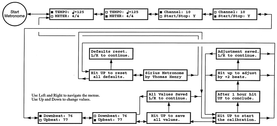
FIGURE 1: Menu structure of the Sirius Metronome.
The firmware to implement this structure is actually a state machine. Once you enter a given state (menu), various options become available until you leave that state. As a consequence, the firmware contains a ton of GOTO statements, but by using Figure 1 as a guide, I had no trouble keeping things straight when composing the code.
You can study it on your own, but let's take a broad look at some of the capabilities. The first two menus let you set the tempo and meter using standard music score notation. Tempo is indicated in quarter notes per minute and may range from 10 (very slow) to 240 (very fast). The numerator and denominator of the meter may be set independently.
The former can span one to nine beats per measure, while the latter may be specified in either quarter notes or eighth notes. While most popular music will perhaps hone in on 4/4 time, the ability to accommodate Brubeck, Mussorgsky, or Stravinsky is definitely there!
The next several menus let you adjust the various MIDI capabilities. This includes setting the MIDI channel that the Sirius will transmit on, whether a synchronizing MIDI start and stop byte should be sent, or MIDI note numbers to be used for the downbeat and upbeat.
Typically, you'll want to connect to a General MIDI (GM) device on Channel 10, since this is where all of the percussion instruments reside. I've defaulted the note numbers to 76 and 77 which correspond to high woodblock and low woodblock sounds, respectively. Remember, there are 40 some other drums you could use; the GM Drums sidebar shows what's available.
GM Drums
The General MIDI protocol allows for many different musical sounds — from orchestral instruments to electronic effects. The percussive instruments are organized within Channel 10. If you're connected to a GM instrument like a synthesizer or even a computer sound card, you may choose any of the following for the downbeat and upbeat sounds.
| 35 Bass Drum 2 |
47 Mid Tom 1 |
59 Ride Cymbal 2 |
71 Short Whistle |
| 36 Bass Drum 1 |
48 High Tom 2 |
60 High Bongo |
72 Long Whistle |
| 37 Side Stick |
49 Crash Cymbal 1 |
61 Low Bongo |
73 Short Guiro |
| 38 Snare Drum 1 |
50 High Tom 1 |
62 Mute High Conga |
74 Long Guiro |
| 39 Hand Clap |
51 Ride Cymbal 1 |
63 Open High Conga |
75 Claves |
| 40 Snare Drum 2 |
52 Chinese Cymbal |
64 Low Conga |
76 High Wood Block |
| 41 Low Tom 2 |
53 Ride Bell |
65 High Timbale |
77 Low Wood Block |
| 42 Closed Hi-hat |
54 Tambourine |
66 Low Timbale |
78 Mute Cuica |
| 43 Low Tom 1 |
55 Splash Cymbal |
67 High Agogo |
79 Open Cuica |
| 44 Pedal Hi-hat |
56 Cowbell |
68 Low Agogo |
80 Mute Triangle |
| 45 Mid Tom 2 |
57 Crash Cymbal 2 |
69 Cabasa |
81 Open Triangle |
| 46 Open Hi-hat |
58 Vibra Slap |
70 Maracas |
|
In the next menu, you have the option of saving any values you've changed so far in non-volatile memory. The next time you power up the unit, you'll resume right from where you left off. This is made possible by dint of the fact the PIC16F88 contains a goodly chunk of EEPROM right within the chip.
Now, the next menu is the coolest of all; this invokes the auto-calibration mode. Upon pressing the up button, the metronome begins playing at its fastest rate. You let it keep playing for exactly one hour, pressing the up button again to conclude. (Use an ordinary clock with a second hand or your computer's clock to tell you when an hour has passed.) After this, the firmware does an internal calculation to determine how many beats — plus or minus — the timebase needs to be corrected for. It stores this correction in non-volatile memory.
Do the auto-calibration several times in a row to attain dead-on accuracy. The first time I ran mine, the timing was under by nearly 500 beats in an hour. The next time it was over by three beats. The third time it was perfect — exactly the correct number of beats in one hour.
Let me emphasize — Sirius does all of the work for you. There is no need to count beats, manipulate numbers, or anything else. The proper correction factor will be computed and stored in EEPROM, and you'll never have to calibrate again.
If, for some reason, you'd like to restore the metronome to its default state, the next menu let's you do so. All of the defaults are reset in the non-volatile memory. It's as though you're turning the unit on for the very first time after construction.
The last menu simply shows an "About" screen, displaying the name of the project and the author. (I always wanted my name in lights!)
We still haven't seen how to start the metronome, so keep moving left or right until you get to the very first menu which shows the meter and tempo. From this state, pressing the left button starts the unit. Press it again and the metronome stops.
Bring on the Digital
Our metronome is a hybrid affair: half digital and half analog. The digital portion appears in the schematic in Figure 2. Refer to it now. As mentioned, the brains of the thing is the PIC16F88 which is a very easy-to-use and forgiving microcontroller. For good accuracy, we'll clock it at 20 MHz using ceramic resonator X1. This connects to pins 15 and 16, with the center pin grounded.
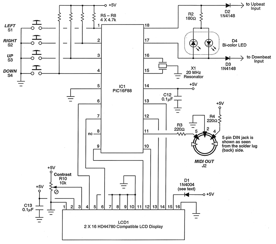
FIGURE 2. The digital portion of the circuit.
The four momentary pushbuttons connect to port inputs A.2 through A.5 (pins 1 through 4). Note the pull-up resistors R5 through R8 which keep the port pins in a known state when no button is pressed. Also observe that the switches have a common ground connection which simplifies the wiring somewhat.
D4 is a two-lead, bi-color LED. When current flows in one direction it shines red; in the other direction, it lights up green. R2 limits the current to a safe value, either forward or backwards. As hinted at earlier, the LED blinks red on the downbeats (start of a measure), then blinks green for the remaining upbeats in the measure. By the way, 180Ω may seem to allow too much current to pass. However, the LED only flashes for 50 mS on each beat so it's perfectly safe to push the limit here, and thus get a nice bright visual indication of your location in a measure.
Since this is a menu-based project, we'll turn to an LCD to provide the human interface. Here we have a typical two line by 16 character display, modeled around the HD44780 controller element. Don't let this gobbledygook put you off; almost all common displays follow this protocol, including the great bulk that you find at surplus houses for peanuts. I wanted something a little fancier for this project and went with a white-on-blue unit I picked up from Amazon.
Now, a word about the backlight on the LCD. These are generally a series-parallel combination of a couple dozen LEDs that light up the display nicely, making it visible in darker surroundings. You will typically need to drop the voltage applied to the anode (at pin 15 of the LCD) by a small amount. Sometimes this is done with a resistor, but the unit I employed specified a rectifier which drops about 0.7V, bringing the current flow down to a safe value. Refer to the spec sheet for whatever you use.
To wrap up this discussion on the LCD, the PIC16F88 provides two control signals (pins 6 and 7 of the PIC) and four data lines (pins 9, 10, 12, and 13). The contrast of the LCD is adjusted by trimmer pot R10.
Great Cow Basic makes it a piece of cake to provide the MIDI output signals using the PIC's internal serial USART (universal synchronous asynchronous receiver transmitter). Trust me, the compiler makes this so easy, you really don't have to know a thing about the messy details. The output appears at pin 11 of the PIC, and R3 and R4 create the usual current loop required by MIDI.
Now for the Analog
Figure 3 shows the analog circuitry needed to get this creature pulsing. Remember, we have two different sounds available: one for a downbeat (higher pitched) and one for the upbeat (lower pitched). Other than the capacitors used to set the pitch, the sub-circuits to generate the woodblock sounds are identical. So, let's focus on the downbeat portion surrounding transistor Q1.
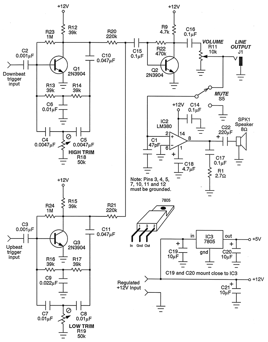
FIGURE 3. The analog portion of the circuit.
At the core of the sound generator is a very high gain filter — almost at the point of self-oscillation. The filter network is the traditional Twin-T configuration. One of the "tees" is comprised of R13, R14, and C6. The other "tee" is made up of C4, C5, and R18. Trimmer R18 brings the filter close to (but not at) the point of oscillation. Thus, the circuit is just sitting there, teetering on the brink of yelping.
When a pulse from the PIC hits it (by way of C2), the system is disturbed and the filter begins to ring, dying off again in a moment. What we've created is a damped sinusoid — a wave that briefly comes on full-tilt, smoothly falling off to silence again. Remarkably, that's what a woodblock does when you strike it with a stick. Thus, we get a nice woody effect that sounds like an acoustic percussive instrument.
If you want to lower the pitch, then increase C4 and C5 (but keep them equal), and let C6 be double that value. The upbeat circuitry behaves similarly. So, feel free to customize the tones of these; the values I've used sound most appropriate to me.
The outputs of both the downbeat and upbeat oscillators are summed by R20 and R21, and sent to a simple preamplifier configured around transistor Q2. This then goes to volume control R11 and then to the line output at jack J1. The signal level is around 1 Vpp, making it suitable for running to an external instrument amplifier if desired.
Otherwise, the wiper of the volume control continues on to the internal amplifier built up around the ubiquitous LM380 chip. Running this chip on a +12V supply and applying it to an 8Ω loudspeaker gives a very usable one watt or so of power.
While IC2 may not be the most distortion-free amplifier chip around, here it works very well. Since we're generating percussive sounds, distortion simply isn't an issue and for all I know may actually improve the replication of a real stick striking wood.
One last thing about IC2. Normally, when using this part at one watt, a heatsink would be required. In fact, I started by using one on the breadboard and couldn't help but note that it was dead cold all the time. That's because the amplifier is responding to percussive signals and is essentially "off" most of the time. So, don't let heat concern you here.
Finally, we come to the power supply. To simplify things, I bought an el-cheapo switching type wall wart off of Amazon for about five bucks. This provides the +12V voltage for the analog portion of the metronome. It also feeds IC3 — the common LM7805 voltage regulator — creating the +5V DC required by the PIC16F88.
Here's an important caveat: Analog ground and digital ground should connect at one point only. This is taken care of by the printed circuit board (PCB) about to be described. Figure 4 shows what the PCB looks like.
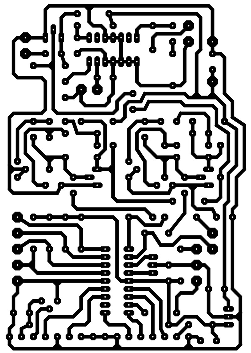
FIGURE 4. Printed circuit board artwork.
Are You Ready To Build?
Despite its potent features, the Sirius metronome is remarkably easy to build. You could make it up on perfboard, as long as you are neat and tidy. Those Twin-T filters are very high gain, so rat's nest wiring is sure to cause headaches. A better approach is to use a PCB.
I whipped up a circuit board in a trice, and it works very well. It's single-sided and sports fairly fat traces, making it a snap to etch at home. A file is provided at the article link. Figure 5 shows the parts placement guide.
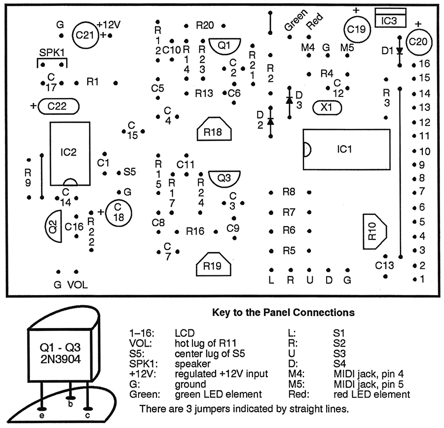
FIGURE 5. Parts placement guide for the PCB.
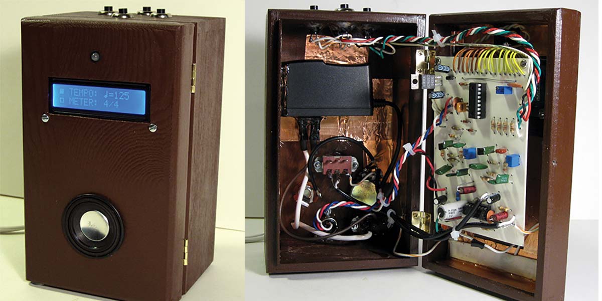
I wanted a metronome that looked sort of "traditional" and decided to go with a wooden box. After cutting the various holes (coping saw, drill, files, etc., required), I then painted the affair a dark brown. I knew ahead of time that hum and noise could be a problem due to the high gain nature of the analog circuitry, so I stuck some copper foil tape strategically around the inside of the cabinet and grounded it.
Being made of copper, I was able to solder a ground wire directly to the tape. If you use aluminum foil, however, then you'll have to screw in a solder lug instead to make electrical contact. In all honesty, I'll tell you right now that if I were doing this again, I'd go with a metal enclosure so I wouldn't have to deal with all that shielding business.
By the way, the PCB pattern provides some extra ground pads to make it easy to run shielded cable to the volume control, line output jack, and mute switch. Figure 6 reveals the innards.
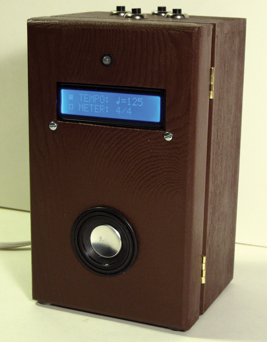
FIGURE 6. Front side of the Sirius Metronome.
I hate wall warts with a passion, so I actually mounted this one internally. You'll notice that I glued it to the inside back with a cement called Goop (available at most hardware stores). I also used Goop — along with lots of heat shrink tubing — to make sure all 110 VAC connections were completely covered; an electrocuted performer can't make much music (except possibly on a harp).
The photograph in Figure 6 shows what the front panel looks like. I deliberately kept it uncomplicated and somewhat Spartan in nature. The speaker, by the way, was a real find. I got it surplus from All Electronics and despite its 1-1/2 inch diameter, it has an amazingly rich sound. Inside a wooden box, it's even better.
Finally, in Figure 7, you'll see what the back looks like. From the top down, you'll spy the mute switch, the volume control, the line out jack, the power switch, the MIDI output jack, and the AC power cord.
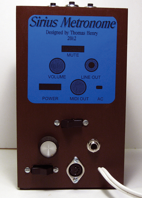
FIGURE 7. Back side of the Sirius Metronome.
About the Code
I could tout the Sirius metronome for pages and pages; there really are some neat things going on here, both from the hardware and software aspects. The source code (available for download from the article link) has been heavily commented and documented, making its study a very practical way to learn the Great Cow Basic language as you build this unit.
If perusing the code, be sure to observe how simple the MIDI interface is thanks to the hSerSend command. There's a lot of action on the LCD, but again, the compiler makes this a snap.
Don't miss the PRINT, CLS, and LOCATE commands; these are pretty much self-explanatory. Also worthy of comment are the custom characters used (the checkboxes and the quarter note icon).
Final Note
Yes, building the Sirius metronome is a great learning experience, but even better, it adds a serious musical weapon to your rehearsal arsenal.
Both your programming and performing chops will benefit, so have at it! NV
Parts List
| Resistors are 1/4 watt, 5% values. |
| R1 |
2.7Ω |
| R2 |
180Ω |
| R3,R4 |
220Ω |
| R5-R9 |
4.7K |
| R10 |
10K Trimmer |
| R11 |
10K Audio Potentionometer |
| R12-R17 |
39K |
| R18,R19 |
50K Trimmer |
| R20,R21 |
220K |
| R22 |
470K |
| R23,R24 |
1M |
| Capacitors are 16V or better. |
| C1 |
47 pF Disc |
| C2,C3 |
0.022 µF Mylar |
| C4,C5 |
0.047 µF Mylar |
| C6-C8 |
0.01 µF Mylar |
| C9 |
0.022 µF Mylar |
| C10,C11 |
0.047 µF Mylar |
| C12-C14 |
0.1 µF Disc |
| C15-C17 |
0.1 µF Mylar |
| C18 |
4.7 µF Electrolytic |
| C19-C21 |
10 µF Electrolytic |
| C22 |
220 µF Electrolytic |
| Semiconductors |
| D1 |
1N4004 Rectifier (see text) |
| D2,D3 |
1N4148 Diode |
| D4 |
Bicolor LED |
| Q1-Q3 |
2N3904 Transistor |
| IC1 |
PIC16F88 |
| IC2 |
LM380 Amplifier |
| IC3 |
7805 +5V Regulator |
| X1 |
20 MHz Ceramic Resonator |
| LCD1 |
2 x 16 LCD Display |
| Other Components |
| J1 |
1/4" OC Phone Jack |
| J2 |
Five-pin DIN Jack |
| S1-S4 |
SPST Pushbutton Switch |
| S5 |
SPDT Toggle Switch |
| SPK1 |
8Ω Loudspeaker |
| Miscellaneous |
| +12V wall wart, circuit board, IC sockets, heatsinks, solder, wire, enclosure, etc. |