Last time, we finished our Fritzing workshops by tying up a few loose ends and then introduced some practical applications with a couple of very useful hardware project kits that will let us easily implement Fritzing designs. We looked at an Arduino proto shield and a breadboard battery that we used with Fritzing to design an Arduino based alarm clock on a mini breadboard. In this installment, we will transfer the components from the mini breadboard to the underlying Arduino PCB prototyping area on the proto shield as shown in Figure 1.
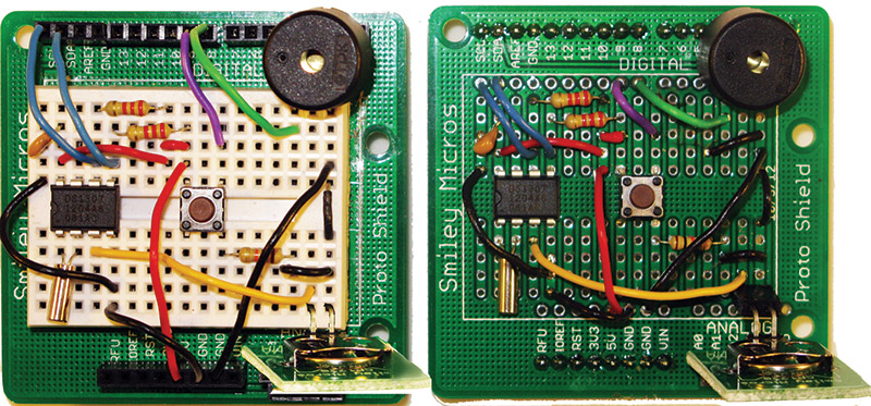
FIGURE 1. Proto shield alarm clock on breadboard and PCB.
This will provide a robust prototype that we will then use to write some alarm clock software that is not only useful in itself, but provides a good basis for more advanced data logging projects. You can get the Arduino proto shield, the breadboard battery, and the alarm clock kit from the Nuts & Volts webstore. But first, we have some great news from Fritzing! They are fixing that bad ol’ parts editor, so let's see what they did, then move on to the proto shield based alarm clock.
Fritzing new parts editor!
The folks at Fritzing just released a new version for their parts editor. If you remember from earlier articles, the old parts editor starts with a warning that it really isn't ready for serious use being a beta and all, but I used it anyway and provided a bunch of examples in earlier articles. Now that stuff is no longer exactly valid. Swell!
You can get some information on this new thing at http://fritzing.org/news/new-parts-editor-released. Who knows, by the time you read this that link may still be valid, but I'd suggest looking around a bit since no telling what may happen between the time my finger hits the keys and the ink dries on the paper.
So, to help keep us up-to-date, I'll discuss how to create a simple part with the new parts editor. First, you'll need to download the newest Fritzing (as of this writing, that’s 0.7). (Update - As of 7/28/16, it's 0.9.3b)
We are going to recreate the breadboard battery part that we discussed in an earlier article. I chose this since I already had the artwork and it only involves two pins. [Also, I upgraded Windows and lost the part in the process — oh well.] To create a part, you start by selecting a pre-existing part such as the generic IC or — as we'll do here — the Mystery Part as shown in Figure 2.
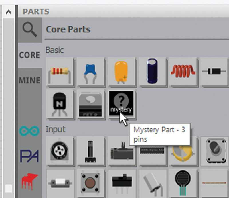
FIGURE 2. Use the Mystery part.
The next step is to set the pin number to 2 as shown in Figure 3.
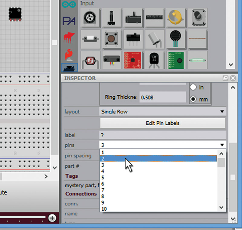
FIGURE 3. Set it to two pins.
Then, right-click on the Mystery Part and click on the "Edit (new parts editor)" as shown in Figure 4.
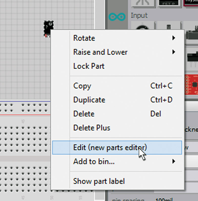
FIGURE 4. Open the new parts editor.
This will open a new window as shown in Figure 5.
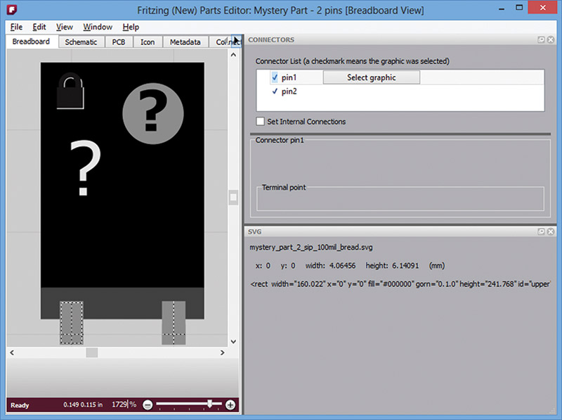
FIGURE 5. The new parts editor.
With the Breadboard tab selected, click on 'File\Load image for view...' as shown in Figure 6.
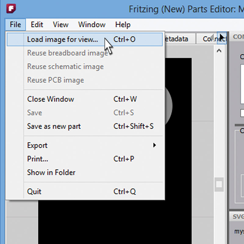
FIGURE 6. Load the breadboard image.
Now, browse to the svg (scaled vector graphics) file that you are going to use. We discussed a little about creating svg files in Inkscape in an earlier article. Unfortunately, you have to modify the svg file, but fortunately the modification is simple.
Open the svg file in a good text editor like Programmer's Notepad, and have it search and delete all occurrences of "px." This is necessary to get the text to show in Fritzing. (Thank you Jonathan Cohen for telling me how to fix this on the Fritzing forum; he says they'll fix it in Fritzing.) Once you make the deletion, you can load the file in Figure 7.
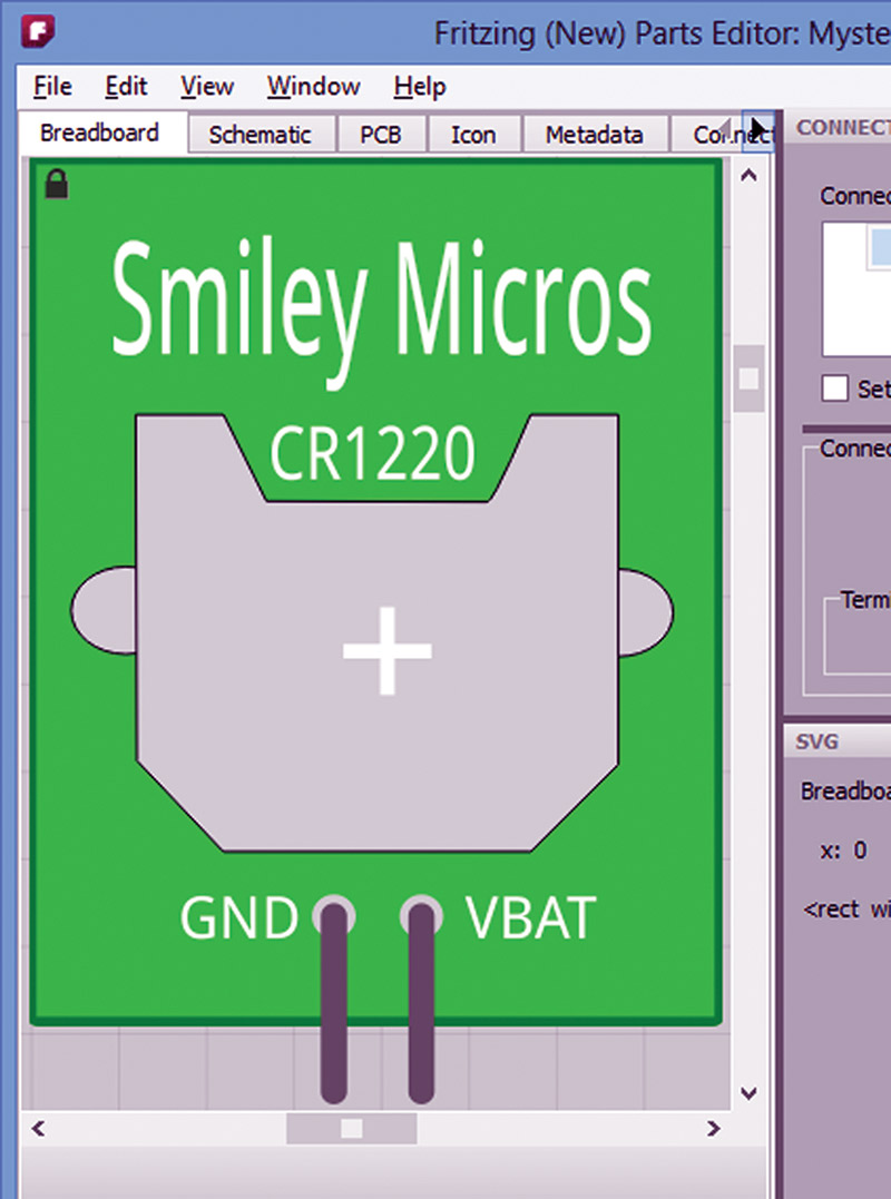
FIGURE 7. The breadboard image.
The schematic drawing is shown in Figure 8.
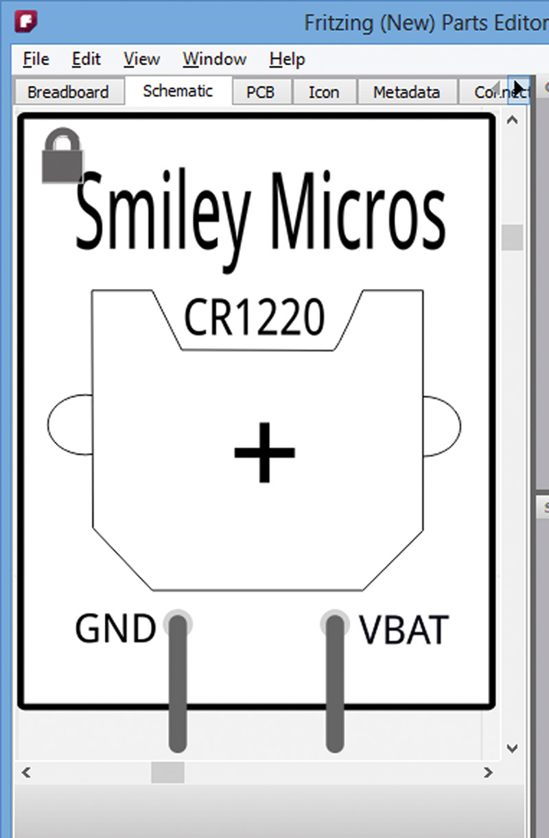
FIGURE 8. The schematic image.
I had to create this drawing from scratch, keeping in mind that the schematic drawings are much bigger than the breadboard drawings. I'm not sure why, but the breadboard drawings have pin spaces as they are in the real world. Thus, the GND and VBAT pins are 0.1" apart, but in the schematics most of the pins are 0.3" apart (meaning that I had to make the schematic image three times larger than the breadboard image).
For the PCB drawing, we will just keep the default image that we inherited from the Mystery Part as shown in Figure 9.
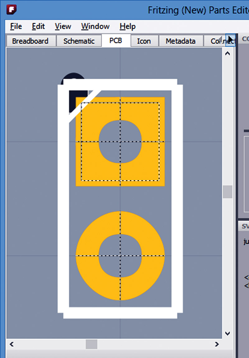
FIGURE 9. The PCB image.
Just keep in mind when you are laying out a PCB that you'll need to allow a full 0.5" width to accommodate the part.
Next, we open the Metadata tab and fill in some relevant information as shown in Figure 10.

FIGURE 10. Metadata.
When you save the part, it will be in your Mine bin. If you highlight it, you can see the metadata shown in Figure 11.
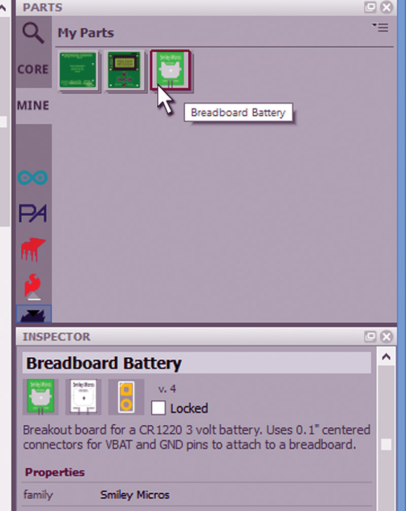
FIGURE 11. Metadata in Inspector.
Now, we go back to the breadboard image and assign the pins. Click on the 'Select graphic' item for the pin and then click on the indicated pin (Figure 12).
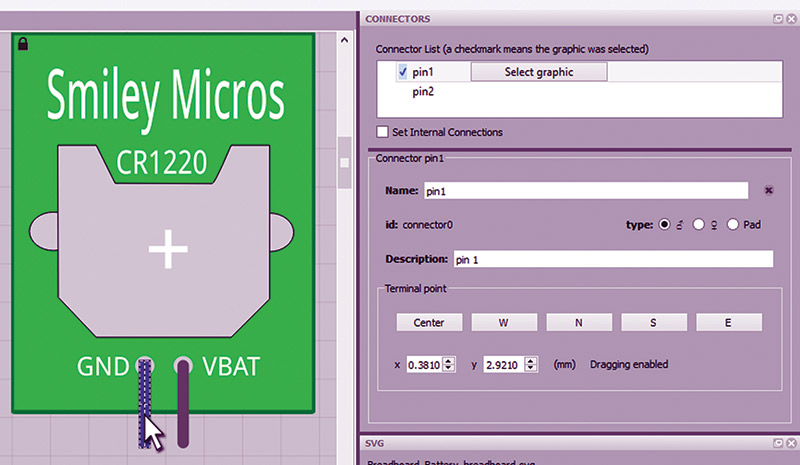
FIGURE 12. Pin 1 Select graphic.
Now, click on the pin and you'll see dotted lines forming a box with a cross in the middle. Grab the cross point and move it to near the end of the pin as shown in Figure 13. This action sets the anchor point for wires drawn between pins.
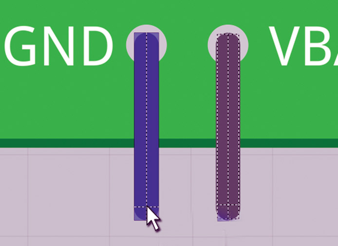
FIGURE 13. Move the anchor point center.
Repeat the process for the schematic image and then save the part. It will show up in your Mine bin as we saw before in Figure 11. Then what? Is that all? Yup! This is a lot easier to use than the old parts editor and it didn't flake out even once. Of course, I messed up (only once with the "px" thing), but I got an almost instant response back to my query on the Fritzing forum.
So, yes I'm happy with this. Not only for what it does, but also for what it bodes for the future of Fritzing. I would like to give one more big shout-out to Jonathan Cohen of Fritzing.org for all he has done. This was the Phase 1 release; I can't wait till the Phase 2 version comes out!
Moving the parts from the Breadboard to the PCB
Let's take a look at the proto shield PCB in Figure 14.
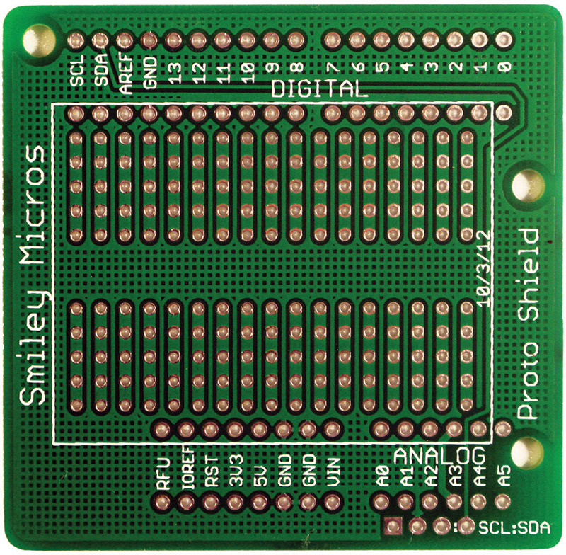
FIGURE 14. Proto shield PCB.
We can see the Arduino pins around the periphery of the PCB, but also notice that there is a matching set of pins just inside the white box border. These pins are attached to the Arduino pins which are highlighted in yellow in Figure 15.
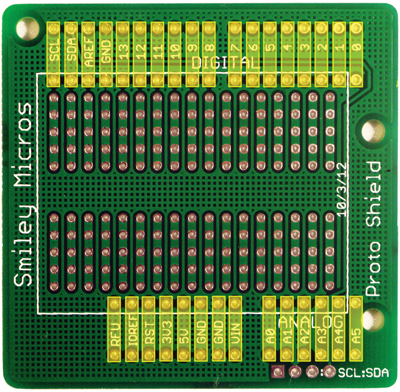
FIGURE 15. Proto shield PCB with pins highlighted.
We have two basic ways to use the proto shield: with the mini breadboard or without the mini breadboard. Notice in the center area of the PCB you see a bunch of columns of pins that are highlighted in Figure 16.
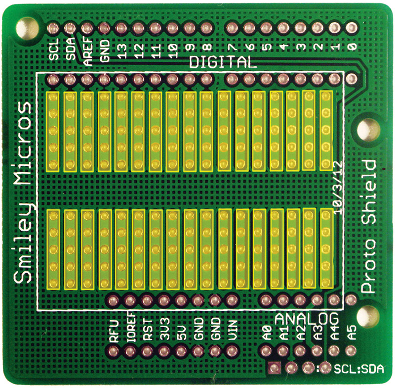
FIGURE 16. Breadboard with matching columns highlighted.
These columns exactly match the connections in the mini breadboard.
Attaching the Headers
There are two ways to use the headers on the proto shield, depending on which kit you get. In one, the headers are intended to pass the Arduino signals through the PCB and make them available via female sockets to additional shields that can stack on top of the pass-through header. In the other, regular male headers are used to attach the proto shield to an Arduino, but do not have female extensions. Therefore, they will not allow the use of additional shields above the proto shield. The pass-through male/female headers are more delicate and expensive than the cheaper and more robust male headers.
Attaching the Male/Female Pass-Through Headers
The proto shield comes with five headers. Four of the headers have long pins and are used to connect with an Arduino. The short four-pin header is used for I2C signals and will be discussed in a later article. You must be VERY careful when you are soldering the long pin headers since the pins are narrow and easily bent. If you bend these pins a couple of times they will almost certainly break, so it’s best to get them perfectly aligned before soldering them.
Place the header from the top of the proto shield PCB with the pins passing downward through the holes. Make sure you use the correct header for the particular set of holes. (Look at Figure 17 to see which header is matched to which set of holes.)
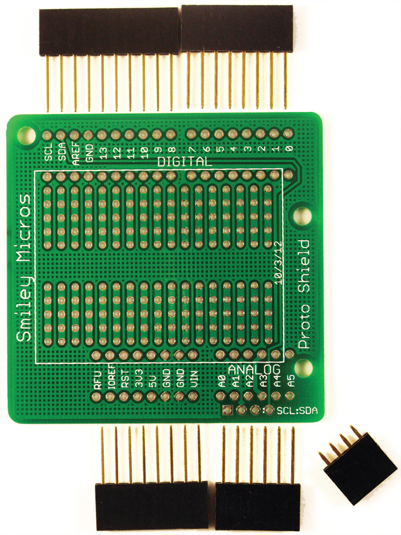
FIGURE 17. Male/female headers.
Carefully make certain that the header is exactly perpendicular to the PCB, and then lightly solder only one pin. Visually inspect it to make sure that the pins are exactly 90 degrees to the PCB. Once you get these pins soldered in you won't be able to fix any problems, so make darn sure you've got them correct before you finish the soldering.
Once the pins are all soldered, VERY CAREFULLY place them onto the matching Arduino header sockets, visually inspecting this to make sure that you have exact alignment before gently pushing them into the Arduino. This is absolutely not the place for heavy handedness. Wtih the pins pushed in place, it should now be easy to remove or reset the proto shield on your Arduino.
When you remove the proto shield, make certain that you store it in a way that won't bend the pins. Gently plugging it into a chunk of Styrofoam is probably your best bet.
Attaching the Male Only Non pass-Through Headers
The headers shown in Figure 18 are much easier to solder than the male/female headers. You simply insert these headers into an Arduino, then put the PCB on top and solder each pin.
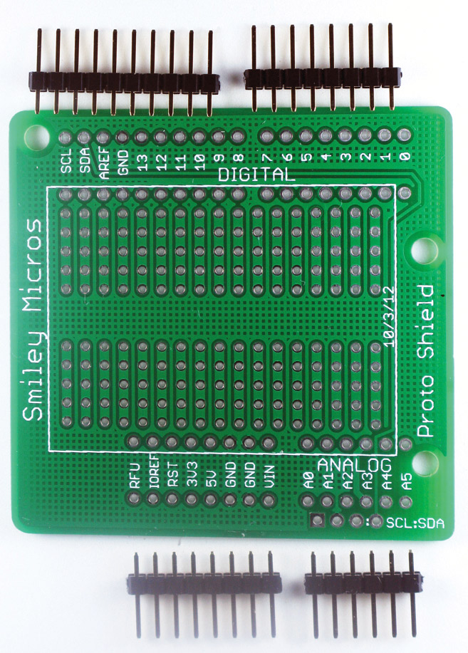
FIGURE 18. Male headers.
Header Placement for Soldering
Note in Figure 19 that we place the male/female pass-through headers through the top of the PCB so that the black plastic is all above the board.
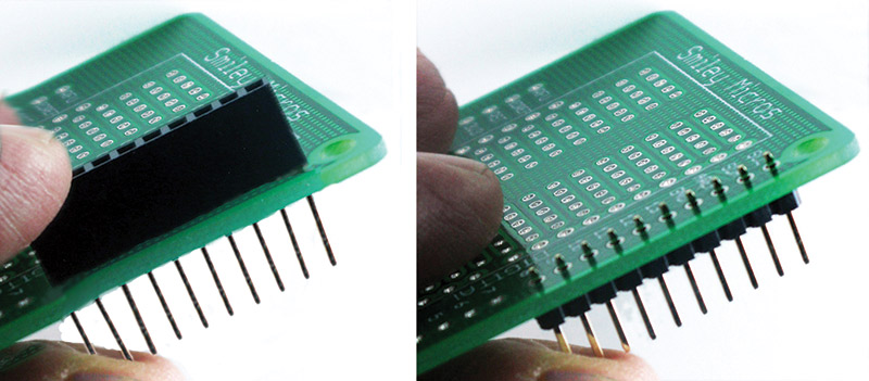
FIGURE 19. Header placement for soldering.
We do just the opposite for the male-only headers, where we place the short pins from the bottom of the PCB so that the plastic and the long pins are on the bottom.
These latter headers are easier to get straight since you can push them into the Arduino female headers and then lay the PCB on the pins so they are held in position before soldering.
Attaching the Breadboard
We can use the PCB with or without the mini breadboard. If we want to use it with the mini breadboard, we can remove the yellow base coat from the bottom of the breadboard and stick it on where we see a box marked out in white; refer to Figure 20.
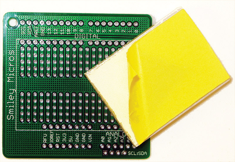
FIGURE 20. Foam tape backing.
Or, we can make it more reusable by leaving the yellow base coat on and using some double-sided sticky tape on the bottom of the breadboard (on top of the yellow base coat) as shown in Figure 21.
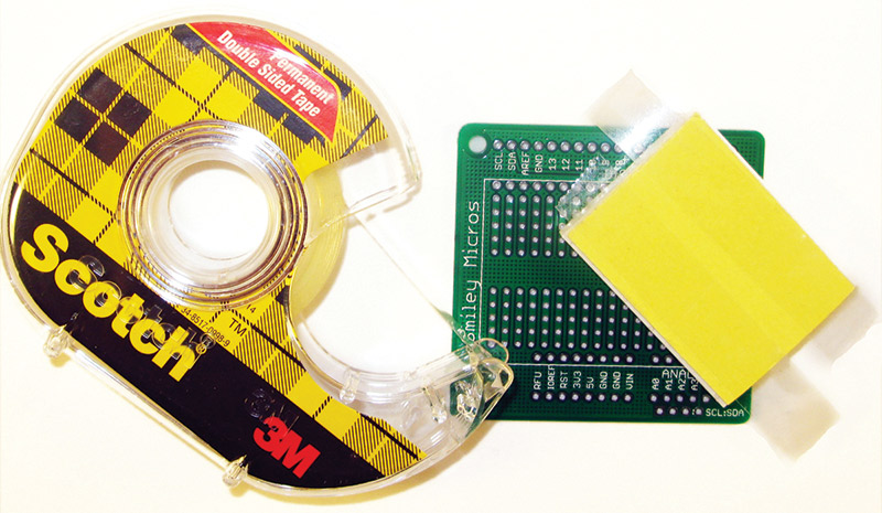
FIGURE 21. Using double-sided sticky tape on the base of the mini breadboard.
This makes it easier to attach and detach. Either way, the final position of the breadboard should resemble Figure 22.
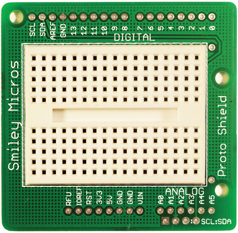
FIGURE 22. PCB with mini breadboard.
Moving a Design from the Breadboard to the PCB
In our last workshop, we built a DS1307 RTC (real time clock) based alarm clock on the breadboard. Referring back to Figure 1, it shows two proto shields: one with a breadboard containing components from last month’s project, and the other shows exactly the same components moved to and soldered on the PCB. The main difference is that on the breadboard version, the wires go to the Arduino header, while on the PCB version the wires go to the matching second set of Arduino pins just inside the white box.
I recommend that you take a picture of your working breadboard design before moving the parts to the PCB. It would be even better if you have duplicate parts for your design along with two proto shield PCBs, so that you can keep the breadboard design handy to use for debugging your PCB version.
Arduino Alarm Clock Software
Generally with the Arduino, I like to reuse other folks’ code as much as possible, but I was surprised that I didn't find a really useful alarm clock program. There were lots of similar projects, but none seemed to be doing the job I wanted. So, I decided to recycle some concepts we discussed a while back that are gone over in more detail in my book An Arduino Workshop (available from the Nuts & Volts webstore).
Using the Arduino Alarm Clock
Figure 23 shows the Windows dialog box for opening communications with the Arduino.
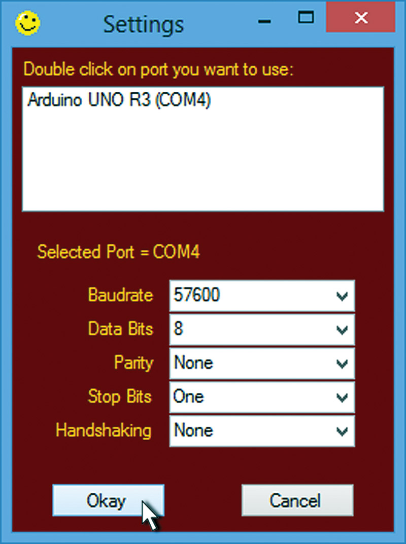
FIGURE 23. Open communications with the Arduino.
If you've been following these Workshops for a while, you may notice the resemblance of this dialog to the one we created way back in Smiley's Workshops 18, 19, and 20 on serial communications.
This dialog box and the alarm clock application shown in Figure 24 are both built on top of C# Express software created in those Workshops.
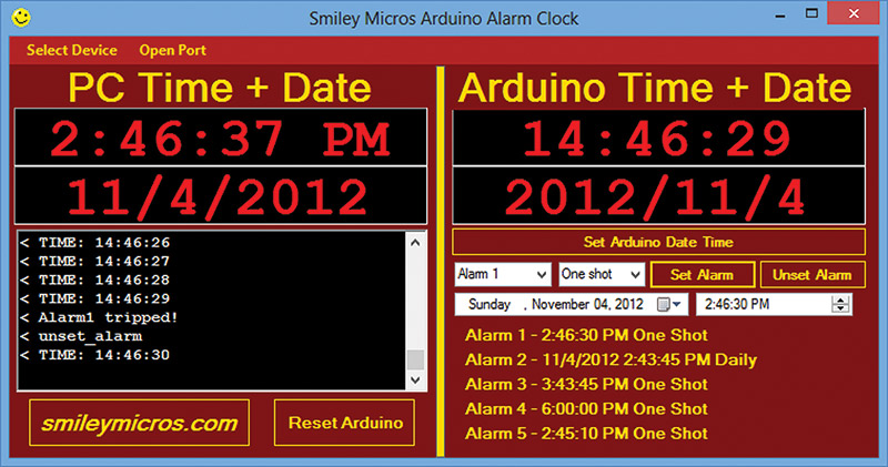
FIGURE 24. Arduino alarm clock application.
We will now briefly look at how to use this application, then next time, we'll go into more depth on how this software was written.
You can see from Figure 24 that the Arduino alarm clock application is evenly divided into halves with the left for the 'PC Time + Date' and the right for the 'Arduino Time + Date.'
This program lets us use a PC to communicate with our Arduino alarm clock, allowing us to set the date and time, and also five alarms.
These alarms can be either one shot that trip only once or daily (which will trip every day at the hour set).
Notice that the dates and times are shown in different formats on the PC and Arduino sides. The PC time is shown in a 12 hour format with either AM or PM; the Arduino time is shown in a 24 hour format.
The PC date is shown in the American standard way with the month/day/year, while the Arduino date is year/month/day.
These differences are because it is very easy to display the date and time in the common American format on a PC using C#, but is somewhat more difficult on the Arduino.
You have access to the source code, so you can rewrite it to display whichever way suits you.
Open and close the port
On the menu bar at the top of the application, you see the 'Select Device' and 'Open Port' menu items.
The Select Device will open the Setting dialog shown in Figure 24.
You can click on the 'Open Port' dialog that will toggle to 'Close Port' after you've opened it. If you are working with the Arduino IDE on that side of the code, you will need to close the port before you can upload your code to your Arduino from the Arduino IDE.
After your code has uploaded, you'll need to open the port for the application to communicate with the Arduino.
The black text window on the left side shows the messages that are sent to the Arduino marked by '>' and those received from the Arduino marked by '<.'
What does an Alarm Do?
In our design, the alarm causes the piezo element to beep using the code discussed in our last workshop. It should be noted that you could easily rewrite the Arduino code so that the alarm can instigate any action an Arduino is capable of.
You could have it turn on the light by your bed, start the coffee pot brewing, and even turn on a hotplate with a skillet full of bacon (though that might be a bit dangerous).
Last Bell
This was a very brief introduction to the alarm clock software. We will go into greater detail next time. You can find links to this software below in the downloads. NV
Downloads
Source code files for workshops 54 & 55.