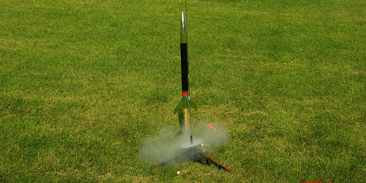
Launching model rockets is a lot of fun for kids and adults alike. Kids love the fire and smoke and trying to find the rocket once it's landed. The bigger they are and the higher they go, the better. So, how high did it go, exactly, and what did it do along the way? What happens when the rocked drifts to Earth out of sight? The flight computers described here have the ability to collect data; control other payload instruments (cameras, sensors, radios, etc.); trigger activities in flight, such as igniting a second-stage motor or deploying parachutes or glider wings; send simple telemetry data via a built-in transmitter; and act as a radio beacon to find the rocket once it's landed. With one of these as your payload, you're not just entertaining the kids — you're launching a sounding rocket and doing real science.
There are four versions of this flight computer project with varying sizes and complexity, but each has the same core functionality: a PIC16F688 microcontroller, a 64 KB EEPROM for data storage, an ADXL326 ±19g three-axis accelerometer, a multifunction ICSP/RS-232 interface, and an I/O port for analog data collection and digital control. The smallest flight computer packs these features onto a board that fits into a BT-5 sized rocket body tube (just over half an inch in diameter). The larger computers — sized to fit BT-20, BT-50, and BT-60 body tubes — add an I2C interface for external devices and a simple telemetry radio. Five of these computers fit onto one ExpressPCB MiniBoard (Figures 1 and 2). The BT-60 version uses all through-hole components, while the other versions use surface-mount parts.
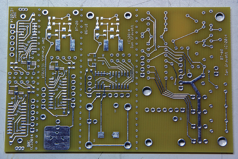
FIGURE 1. ExpressPCB MiniBoard containing two BT-5s and one each of the BT-20, BT-50, and BT-60 flight computer boards.
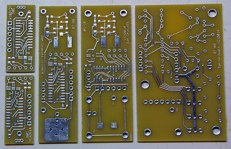
FIGURE 2. MiniBoard cut apart into individual flight computer boards.
The 14-pin PIC16F688 seems almost custom designed for an application like this. It’s physically small (especially in its SOIC surface-mount package) and can draw less than 1 mA from a three volt supply, but still has 4K of program memory, several 10-bit analog-to-digital converters (ADC), an internal clock oscillator, and internal pull-up resistors on port A and MCLR which help minimize the parts count.
The schematic in Figure 3 shows how the PIC interfaces with the rest of the components. Port A is used for ICSP, RS-232 data output, the I2C interface to the EEPROM and any external I2C devices, mode selection (flight mode or download mode), and switched power to the accelerometer and telemetry transmitter. Port C handles analog data collection from the accelerometer and external sensors, as well as digital I/O. Figure 3 also includes a simple external interface circuit (J4, J5, U4, and associated components) and external five volt power source for use when downloading collected data to a PC via RS-232, if your PC’s serial port (or USB to RS-232 converter) won’t work reliably with the three volt signal output from the computer when using its onboard battery.
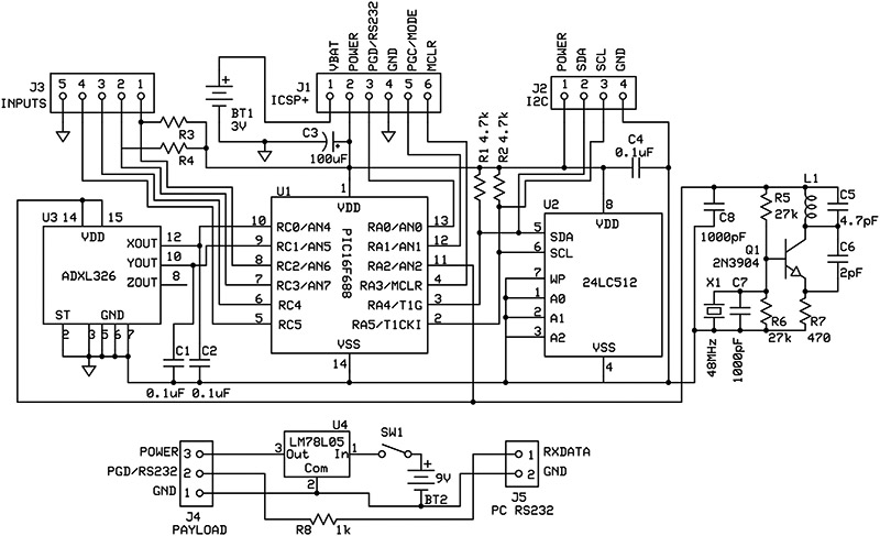
FIGURE 3. Schematic of the BT-20 flight computer. See text for differences between versions.
The telemetry transmitter is based on a design by Harry Lythall SM0VPO. Inductor L1 is 6.5 turns of bare solid 22 gauge wire wound around a 3/16” form with an overall length of about 1/2”. You can stretch or compress the inductor a bit to tune the transmitter to the design frequency of about 144 MHz, so that crystal X1 can lock in that frequency in third overtone mode; 144 MHz is at the bottom end of the amateur radio two-meter band, so you can use a two-meter portable transceiver to listen to the telemetry. Be sure to follow Federal Communications Commission (FCC) rules for licensing and station identification.
Alternatively, check out http://transmitters.tripod.com/begin.htm for component values that will yield a transmit frequency in the FM broadcast band and some possible variations on the design.
If desired, solder an antenna wire to the inductor one turn from the end connected to the positive supply voltage, being careful to route the antenna away from metal or other objects that may destabilize the transmitter. I’ve gotten a range of several hundred feet outdoors with a good quality receiver using no antenna wire at all.
The code uses pin RC4 to generate modulation signals for the telemetry radio, but as shown in Figure 3 there is no direct modulation connection to the transmitter. Close proximity of the PIC I/O line to the transmitter provides a modest level of modulation; if desired, you can connect RC4 via a simple resistor-capacitor interface to the base of Q1 or to an external transmitter for more precise modulation control.
Multifunction interface J1 serves several different purposes depending on whether you’re programming the PIC, collecting data during flight, or downloading data to your PC. During flight, pins 1 and 2 are jumpered to provide power to the computer, and pins 4 and 5 are jumpered to set the computer to flight mode.
After a flight, the jumper is removed from pins 4 and 5 to set the computer to download mode, and pins 3 and 4 provide the RS-232 data (9600 baud, 8N1) to your PC via the external power/interface circuit described earlier. Pins 2 through 6 of J1 provide ICSP control of the PIC, but note that these pins are not in the standard ICSP order (a compromise to accommodate the other functions J1 supports), so you will have to make a simple adapter cable to your favorite ICSP programmer. The physical arrangement of the pin functions in J1 ensures that the computer can only be configured for one mode at a time.
Figure 3 shows the schematic specific to the BT-20 flight computer. The BT-5 flight computer differs from Figure 3 in that it does not include I2C interface J2, filter capacitor C3, or the telemetry transmitter (transistor Q1 and associated components). The BT-50 flight computer differs from Figure 3 only in that the accelerometer’s X and Y connections to the PIC are swapped (see later discussion for why). The BT-60 flight computer has several differences from Figure 3:
- An AdaFruit ADXL326 breakout board (http://learn.adafruit.com/adafruit-analog-accelerometer-breakouts) holds the accelerometer and support components. Its onboard 3.3V regulator is unused, however.
- The J3 analog and digital I/O port is in the form of four three-pin headers with power, ground, and signal to support servomotors. Each signal line provides for a pull-up or pull-down resistor for sensors if you want to use some or all of them for that purpose instead.
- The Z axis accelerometer output is connected to the PIC, but this pin is shared with one of the three-pin I/O headers, so you can’t use both functions at the same time.
- The printed circuit board (PCB) includes a place for a three-terminal 3V regulator, so you can use a 6V main power source to power the servos and/or the telemetry transmitter. If you want to run the whole computer at 3V, just jumper the input and output pads for the regulator.
- The PCB includes places for a 2N3904 transistor and base resistor to power the telemetry transmitter from 6V under control of pin RA2. If you want to run the whole computer at 3V, just jumper from the resistor pad on RA2 to the emitter pad of the transistor.
The code for the PIC (available in the downloads) performs four main functions: configuring the PIC’s internal peripherals and I/O pins for our purposes; collecting four channels of analog data (two from the accelerometer and two from other sensors) and saving them to the EEPROM; evaluating the accelerometer data as it is collected to detect motor burnout, parachute ejection and landing and taking actions based on these events; and downloading the data via RS-232 after the flight. The PICBASIC PRO code listing includes lots of comments and notes explaining these functions as well as other details not discussed here, so be sure to take a look.
In flight mode, the computer will collect four channels of analog data every 0.1 seconds and save them during the rocket’s ascent. The rocket’s X axis acceleration data is also loaded into an eight-word array variable FIFO style, and the code looks for patterns in the data that indicate motor burnout (switch from upward acceleration to deceleration), parachute ejection (a period of deceleration followed by a sudden shock), and landing (a series of identical data points, assuming your rocket isn’t swinging from a tree branch).
The threshold values in the code used to identify these patterns are somewhat generic and may need to be modified depending on the specific acceleration profile of your rocket. The code writes “markers” into the saved data when these events are detected to make it easier to identify them when processing the data. When parachute ejection occurs, the data collection rate changes to once every second, and a simple beep is sent by the telemetry radio. After landing, data collection stops, the PIC’s ADC is turned off to save power, and the telemetry radio begins sending a series of beeps for radio location of your rocket.
Tight size constraints on the BT-5/BT-20 and BT-50 boards and the layout of the AdaFruit daughterboard on the BT-60 board prevented me from placing the accelerometer in the same orientation on each version of the computer. For all versions, I’ve defined the rocket’s X axis to be vertical — whether or not this corresponds to the X axis of the accelerometer — and assumed that the computer will be installed in the rocket with its battery end down (or its accelerometer daughterboard end up for the BT-60 version).
The accelerometer chip is turned 90 degrees on the BT-50 version relative to the other versions, so I swapped the X and Y inputs to the PIC so the rocket’s X axis data is routed to the same pin (RC1) in each version. For all versions, upward acceleration under thrust will result in vertical acceleration data values less than 512 (the accelerometer outputs an analog signal of half its supply voltage when under no acceleration,which the PIC’s ADC converts to a number in the middle of its 10-bit range), which will then switch to data values greater than 512 after motor burnout as the rocket begins to decelerate. The data-parsing subroutines in the code assume these orientation and acceleration conventions in order to properly detect motor burnout and parachute ejection, though you can omit or modify them if you need to orient your computer differently in your rocket.
Construction
Construction of the BT-60 version of the computer with through-hole parts is very straightforward; the only challenge will be choosing from the various options for the power and I/O configuration described above. Figures 4 and 5 show the top and bottom of the completed BT-60 computer.
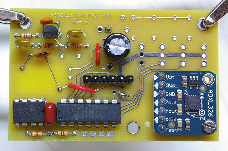
FIGURE 4. Top of completed BT-60 flight computer showing AdaFruit accelerometer daughterboard.
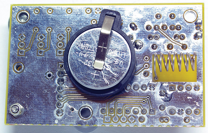
FIGURE 5. Bottom of completed BT-60 flight computer showing battery holder and inductor L1.
Construction of the three surface-mount versions is more challenging, though I deliberately picked relatively “large” versions of the parts to ease the process as much as possible. There are plenty of resources on the Internet to teach you how to hand-solder these parts including the accelerometer chip, which is only available in a tiny LFCSP package. (Based on my experience, LFCSP stands for “a Little Frustrating, but you Can hand-Solder this Package.”)
However, I deliberately omitted a pad for the Z axis output of the accelerometer as I was not confident of my ability to solder it without bridging to the adjacent ground traces. Since the Y and Z axes are pretty much interchangeable in a rocket that may be spinning a bit during its ascent, this is not a problem.
Before you solder the LFCSP to its place on the board, you will need to remove a tiny bit of the inner parts of the traces so they don’t short out through the central metal pad on the bottom of the LFCSP. I had to build the pad array for this chip from scratch as my version of ExpressPCB didn’t have a pattern for it, and I wasn’t able to position these pads any more precisely without compromising their alignment with the pads on the LFCSP. Figure 6 shows the pads trimmed prior to soldering. I had good luck using a sharp hobby knife. Figure 7 is a close-up of the LFCSP hand-soldered in place.
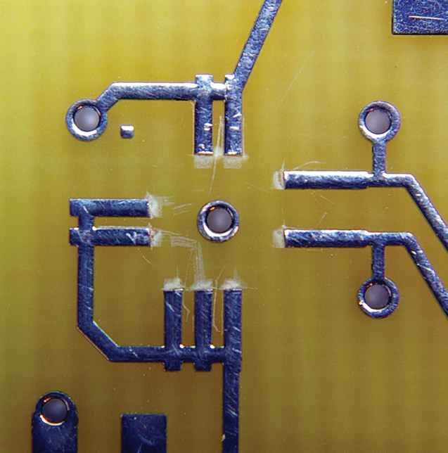
FIGURE 6. Close-up of pad array for accelerometer LFCSP, showing inner pad ends trimmed away.
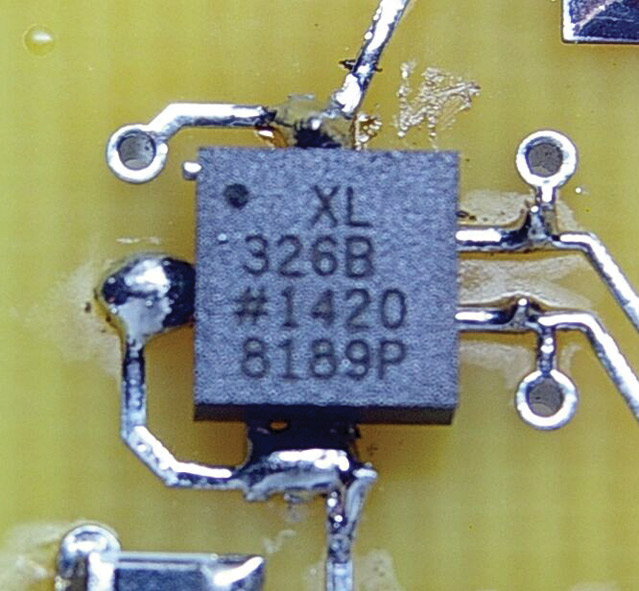
FIGURE 7. Close-up of accelerometer LFCSP, hand-soldered to the board.
The battery installation methods for the three surface-mount computers are different. The BT-50 version uses a CR-2016, -2025, or -2032 lithium coin cell held in place by a small metal plate and four screws (Figures 8 and 9) since the coin cell holder used on the BT-60 simply won’t fit inside a BT-50 tube when mounted to the PCB.
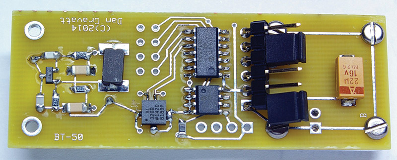
FIGURE 8. Top of completed BT-50 flight computer.
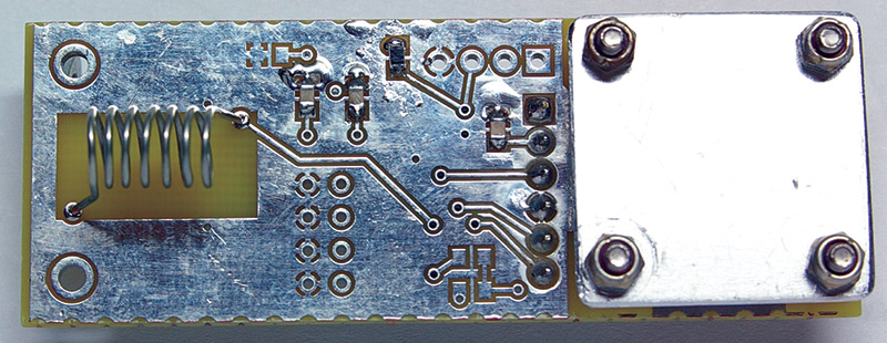
FIGURE 9. Bottom of completed BT-50 flight computer, showing metal plate and screws securing the coin cell battery.
The BT-20 version is designed to use two LR-44 button batteries — one above and one below the PCB — connected and held in place via a stiff spring metal clip that wraps around the end of the PCB. Insulate the center part of the clip so it doesn’t short out the batteries, and then use a large diameter piece of heat shrink to hold the batteries and clip securely in place.
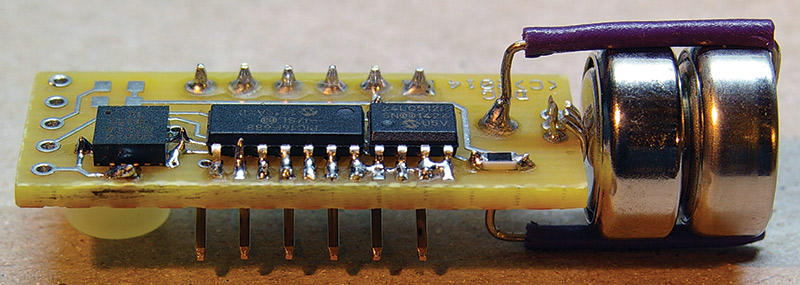
The BT-5 version is designed to use either two LR-44 batteries or one CR-1/3N lithium cell on the end of the board — connected and held in place by a contact soldered to the end of the board, and a spring wire loop from the board around the length of the battery or batteries (Figure 10). Insulate the sides of the spring wire loop if using two LR-44s so it doesn’t short out the batteries, and then use a wrap of tape to hold everything securely in place.
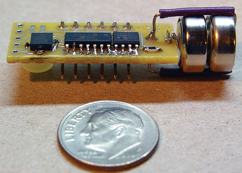
FIGURE 10. Completed BT-5 flight computer, showing details of battery holder construction.
Note that these unorthodox battery installations are only necessary if you intend to use any of the computers in the body tube diameter they are designed for. If you want to use, for example, the BT-5 version in a BT-50 diameter rocket, you can connect external power to the computer in any way that’s convenient. The BT-20, -50 and -60 computer boards include mounting holes so they can be secured to a larger payload assembly in any diameter rocket. If you do this, you must ensure that the computer is oriented properly in the rocket so the accelerometer axes are correctly aligned, or adjust the code so that the computer knows which data stream corresponds to the rocket’s X axis.
Customize It
I designed in a lot of flexibility and modularity so anyone could create a version that meets their specific needs. Both the accelerometer and the telemetry radio are optional and can be omitted. Pretty much any type of I2C-based device can be added to the I2C port, and pretty much any type of resistive or voltage-generating sensor (temperature, pressure, humidity, light, sound, etc.) can be added to the analog inputs. Pads for voltage-divider resistors (R3 and R4) for these analog sensors are available in each version of the computer. Unnecessary analog inputs can be converted to digital I/O and vice versa.
There is plenty of code space left in the PIC for more sophisticated I2C communication, data analysis, telemetry data transmission, servo control, and digital I/O control subroutines. You can also replace the 16F688 with a 16F1825, which is pin-compatible with the ‘688 and adds peripherals including hardware PWM modules and a sophisticated data signal modulator, but you’ll have to revise the code to use that chip.
However you decide to build it, this computer will satisfy your inner scientist at the same time you’re putting on a good fire and smoke show for your spectators. NV
PARTS LIST
| PART # |
ITEM |
| Surface-mount computers parts list (Digi-Key part numbers) |
| PIC16F688-I/SL-ND |
U1, Microcontroller, 14-SOIC |
| PIC16F1825-I/SL-ND |
U1, Microcontroller, 14-SOIC (optional upgrade, see text) |
| 24LC512-I/SN-ND |
U2, EEPROM, 8-SOIC |
| ADXL326BCPZ-ND |
U3, Accelerometer, 16-LFCSP |
| 399-1170-1-ND |
C1, C2, C4, 0.1 mF 50V, 0805 |
| 478-6216-1-ND |
C6, 2 pF 100V, 0805 |
| 712-1371-1-ND |
C5, 4.7 pF 250V, 0805 |
| 478-1530-1-ND |
C7, C8, 1,000 pF 50V, 1206 |
| 399-3769-1-ND |
C3, 100 mF 10V tantalum, size D |
| 311-4.70KCRCT-ND |
R1, R2, 4.7K, 0805 |
| 311-470ARCT-ND |
R7, 470 ohm, 0805 |
| 311-27KARCT-ND |
R5, R6, 27K, 0805 |
| MMBT3904FSCT-ND |
Q1, 2N3904, SOT-23 |
| 535-9853-1-ND |
X1, 48 MHz crystal, 6 mm SMD |
| S1111EC-40-ND |
J1, 40-position 0.1" 90 degree header |
| BT-60 computer parts list (Digi-Key part numbers except as noted) |
| PIC16F688-I/P-ND |
U1, Microcontroller, 14-DIP |
| PIC16F1825-I/P-ND |
U1, Microcontroller, 14-DIP (optional upgrade, see text) |
| 24LC512-I/P-ND |
U2, EEPROM, 8-DIP |
| ADXL326 |
U3, AdaFruit accelerometer breakout board |
| 296-29830-ND |
Three volt LDO voltage regulator, TO-92 (see text) |
| XC943-ND |
X1, 48 MHz crystal, HC-49 |
| 4.7KEBK-ND |
R1, R2, 4.7K, 1/6 watt |
| 27KEBK-ND |
R5, R6, 27K, 1/6 watt |
| 470KEBK-ND |
R7, 470 ohm, 1/6 watt |
| 490-7366-1-ND |
C6, 2 pF 50V, ceramic |
| 445-8586-ND |
C5, 4.7 pF 50V, ceramic |
| 445-5246-ND |
C7, C8, 1,000 pF 50V, ceramic |
| 493-1107-ND |
C3, 100 mF 50V, electrolytic |
| 445-5258-ND |
C1, C2, C4, 0.1 mF 50V, ceramic |
| 2N3904FS-ND |
Q1, 2N3904, TO-92 |
| S1011EC-40-ND |
J1, 40-position 0.1" straight header |
| BC2032-E2-ND |
BT-1, CR-2032 battery holder, PC mount |
Corrections
A change was made to the code that should prevent the computer from deciding that it has "landed" as it sits on the launch pad before launch. Found out the hard way that this can happen if your launch pad is very stable and the rocket sits too quietly.
In the line of code that begins "IF (datacomp[0] = datacomp[1]) and (datacomp[1] = datacomp[2])..."
add the condition "and (ejectflag=1)" before THEN
Downloads
What’s in the zip?
Source Code
Express PCB schematic and PCB files