The two basic ways to transfer digital data from one place to another are parallel and serial. Parallel data transfers send all bits of a word at once with one bit per wire. To send a byte, for example, you need eight wires or conductors in a cable (plus ground). To transfer that byte serially, all you need is one wire (plus ground). Each bit is sent for a fixed time period, one at a time in sequence. Today, both methods are still used, but in most applications a serial interface is implemented.
Parallel transfers are generally faster, but are more expensive as they require more hardware and wires. Furthermore, as parallel wires get longer, the inter-wire capacitance and the inductance of the wires greatly impacts data rates, so shorter connections are necessary to get any speed. Parallel connections run out of steam at about 100 Mb/s, and that can be achieved only over a foot or so. Serial is less expensive, simpler, and can achieve high speeds over longer distances.
There are literally dozens of different serial interfaces in use. Virtually all electronic devices today have a serial interface port of some kind. It is useful to know some of the basic details of these interfaces that you may use every day. This first article covers the slower interfaces such as CAN, I2C, RS-232, RS-485, and SPI. The second part of the article will cover USB, HDMI, PCIe, and a few others.
RS-232
The oldest serial interface is designated as RS-232 and was initially used in teletypewriters, computer video terminals, and modems. Later, it became a popular peripheral interface for PCs. Remember the PC serial port interface for printers and other devices? While PCs no longer have RS-232 serial ports, this interface is still around and found mostly in industrial equipment like programmable logic controllers (PLCs), robots, industrial computers, and some wireless gear. It is cheap and reliable.
The RS-232 interface transmits data seven or eight bits in sequence from LSB to MSB (see Figure 1).
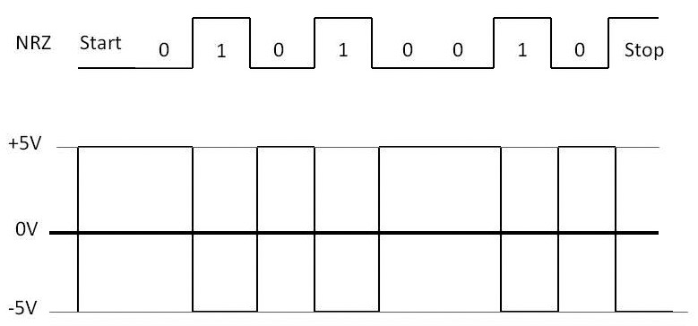
FIGURE 1. Asynchronous data transmission with the RS-232 interface converts the normal NRZ (upper signal) into a bipolar RS-232 format shown in the lower waveform. Start and stop bits are added. The ± 5V levels are typical.
The standard NRZ (non-return to zero) binary data gets sent as a bipolar logic signal, where a binary 1 is some voltage between -3 and -25 volts and a binary 0 is a voltage level between +3 and +25 volts. Both +5 and +12 volt levels are common. Note that there is a start bit (logic 0) signaling the beginning of a word transfer and a stop bit (logic 1) that determines the end of the word. A parity bit is sometimes added between the end of the word and the stop bit for error detection.
This word format is implemented by a circuit called a universal asynchronous receiver transmitter, or UART. It may be a single IC or integrated on another chip such as a microcontroller. It handles all of the parallel-to-serial and serial-to-parallel data conversions, as well as adding and removing the start, stop, and parity bits. It also sets the speed.
As for the speed or data rate (R), it is simply the reciprocal of the time for one bit (t):
R = 1/t
As an example, for a bit time of 104.167 microseconds, the data rate is 9600 bits per second (bps or b/s).
Knowing the data rate, you can find the bit time:
t = 1/R
If the data rate is 1 Mbps, the bit time is one microsecond.
The RS-232 interface defines multiple data rates depending on the application. Some common standard rates are 9600 bps, 19.2 kbps, and 115.2 kbps. The upper limit is really determined by the cable length. Long cables have lots of capacitance, so rounding off the leading edges of the binary pulses minimizes the data speed. Cable lengths are generally less than 50 feet.
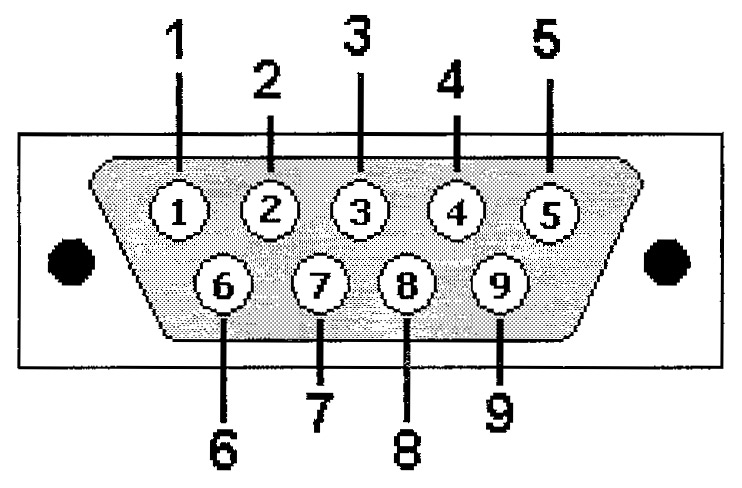
The RS-232 standard also specifies a connector. The early versions used a 25-pin connector, but today a nine-pin connector is the most common (refer to Figure 2). Early applications used several of the control lines to implement communication protocols, but today mostly only the transmit (TD) and receive (RD) lines are used.
| Pin Names |
| 1 |
DCD |
Data carrier detect |
| 2 |
RD |
Receive data |
| 3 |
TD |
Transmit data |
| 4 |
DTR |
Data terminal ready |
| 5 |
GND |
Signal ground |
| 6 |
DSR |
Data set ready |
| 7 |
RTS |
Request to send |
| 8 |
CTS |
Clear to send |
| 9 |
RI |
Ring indicator |
FIGURE 2. The most commonly used connector for the RS-232 interface uses nine pins and is called a DB9 or DE9. Usually, only the RD and TD data lines are utilized, but other control lines are adopted for some protocols.
I2C
I2C, or the Inter-Interconnect bus is an interface developed by Philips (now NXP Semiconductor) to connect one complex IC to another on a printed circuit board (PCB). The transmission medium is just the copper pattern on the PCB. It can also use a short cable to connect two PCBs or other devices.
The physical arrangement consists of a master control IC like a microcontroller and one or more slave devices that receive the data or send some of its own back to the master (Figure 3).
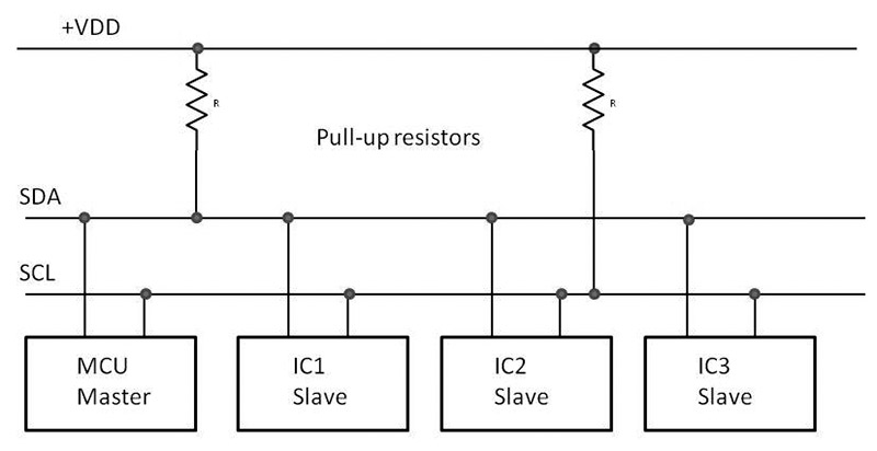
FIGURE 3. The popular I2C interface uses a master and one or more slave devices. External pull-up resistors are used on the MOSFET drivers inside each chip. The typical application is intercommunications between ICs.
Note that there is a data line (SDA), a clock line (SCL), and a ground wire forming a bus. Up to about 30 slave devices can be accommodated if the bus connections are not too long. Bus length is usually less than one foot on a PCB or no more than several feet for a short cable. Bus length limits data rate.
Data is sent by way of a frame or packet that contains a start bit, a seven- or 10-bit slave address, a read/write bit followed by the data bytes to be sent with each followed by an acknowledge bit (Ack), and finally a stop bit. The basic data rate is 100 kbps, but higher speeds such as 400 kbps, 1 Mbps, and 3.4 Mbps can be used if the bus capacitance is not too great.
There are several variations of the I2C bus. A common one is the system management bus (SMB) developed by Intel. It is used to communicate between chips on PC motherboards. A variation of the SMB is the power management bus (PMB) that is used for controlling and monitoring power supplies and ICs like regulators or DC-DC converters. Another version is the two-wire interface (TWI) used by Atmel.
SPI
The serial peripheral interface (SPI) is similar to the I2C bus since its primary application is interconnecting chips on a PCB or linking two PCBs over a short cable. The primary difference is that SPI is significantly faster. SPI is integrated into many fast embedded controllers, as well as memory devices like Flash, I/O chips, DACs, ADCs, FPGAs, and other fast peripherals.
Data rates are usually 1 Mbps or more, up to about 50 Mbps. Range is no more than a few feet, and usually only inches on a PCB.
Figure 4 shows the usual connection. Master devices — typically, the microcontroller — select a slave with a slave select (SS) line and initiate a read or write operation. Note the two data lines: master out slave in (MOSI) and master in slave out (MISO). A clock line times the synchronous transfer of data by bytes or longer words. There are no start or stop bits. Multiple slave units can be accommodated. A slave select line is needed for each.
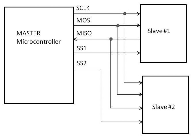
FIGURE 4. Another popular chip-to-chip interface is SPI. It is faster than I2C and uses a few more lines to link a master controller to one or more slaves. Each slave is enabled with a slave select (SS) line.
CAN
The controller area network (CAN) bus is especially designed for automotive applications. It is used to transfer data between multiple electronic control units (ECUs) in a vehicle such as sensors, actuators, and other devices to control the transmission, engine, suspension, brakes, or other systems. It is also used in some industrial control applications.
CAN is especially reliable as it uses shielded twisted pair cable that can be many meters long. The differential pair cable, along with the shield, effectively reduce the noise level in harsh environments, thereby producing fewer bit errors. Data rates depend on usage, but can range from 10 kbps up to 1 Mbps.
The wire bus is differential with two lines (CANL and CANH) for high and low signals. Up to 127 nodes may be paralleled along the bus. The bus can run up to 1,000 meters but that limits the data rate to no more than 40 kbps at that range. Each node on the bus is a transceiver that may send or receive data. Nodes compete for bus usage with a contention process that gives the bus to the node with the highest priority. Data is then sent byte by byte with asynchronous start and stop bits.
There are several variations of CAN, including CAN 2.0A and CAN 2.0B. Others are CANopen used in industrial applications, DeviceNet used in factory automation, and J1939 — a Society of Automotive Engineers (SAE) variant for trucks and buses.
CAN may be integrated into microcontrollers or other ICs. However, separate CAN transceivers and controllers are also available.
RS-485
Another popular serial standard is RS-485. Like CAN, it uses differential shielded or unshielded twisted pair cable to form a bus. The differential configuration helps cancel noise over long distances. Cable length can be up to 4,000 feet, but it does limit the data rate to about 100 kbps. Data rates to 10 Mbps can be achieved at up to 40 feet. Depending on the type of line driver and bus length, speeds up to about 35 Mbps can be achieved.
The bus can have up to 32 nodes on it. Each node is a transceiver that may send or receive. Separate IC transceiver chips are commonly used.
As for applications, it is variable. Mostly, RS-485 is found in industrial applications but it also shows up in building automation, video surveillance, and point of sale terminals.
There is no fixed transmission protocol, so any solution can be used. Transmission is usually asynchronous byte by byte using start and stop bits.
Other Interfaces
As I said earlier, there are dozens of other serial I/O interfaces. Just a few are 1-Wire, BitBus, FlexRay, IOLink, I2S, LIN, Microwire, MIDI, OBD, and X10. Most were developed for specific applications and many are similar in operation. Some of the faster interfaces are more widely used. I will cover the most popular of these like USB, Ethernet, and PCIe in Part 2. NV