A barn door tracker — also known as a Haig or Scotch mount — is a device that slowly rotates a camera, allowing it to track the stars so it can take long exposure photographs of the night sky. High end astronomical telescopes usually have what's called a clock drive, which slowly rotates the telescope allowing for those long exposure photographs. The barn door tracker can take long exposure photographs with your camera without a telescope.
While it looks like the stars move across the night sky, it is actually the Earth's rotation that the barn door tracker must match. A barn door tracker gets its name from the two plates hinged together along one edge that when swinging, act like a barn door. One plate is attached to a tripod or other mount, while a motor driven threaded rod raises the other plate at approximately the same angular rate as the Earth turns. A small finder telescope is attached to help with aiming so that the axis of the hinge pin is pointed to Polaris, the pole star. This places the base plate at an angle from the horizon equal to the local latitude, with the hinge pin parallel to the Earth's axis.
Figure 1 shows the basic geometry of the tracker. The threaded rod is attached to swivel mounts. (See the sidebar and construction section for more details.) Two pieces of cabinet grade 3/4 inch plywood are joined together by a hinge made from telescoping brass tubing. A 1/4-28 threaded rod joins the plywood plates. A stepper motor attached to the bottom of the threaded rod serves to turn it, which pushes up the top plate and rotates it about the hinge axis. A camera mounted on the top plate then rotates in synchronization with the Earth’s rotation.
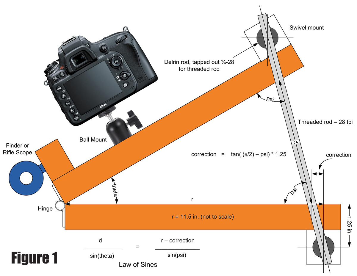
Figure 1.
There is another detail we need to mention here. One would think the barn door should rotate at a speed of one rotation in 24 hours. Instead, it needs to rotate at the sidereal rate.
A sidereal day is 23 hours, 56 minutes, and 4.0916 seconds. As the Earth takes one solar day to rotate, it also is revolving around the Sun. Therefore, a star appearing directly overhead will take slightly less than one solar day to appear directly overhead again.
Construction
Referring to Figure 2, at the top the threaded rod goes through a pivoting nut made of 5/8 inch Delrin rod, although other plastics may work as well. A hole is drilled through the Delrin rod at a right angle to the rod’s axis, and is then tapped out with 1/4-28 threads. The Delrin rod is mounted in L-shaped UHMW (ultra high molecular weight) polyethylene blocks that are screwed down to the top plate. This material is somewhat similar to Teflon but has better abrasion resistance.

Figure 2.
At the underside of the bottom plate, the stepper motor is mounted to a longer piece of pivoting Delrin rod flattened on one side, and is mounted in L-shaped UHMW polyethylene blocks. A hole is cut through the Delrin rod for the stepper motor shaft. An aluminum coupling with two set screws attaches the threaded rod to the stepper motor shaft. As the top plate moves up, the pivoting nut must move to the left. This is accommodated by allowing both ends of the threaded rod to pivot, maintaining the geometry of the isosceles triangle.
There are many variations on how to increase the accuracy of a barn door tracker. This design computes the angle needed in real time several times a second to accurately move the camera at the sidereal rate. The rate at which the screw turns varies with the distance d, giving rise to difficulties in other designs. There are different approaches as to how to accommodate this varying rate.
The use of a piano hinge has been criticized and can lead to inaccuracies that show up in exposures as star trails. I used two pieces of brass telescoping tubing for the hinge with the outer tube soldered to brass strips, making a hinge that tracks more accurately. With the hinge pin being a small hollow tube, this is also a very useful feature in sighting the north celestial pole. Figure 3 shows details on how the swivel mounts and hinge were constructed, and Figure 4 shows the mounted improved hinge.
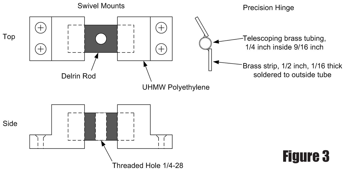
Figure 3.
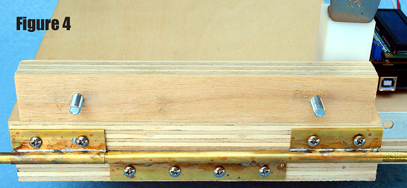
Figure 4.
By not cutting down the 12 inch hinge pin tube, the longer length works better for sighting Polaris. The bolts above the hinge mount a finder telescope.
Figures 5 and 6 are views of the barn door tracker on a telescope tripod.
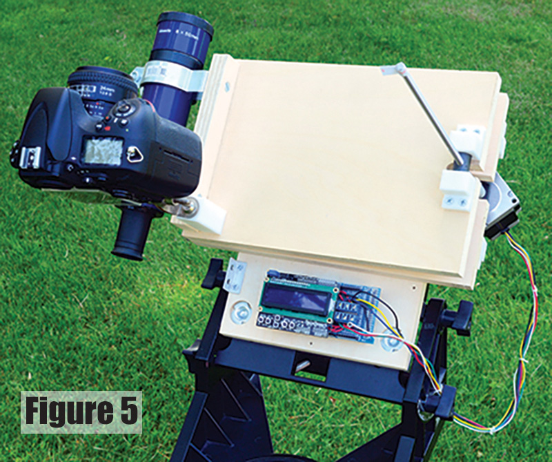
Figure 5.
Actually, any sturdy mount works as long as the hinge axis can be pointed at the north celestial pole, which is very close to Polaris. I used a finder telescope from an astronomical telescope, but something like an inexpensive air rifle scope could be used as well.
For the camera mount, I used a ball mount that screws into the 1/4-28 mounting hole (found on most cameras) which attaches to the top plate. This allows the camera to be pointed to the desired position in the sky.
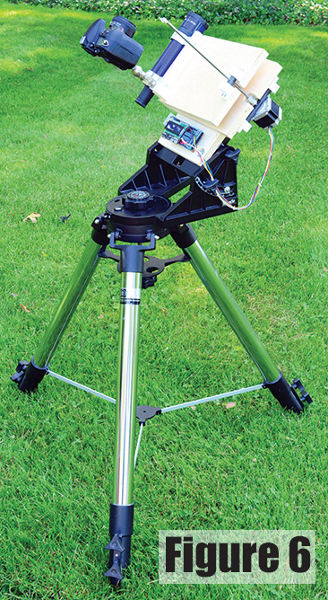
Figure 6.
It is important that the threaded rod is straight and turns easily through the Delrin nut, and that both pieces of Delrin rotate easily in their UHMW polyethylene mounts. Any binding may cause the stepper motor to bind.
While it is possible to drive the stepper motor with an integrated circuit for that purpose, I choose to drive it directly with MOSFET transistors controlled from an Arduino board. The program will deal with the necessary signals to switch the MOSFET transistors on and off. The Arduino board and its associated shield are mounted on the base of the barn door tracker. The Arduino board and additional circuitry can be powered with a 7.2 volt NiCd battery for portability or a standard plug-in power supply.
The Circuit
The schematic of the stepper motor driver is shown in Figure 7.
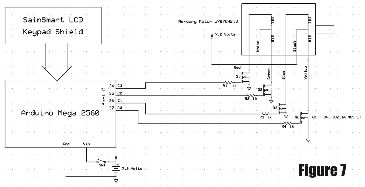
Figure 7.
The circuit consists of an Arduino board with four of its outputs driving MOSFETs that control the current through the four coils in the unipolar stepper motor. The MOSFETs are mounted on a Arduino Mega 2560 prototype board which is shown in Figure 8.
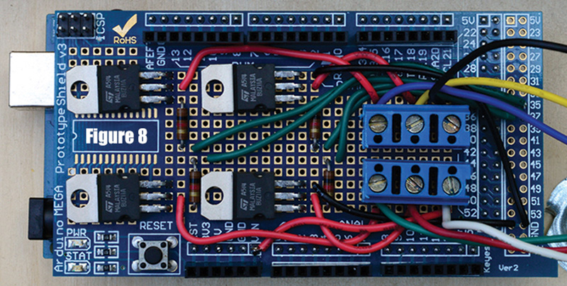
The Mega 2560 board was chosen because the prototype board was larger and allowed for the easy positioning of the MOSFETs and the terminal posts. This allows the stepper motor wires to be easily connected. The prototype shield used has a duplicate set of headers allowing for the insertion of a SainSmart LCD shield which is a convenient addition. We then have two piggyback shields plugged into the Arduino board.
The LCD shield allows for visual feedback on the progress of the stepper motor and its attached threaded rod. It also contains six small contact switches which are used to control the operation of the barn door tracker. The up and down switches set the direction of travel; Up being the direction used for tracking the stars at the sidereal rate. Down is used in conjunction with two other keys labeled Select and Left. The Select switch sets the stepper motor to track the stars, while the Left switch turns on a higher speed slew rate to return the barn door tracker to its starting position. These switches are connected to the A0 analog input port and are read using the analogRead(0) command. When tracking starts, the plates must begin in the closed position — the default position needed when the software starts running.
Figure 9 shows the SainSmart LCD keypad shield plugged into the prototype board. The output shown has the elapsed sidereal time on the first line, with the second line showing the number of steps taken and the angle of the two plates given in degrees.
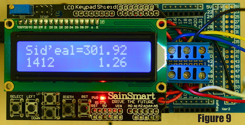
Figure 9.
A unipolar stepper motor was selected because it can operate from the same power source as the Arduino board, and the drive circuitry is quite simple. There are many surplus stepper motors available through electronics dealers that advertise here and on the Internet. The only criteria when choosing a unipolar stepper motor is that the voltage be fairly close to the voltage used to power the Arduino board, and that it have enough torque to drive the threaded rod.
I selected the Mercury Motor 57BYGH213 because it is rated at one amp and 6.2 ohms, and has a 1.8 degree step. So, a 6.2 volt power supply will provide enough current. The torque rating is 9 kilogram centimeters which works very well. Voltages slightly higher than the 6.2 volts can be used without damage to the stepper motor. I use a nine volt plug-in power supply when not using the 7.2 volt NiCd battery. The BUZ11A MOSFETs chosen have internal diodes to protect them from the back inductive kick of the motor coils.
The Program
To get the stepper motor to turn, current needs to be sent through its four coils in a specific sequence. Table 1 shows the sequence for the steps that will turn the shaft clockwise when looking at the shaft. If instead, the order of the pattern is reversed, the shaft will turn counter-clockwise. Each step of the motor will turn the shaft 1.8 degrees, so 200 steps are needed to get a full revolution
| Step |
Q4 |
Q3 |
Q2 |
Q1 |
| 1 |
Off |
On |
On |
Off |
| 2 |
On |
Off |
On |
Off |
| 3 |
On |
Off |
Off |
On |
| 4 |
Off |
On |
Off |
On |
| 1 |
Off |
On |
On |
Off |
Table 1.
Table 2 lists a sequence of eight different patterns called the half step sequence.
| Step |
Q4 |
Q3 |
Q2 |
Q1 |
| 1 |
Off |
On |
Off |
Off |
| 2 |
Off |
On |
On |
Off |
| 3 |
Off |
Off |
On |
Off |
| 4 |
On |
Off |
On |
Off |
| 5 |
On |
Off |
Off |
Off |
| 6 |
On |
Off |
Off |
On |
| 7 |
Off |
Off |
Off |
On |
| 8 |
Off |
On |
Off |
On |
| 1 |
Off |
On |
Off |
Off |
Table 2.
Sending this sequence will rotate the shaft one half of the step angle or 0.9 degrees, requiring 400 steps to turn the shaft one rotation. The following sets of data representing these patterns are stored in our Arduino program:
byte fullsteps[4] = {0x06, 0x0A, 0x09, 0x05};
byte halfsteps[8] = {0x04, 0x06, 0x02, 0x0A, 0x08, 0x09, 0x01, 0x05};
Note that we are using only the low four-bit nibble of each byte. We will output each byte to port C, and connect the four wires going to the MOSFET gates to the lower four bits of port C. These are pins 34-37 on the Arduino Mega 2560; pin 37 is the least significant bit.
The program follows the algorithm shown in the sidebar. Using the geometry above, the program calculates how high the threaded rod must be raised given the current sidereal time, and then calculates how many steps of the stepper motor are needed. The program keeps a running total of the steps taken and then adds steps to raise the threaded rod the required distance. The complete program is available at the article link.
Accuracy
There are several things that will affect the accuracy of the barn door tracker. They are:
- Most important is the accuracy in pointing the hinge pin at the north celestial pole.
- The accurate measurement for the r value — the distance from the hinge to the center of the threaded rod.
- The accurate measurement for the distance from the top of the bottom plate to the center of the bottom Delrin rod. This is used in the correction formula.
- Step size of the stepping motor.
In reviewing this list, the accuracy of pointing the hinge pin and the physical measurements in 2 and 3 are going to have the greatest effect on accuracy. After building the barn door tracker, check these measurements. If there are slight differences, those corrected values should be used in the appropriate formulas. Some sort of finder scope attached in parallel to the hinge axis is also helpful. Using a distant object in daylight or the moon, the finder scope can be adjusted to match the view through the hollow hinge pin. Viewing Polaris through the hinge pin can be difficult — especially with a bright sky in an urban environment. The step size can be changed to 400 steps per turn, but this improvement in accuracy is overshadowed by the first three items in the list. The dominant factor in accuracy is pointing the hinge pin at the north celestial pole.
The Results
Figure 10 is a portion of a four minute exposure at F/8 taken using the barn door tracker with a Nikon D810 digital camera, Nikon 50 mm F/1.4 lens, and a Lumicon high contrast filter to reduce the bright sky in my neighborhood.
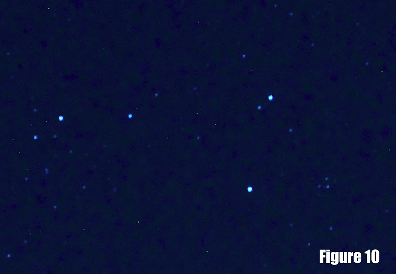
Figure 10.
These shots are some of the first ones taken with the barn door tracker as a proof of concept, and are not the best quality. The stars shown are from the bend in the neck of the constellation Draco at approx. right ascension 19 hours, declination 70 degrees.
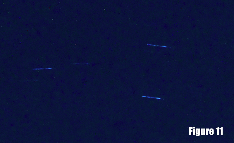
Figure 11 shows the same area with the barn door tracker turned off. Further details on taking photos with a barn door tracker can be found on Internet sites. NV
The Geometry (sidebar)
Referring back to Figure 1, look at the isosceles triangle created by the two wooden plates and threaded rod. The length of the base of the triangle created by the threaded rod is labeled d, while the length of the sides are labeled r. The angle created by the two wooden plates is labeled theta and the two equal base angles of the isosceles triangle are labeled psi. Here is the sequence of the algorithm for calculating how high to raise the top plate at a distance d for a given elapsed time in solar seconds, beginning with the two plates closed creating an angle theta of zero:
1. Set solar_time = 0, total_steps = 0, r = 11.5.
2. Read elapsed solar_time in seconds.
3. Convert solar_time to sidereal time by multiplying solar seconds by 1.0027379.
sidereal = solar_time * 1.0027379
4. Calculate angle theta in radians. A circle contains 2 * PI radians, or about 6.24 radians. Angles are calculated in radians because this is the unit necessary when using trigonometry functions in the Arduino program. Assume the barn door will run for at most three hours, or 10,800 seconds. Therefore:
theta = (sidereal time / 10800.0) * (PI / 4.0)
where (sidereal time / 10800.0) is the fraction of three hours using seconds for both values, and (PI / 4.0) is the angle in radians theta that would subtend in three solar hours.
5. Next, calculate the angle psi. The sum of a triangle's angles is
180 degrees, or PI radians. Because the two base angles are equal in an isosceles triangle:
psi = (PI - theta) / 2.0
6. Using the Law of Sines which relates the lengths of the sides of a triangle to the sines of its opposite angles:
d / sin(theta) = r / sin(psi)
d = r * sin(theta) / sin(psi)
7. The number of steps the stepper motor needs to have taken for this time is:
steps = (d * 28.0) * 200.0
given 28 threads per inch and 200 steps needed for each rotation of the threaded rod.
8. As the elapsed time progresses, keep track of the number of steps the stepper motor has completed, adding steps as necessary to maintain each newly calculated distance d:
while (total_steps < steps)
{
have stepper motor do one step
total_steps = total_steps + 1
}
9. Loop back to number 2.
The algorithm here works fine for the first few rotations of the stepper motor. However, as the threaded rod moves the top plate up, the rod itself starts to angle to the left on its swivel mounts. This changes the geometry as the distance r is reduced. The center of the swivel mount is located 1.25 inches below the top of the bottom plate. The angle of the triangle created when the threaded rod moves over is the complement of psi, or 90 degrees psi, which is
PI / 2 psi in radians. These formulas are:
comp_psi = (PI / 2.0) - psi
correction = 1.25 * tan(comp_psi)
This correction amount must be subtracted from r before r is used in number 6 above.
PARTS LIST
| ITEM |
SOURCE |
| Mercury Motor 57BYGH213 or similar |
Electronic Goldmine |
| Arduino Mega 2560 |
Adafruit, Sparkfun |
| Arduino Mega 2560 prototype board |
Sparkfun |
| SainSmart LCD keypad shield |
SainSmart |
| BUZ11A MOSFET transistors, 1K resistors, terminal posts |
All Electronics |
| Hookup wire, solder, 3/4 inch plywood, wood screws, machine screws, coupling between stepper motor and threaded rod |
Home Depot, Lowes |
| Delrin rod, 5/8 inch, UHMW polyethylene |
ePlastics |
| 1/4-28 stainless steel threaded rod, 12 inches long |
eBay |
| Telescoping brass tubing and brass strip |
Tower Hobbies |
| Finder scope and mounts, or small rifle scope for an air gun |
Amazon |
| Camera ball mount, tripod, or other base |
Amazon, B & H Photo |