Are you thinking about building a DIY project that requires using a complex electro-mechanical system, but you have limited electro-mechanical building experience? Well, you don’t need an engineering degree to succeed with your project. In this article, I’ll give you some common sense approaches to maximizing your radio control system and dealing with electrical issues. I’m hoping I can empower you to begin your project while sharing with you some of the electro-mechanical problems I solved. My submarine had issues unique to a submersible project; however, I solved many of these unknowns — like air tank design and air compressor engineering. Many of my building issues were the same as those which any electro-mechanical project might have. I would always go to the electrical supply store and ask questions.
The Air Compressor
The air compressor in Figure 1 is the key feature of this system. Using an onboard air compressor allows the submarine to surface, add compressed air to the holding tank, and submerge again. I removed this little air compressor from a 12 volt tire inflator system. This compressor was designed to plug into your automobile cigarette lighter which should be connected to your car tire to inflate a flat tire. I cut the connecting line to the tire to make it fit into the small work space within the seven inch PVC tube. The compressor was rated at 250 PSI. It compresses to about 90 PSI in my holding tank.
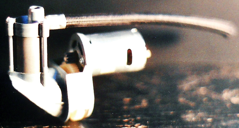
FIGURE 1.
This 12 volt air compressor was the basis for my using the same voltage system on my submarine, although there are other compressors of this nature which would work, as well. Figure 2 shows the compressor installed in the holding bracket.
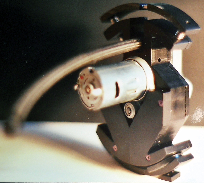
FIGURE 2.
I built up this bracket/stabilizer as a cardboard and wood prototype. Later, I made the parts out of aluminum and had them anodized to protect them from rust. Figure 3 shows the compressor in its location in the PVC tube. Figure 4 shows the copper tank which holds the compressed air, and a side view of the completed compressor system.
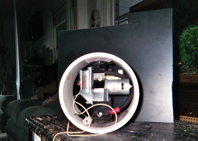
FIGURE 3.
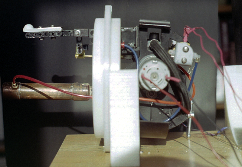
FIGURE 4.
Compressed Air-Holding Tank
The purpose of the holding tank is to keep the compressed air in a pressurized state until it is needed to blow water out of the ballast tank to surface the submarine. The holding tank is made from off-the-shelf, one inch copper plumbing tubing. The copper tube is made up of four things. There are two end-caps soldered in place and a small brass barb fitting. The fourth is the one inch copper tube to which the latter is attached to connect air-tubing passing to a Clippard valve inside the compressor chamber to release the compressed air when needed. The ballast tank and the compressor compartment are back-to-back with holes to allow the passage of a pushrod to operate the ballast tank and an air release port. The input end of the holding tank holds air due to the presence of a Schrader valve in the brass-fitting input. The input in Figure 4 is the end of the copper tank connecting to the white PVC pipe.
The Schrader valve is the valve in a bicycle or car tire. I removed a Schrader valve from a bicycle tire and burned the rubber off of it. I threaded a brass fitting to fit the Schrader valve and valve stem. The valve required silver soldering with MAPP gas to seal the brass fittings into the copper tube. Care must be taken when doing this type of silver soldering. Also, the Schrader valve must be unscrewed and removed before the soldering, as it has a rubber seal built into it. The rubber seal on the valve cannot be damaged by the heat of the soldering procedure. If the rubber seal is damaged, it won’t seal completely. (The MAPP gas procedure was covered in Part 1 of this series.)
To test the copper tank, I used a great little device with the strange name of “manometer.” The manometer is a battery-operated device that tests air pressure. I used a compact version and connected it to the tank as shown in Figure 5. The air compressor is turned on and fills the tank while the manometer indicates the pressure accumulating in the tank. When the maximum pressure is reached, the compressor is turned off; this is when I would watch the manometer. If the pressure holding tank holds its pressure, the manometer would not change its pressure reading.
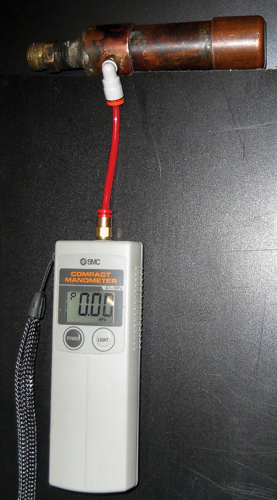
FIGURE 5.
I encountered problems with this simple little tank. One issue was having to learn to use the MAPP gas system which had some backward type functions. Also, I unknowingly damaged the seat of the Schrader valve by overheating the seat area. This was while I was silver soldering it, and thus, I had to re-make the tank. The new tank turned out to be a good thing because I made it larger. The second tank worked fine. Figure 4 actually shows the completed air-compressor system with the air-release valve to the upper left. (Yes, those are LEGO pieces.) This device became a prototype in itself, and I left it at that. That valve tip is made of the mold compound I used to cast the rudders and hatches. There is a servo connected to the air-compressor bracket which activates the LEGO arm via a bulkhead seal. This valve will open a small hole in the top of the ballast tank to allow air to escape, and permit water to enter at the bottom of the tank and submerge the sub.
Figure 6 shows the rear view of the air-compressor chamber with the two yellow Clippard valves.
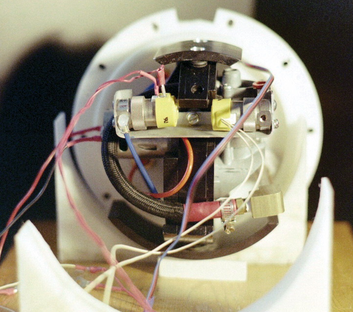
FIGURE 6.
The Clippard valve on the right allows air to enter the chamber when the air-compressor is activated. The Clippard valve on the left holds back the compressed air in the compressed air holding tank, and releases the air to blow water from the ballast tank, allowing the submarine to surface. Here, I learned a lesson regarding wire gauge. During my testing of the compressed holding tank, I found that the air compressor would stop running before the tank had reached full capacity. The problem was that the thickness (gauge) of the wire going from bulkhead to bulkhead was too thin. The compressor worked until it had too much built-up pressure for the air-compressor to handle. The air-compressor motor couldn’t draw enough amps through the thin wire to continue operating. Adding thicker wires solved the problem of the motor stalling. Figure 7 shows the completed PVC tanks, while Figure 8 shows the servo/micro switch connections that activate the air-compressor and Clippard ballast blow valve.
FIGURE 7.
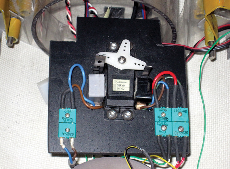
FIGURE 8.
Speed Control
The speed control presented a unique dilemma and caused issues that were difficult to figure out. I have used a very nice Msonik reversible speed control in the past and had great plans for it on this new project. The ol’ reliable Msonik 15 amp 12 volt speed control burned out. Here’s where the large and the beautiful 12 volt Pittman motor came into play.
I had another speed control from a former project and decided to try it. I figured out that the large Pittman motor was drawing too much amperage and would slowly burn out the low amperage Msonic speed control. A speed control, after all, is a form of radio-controlled variable resistor and will not allow an unlimited amount of amperage to pass through it. The large Pittman motor drew too much amperage. The larger speed control was rated at 33 amps and worked fine. The larger speed control didn’t have a reverse function, however, I needed to create one. I had no budget for this, so I figured I could use a relay to reverse the motor.
I bought a 10-pin heavy-duty spade terminal relay known as the “ice cube” (see Figure 9) from the local electronics supply store.
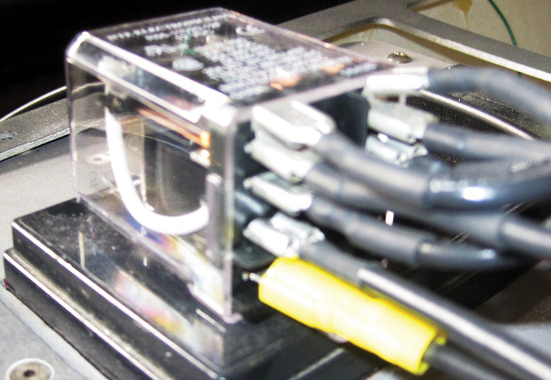
FIGURE 9.
I crossed the leads to the movable relay flipper so when the relay is switched, it would reverse the polarity leading to the motor, thus reversing the motor rotation direction. The motor reversing servo is depicted in Figure 10.
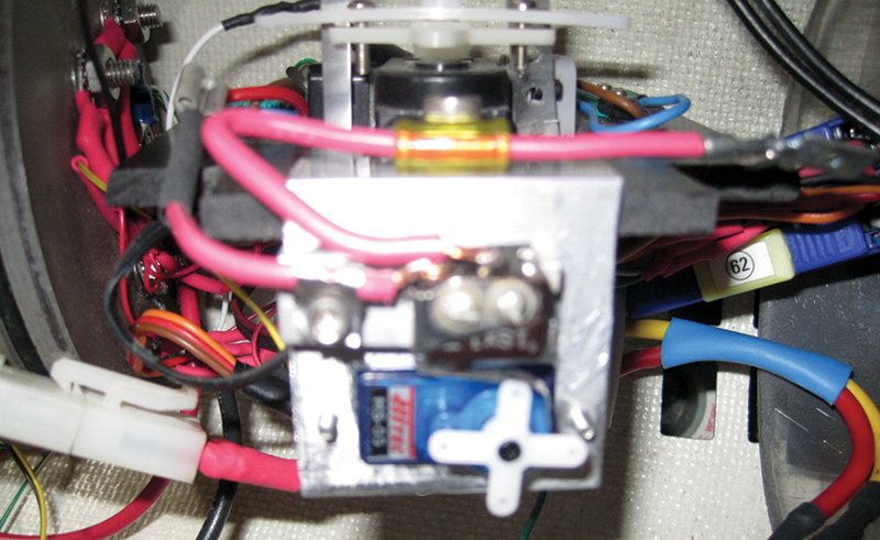
FIGURE 10.
This works so well that in operation it can be switched, and instantly the motor reverses. The voltage was still 12 volts but the amperage push needed was much greater than the small electric motors I used before. The speed control — as well as the receiver and compressor switches — is located in the small electrical chamber in Figure 11.
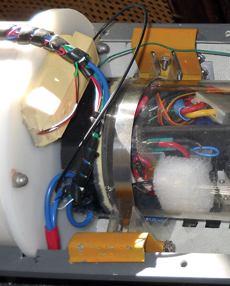
FIGURE 11.
The motor reversing relay is located in the ship’s bow due to lack of space in the central electrical box. Figure 12 shows the relay’s water-tight chamber in the bow; Figure 13 displays some work in progress details.
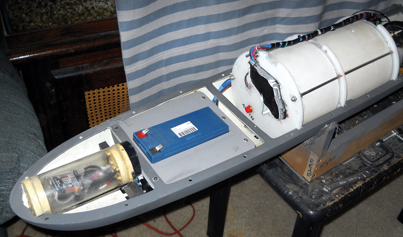
FIGURE 12,
FIGURE 13.
Potting Procedure
Anytime someone constructs an electrical device or electrical wiring into a system where it will be exposed to a lot of water or wetness, the electrical components need to be sealed. This process is called potting. There are a lot of potting compounds. To seal off the ends of the bulkheads (which are the connecting points of my electrical wiring), I used a potting compound recommended by and obtained from a company called Epoxies, Etc. The black liquid seen in Figure 14 is the first step in the potting procedure of the electrical box at the hull center which contains the speed control and receiver. I poured in a small amount first to see if my protective fencing leaked or not. Figure 15 shows the completed potting process.
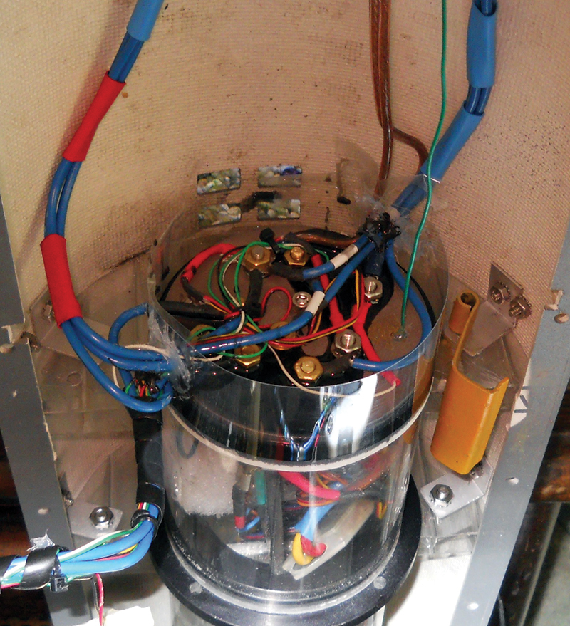
FIGURE 14.
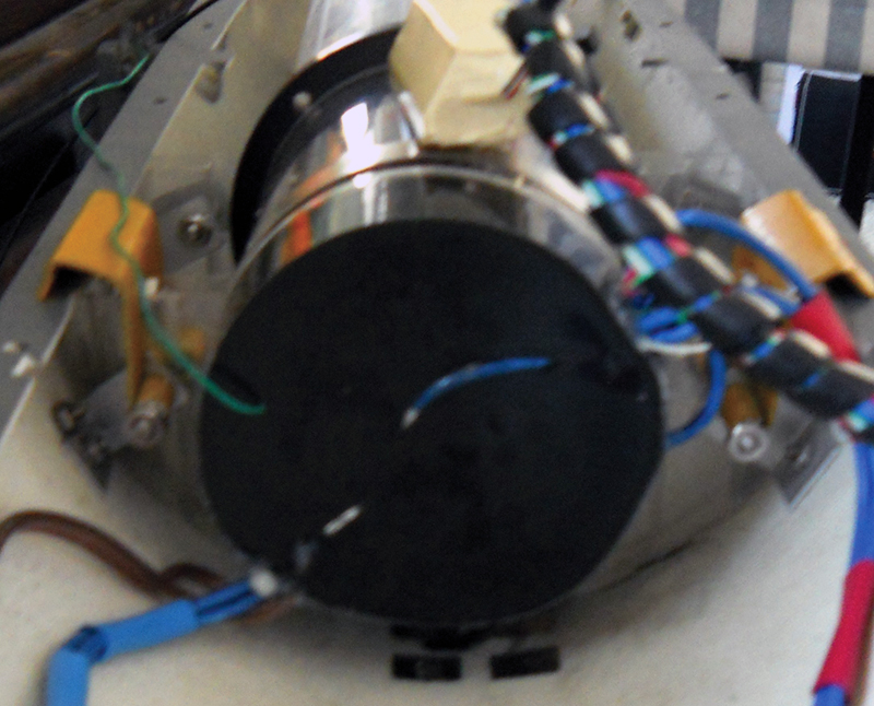
FIGURE 15.
Radio Transmitter Power Pack
My submarine has a very nice 12 volt battery similar to a small motorcycle battery. This can run the low wattage components for a long time. The transmitter, however, has a very small nine volt battery in it and has a short life span. However, I had a revelation one day to use a 12 volt battery to also power my transmitter. I wired the 12 volt battery into my transmitter with a transformer to step down the voltage to match the nine volt system in the transmitter.
On a visit to my local electrical supply store, I discovered they had a power pack with an adjustable regulator on it that was just what I needed. I hacked my radio transmitter by cutting off the electrical cord to the battery and constructed a plug which connected to the power pack. Figure 16 shows my solution to the transmitter problem and the rechargeable power pack.
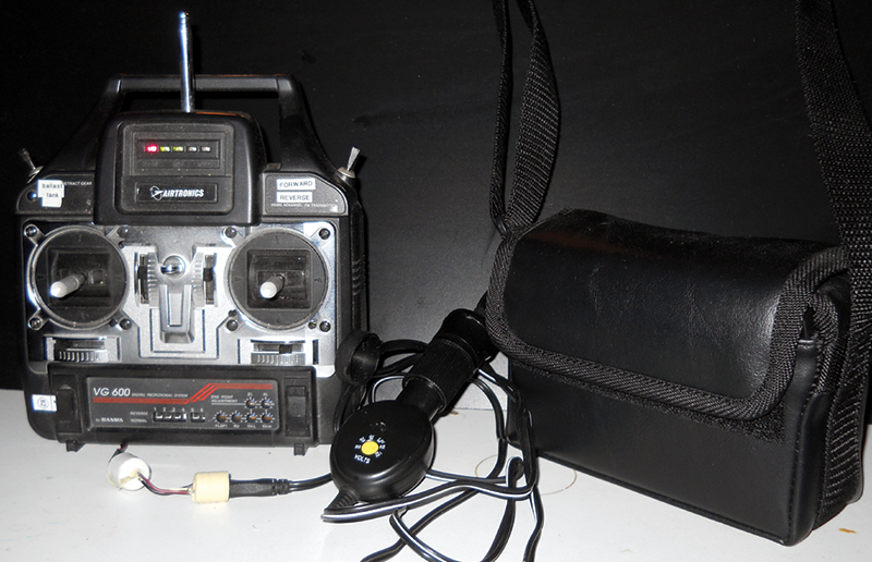
FIGURE 16.
The funny little plugs that connect the transmitter to the power pack were cast in hard urethane plastic like the rudders. My estimate is that this system upgrades the transmitter reserve power to 1,000%. Another feature you might like is the fiber optic onboard battery capacity indicator.
Fiber Optic Indicator
I had to know the charge level in the submarine battery. I found a printed circuit board designed to indicate with three colored LEDS (light emitting diodes) the charge level in a 12 volt battery. This small board has a red, yellow, and green LED which I connected to some fiber optic lines to the sail top to enable me to see the charge level by bringing the sub close by to check it.
Figure 17 shows the underside of the sail and the encapsulated indicator chip super-glued to the underside of the sail. The chip itself is at the left for reference only. The fiber optic lines exit the top of the sail as seen in Figure 18. I cast the chip into hard urethane plastic to seal it from moisture. (Had I known about the potting compound I talked about earlier, I would have used it in this application.)
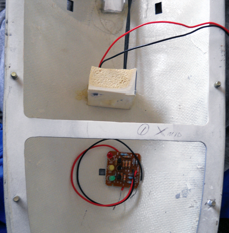
FIGURE 17.
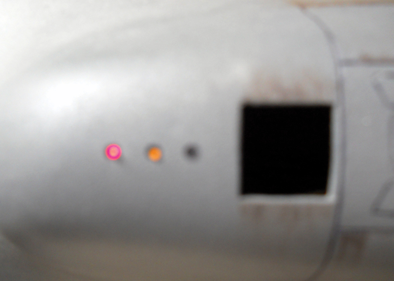
FIGURE 18.
Water Sensor
To detect the presence of water in the air compressor chamber, I made a very basic water sensor. This is simply two electric lines held at an established distance from one another, then connected to the 12 volt battery. This sensor sits near the bottom of the water-tight chamber housing the air compressor. The water sensor LED leads to another fiber optic line to the sail exterior.
Electrical Schematic
The electrical schematic in Figure 19 gives you an idea of the real over-all complexity of the system, and what I had to deal with when one function or another wasn’t working. This overall electrical configuration followed a simple rule: “If it works, it works.” I designed this system on-the-fly and drew it up later.
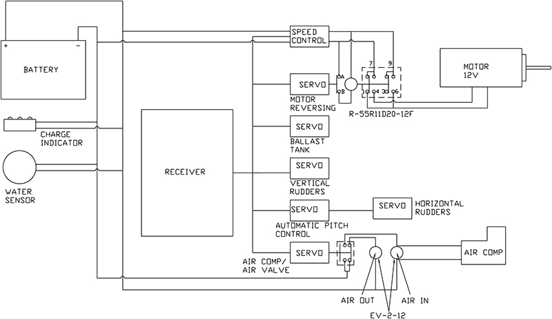
FIGURE 19.
Conclusion
The sub went through final setup in a home-built test tank located in the basement. This required many hours balancing the final configuration with lead and closed-cell foam. Eventually, I perfected the submarine’s balance by forward and reverse movement until the lower rudder wouldn’t touch the bottom of the shallow test tank.
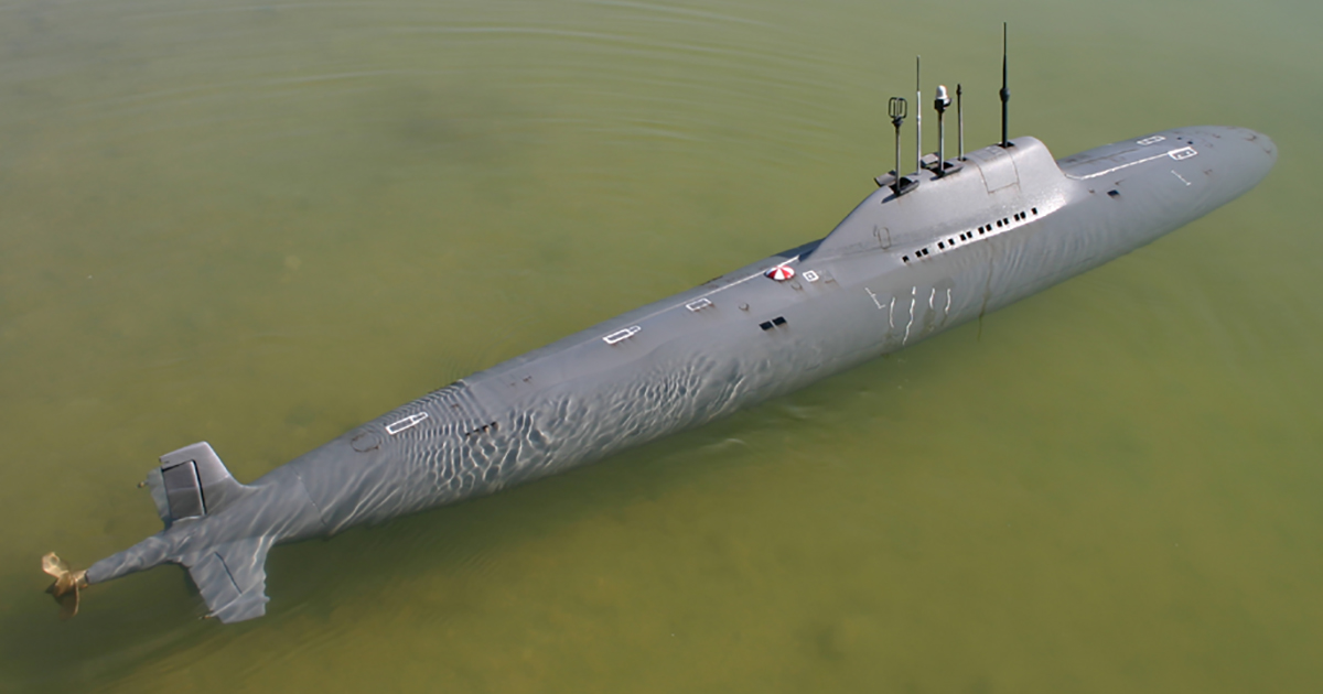
For 10 years I worked and moved forward each day with this project. There are times I look at it and wonder whether I should attempt to make some improvements or do some changes here or there. However, I look at it with pride. My submarine now maneuvers on the clear waters of Japan, England, and France. How much further it will travel, only time and my imagination will tell. NV
If you would like to correspond with me regarding this submarine build, you can contact me at [email protected].