I like the look of seven-segment LED displays and came up with a couple of fun applications for them: a scrolling display of the digits of pi (3.14159…) and my own desktop version of the National Debt clock. The five-digit Freescale MC14489 can be daisy-chained to support displays of more than just five digits, so I settled on stringing three of them together for a 15-digit display. This is long enough to give a pleasing appearance when scrolling, and to display all the digits of the national debt (at least for now). This is a versatile system which can be adapted to plenty of other uses, too.
Coding and Math
My original plan for the scrolling pi display was to use a PIC microcontroller to actually calculate the digits prior to displaying them. There are some fairly sophisticated formulae called “spigot algorithms” (see sidebar) available which can calculate each successive decimal digit without having to calculate the previous digits. It looked like they could be converted into PIC code. I found that my math skills weren’t sufficient to get these algorithms to work (even in a spreadsheet), though, so I never got to try to write the PIC code. Instead, I settled for downloading the first 1,100 or so decimal digits of pi and storing them in the PIC which displays them in a loop. The pi data is stored in the PIC’s Flash memory during device programming with the POKECODE instruction (take a look at the source code file in the downloads). Be careful not to overwrite the program code!
The math for the National Debt clock is very straightforward — all we need to do is look up the current amount of debt and the rate of increase, enter them into the PIC, and then keep a running total with time. This information is available at https://usdebtclock.org/, among other places. Take a look at the PICBASIC PRO code (listing available in the downloads) and the embedded comments to see how a 15-byte array variable is used to hold either the pi digits or the national debt value. Addition of the numbers for the national debt is done on a byte-by-byte basis within the array variable, carrying from one byte to the next as necessary.
Design
The MC14489 display drivers use a synchronous serial interface requiring three wires: data, clock, and enable. I selected a straightforward three-button user interface (up, down, and enter) to set the values for the National Debt clock. Since the display and the user interface are the only external interfaces for the PIC, a low pin count device is all that is needed.
I did want to store as many pre-calculated digits of pi in the PIC as possible, so I looked for a device with a fair amount of memory. The closest device I had on hand was a 16F819: an 18-pin device with 2K words of Flash. Other 18-pin devices with more memory (such as the 16F87 or 16F88) could also be used. The schematic is shown in Figure 1.

FIGURE 1. Schematic for the display.
I have omitted the LED displays for digits 1-5 and 6-10 for clarity, since they wire up the same as for digits 11-15. The user interface and MC14489 interface are on port B. This takes advantage of the available weak pull-ups on this port for the input buttons; it also reduces the parts count. The 16F819 has the option of using an internal oscillator and internal MCLR pull-up resistor which can free-up additional pins on port A. In this design, I have MCLR pulled up externally so the PIC can be easily reset. I am using the PIC’s internal oscillator to free-up I/O pins RA6 and RA7 for future use, and I set the oscillator frequency to 4 MHz by configuring the OSCCON register in the code. Several other I/O pins on port A and port B are available to add other functions, sensors, etc., to the circuit, or to interface the display module to external systems.
When you program your PIC, you will need to select the “INTIO2” oscillator configuration option to enable the internal oscillator. Note that not all programmer software uses Microchip’s standard name for this option; my software calls it “IntRC.”
The Build
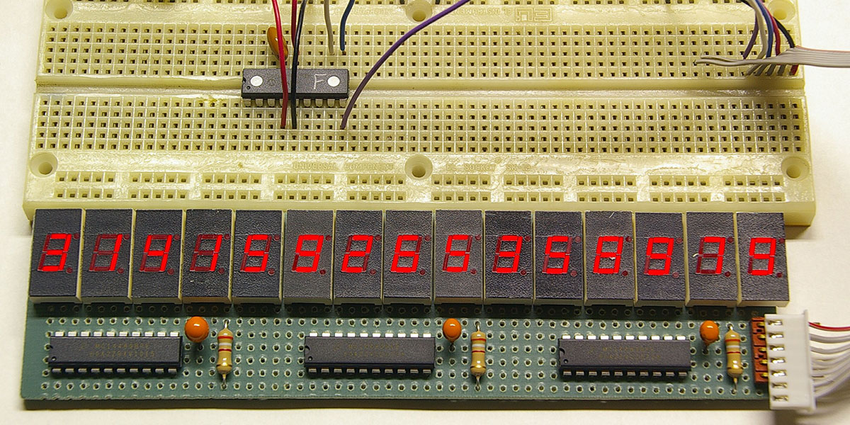
The MC14489 makes it very easy to interface a microcontroller with common-cathode LED displays, but there is still a lot of wiring needed to multiplex those displays and connect them to the drivers (Figure 2).
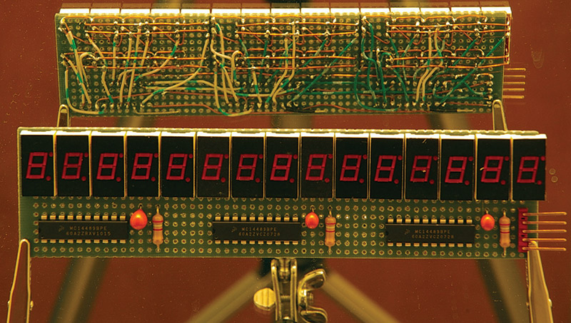
FIGURE 2. Front and back of the prototype display; note the rat's nest of point-to-point wiring.
This is clearly a project that needs a custom printed circuit board (PCB) to be practical. I like ExpressPCB’s mini-board service because it’s very reasonably priced, but the fixed board size (3.8” by 2.5”) seemed too small to hold 15 LED displays plus the PIC and driver chips. After scouring parts suppliers to find small displays and dusting off my trigonometry skills to align them diagonally across the board, I came up with the board layout in Figure 3.
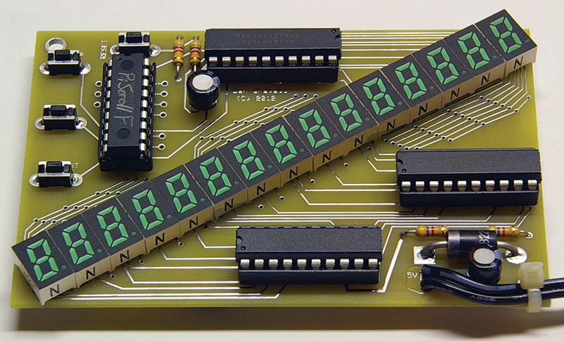
FIGURE 3. Layout of the PCB with a diagonal arrangement of the LED displays.
ExpressPCB doesn’t allow components to be placed at odd angles like this, so I had to create a custom pad array from scratch to fool the software into aligning the displays at the proper angle of about 31°. The displays I selected are made by Rohm; they come in several colors, and each LED display is only 7 mm wide with a character height of 8 mm or 0.31 inches. It’s a tight fit with a lot of curving traces around the displays but it works, and the diagonal line of displays complements the look.
I recommend using sockets for the four ICs to reduce the risk of damaging them during soldering. However, if you plan to mount the board behind a panel or in an enclosure, note that the height of the chips in their sockets exceeds the height of the displays themselves. The bypass capacitors can also be mounted horizontally to keep them below the plane of the displays. I have included extra pads on the unused I/O pins on the PIC so you can “roll your own” ICSP interface if you choose to solder the chips to the board (though you will have to add a diode between the MCLR pin and its pull-up resistor to protect the rest of the circuit from the programming voltage).
Scroll That Beautiful Pi Footage
The display defaults to scrolling the digits of pi on power-up (Figure 4).
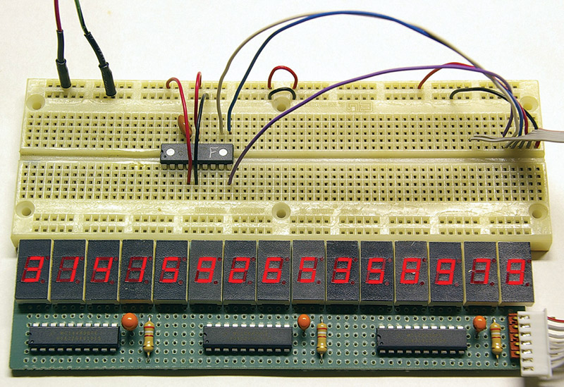
FIGURE 4. Displaying the first 15 digits of pi.
After scrolling all the digits, the display will pause and then restart from the beginning. If you press and hold the mode/enter button while powering up or resetting the PIC, the display enters National Debt clock mode.
First, you will enter the current value of the debt, starting with the most significant digit and using leading zeros as necessary. Select each digit with the up and down buttons, then press enter to adjust the next digit. Then, enter the rate of increase of the debt — in dollars per second — in the same manner.
Now, you can watch our debt pile up in near real time, or have a more relaxed experience watching pi scroll by. NV
Parts List
| ITEM |
DIGI-KEY PART# |
| PIC 16F819 microcontroller, 18-DIP |
PIC16F819-I/P-ND |
| (3) MC14489 five-digit LED display driver, 20-DIP |
MC14489BPE-ND |
| (15) Seven-segment common-cathode LED display |
Rohm LA-301xL series ("x" denotes color) |
| (4) Pushbutton momentary switch |
450-1665-ND |
| (4) 4.7K ohm 1/4 watt resistor |
|
| (2) 4.7 µF tantalum capacitor |
|
| 1N5401 diode |
1N5401-TPCT-ND |
| A PCB and preprogrammed microcontroller for this project is available in the Webstore |
SPIGOT ALGORITHMS
A spigot algorithm is a type of algorithm used to compute the value of a mathematical constant such as p or e. Spigot algorithms are unique because they do not require the total number of digits to be fixed beforehand, and do not require the computation of several intermediate results which are combined to produce the final result. There are two kinds of spigot algorithms:
- Those that can produce a single, arbitrary digit (also called digit extraction algorithm)
- Those that produce a sequence of digits, one after the other. The Bailey-Borwein-Plouffe formula is a digit extraction algorithm for p which produces hexadecimal digits.
A sequential spigot algorithm for p was produced by Stanley Rabinowitz and Stanley Wagon (this algorithm is sometimes referred to as “the spigot algorithm for p”). Spigot algorithms that produce a sequence of digits begin producing digits and produce them continuously, rather than waiting for the entire algorithm to finish. Spigot algorithms are known for p and e. Spigot algorithms typically work in a particular radix, such as hexadecimal or binary number. [From Wikipedia.]
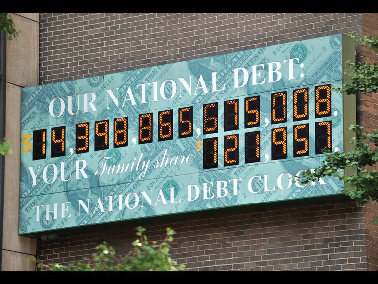
The National Debt Clock
The official National Debt clock is a billboard-sized running total dot-matrix display which constantly updates to show the current United States gross national debt and each American family's share of the debt. It's currently installed on the western side of One Bryant Park, west of Sixth Avenue between 42nd and 43rd Streets in Manhattan, New York City.
The idea for the clock came from New York real estate developer Seymour Durst, who wanted to highlight the rising national debt. In 1989, he sponsored the installation of the first clock which was erected on 42nd Street close to Times Square. At the time, the national debt remained under $3 trillion, but was rising. The clock was temporarily switched off from 2000 to 2002 due to the debt actually falling during that period.
In 2004, the original clock was dismantled and replaced by the current clock at the new location one block away. In 2008, the US national debt exceeded $10 trillion for the first time, leading to press reports that the clock had run out of digits.
The original clock outlived Seymour, who died in 1995, with Seymour's son Douglas taking over the responsibility for the clock through the Durst Organization. As of September 2009, Douglas Durst's cousin Jonathan "Jody" Durst — with whom he shares a co-presidency of the company — is in the process of taking over the day-to-day operations as president. In an interview with The New York Times, Jonathan Durst has said that maintenance of the clock is planned "for years to come."
Douglas Durst has been quoted as saying that the clock represents a non-partisan effort; he has further explained the motivation behind the project in terms of intergenerational equity: "We're a family business. We think generationally, and we don't want to see the next generation crippled by this burden."
According to Douglas, his father had been toying with the basic idea of drawing attention to the growing national debt since at least 1980, when during the holiday season he sent cards that said "Happy New Year. Your share of the national debt is $35,000" to senators and congressmen. In the early eighties (when Durst first developed the idea of a constantly updated clock), the technology required to implement the project was not yet available.
First Clock
With the national debt at 2.7 trillion, the original 11 by 26 foot (3.4 × 7.9 m) clock was constructed at a cost of $100,000. It was mounted a block from Times Square on a Durst building at Sixth Avenue near 42nd Street; it faced the north side of 42nd Street and Bryant Park across the intersection. Built by the New York sign company Artkraft Strauss, the clock featured a dot-matrix display with the then-typical character resolution of 5x7. Similar to the second clock, the updating mechanism was such that the display was set to the estimated speed of debt growth (odometer-style) and adjusted weekly according to the latest numbers published by the US Treasury. Up until the week before his death, Seymour himself adjusted the tally via modem. Since his passing, Artkraft Strauss has been keeping the figures current.
In 2000 — due to an improving debt situation — the clock started to run backwards. With the original purpose of the clock being to highlight the rising debt and the reverse giving a mixed message (and with the display not being designed to properly run backwards), the clock was unplugged and covered with a red, white, and blue curtain in September 2000, with the national debt standing at roughly $5.7 trillion. The clock was not dismantled, however, and in July 2002 the curtain was raised and the clock once again picked up tracking a rising debt, starting at $6.1 trillion.
Second Clock
In 2004, the original clock was moved from its location near 42nd Street; the building has since made way for One Bryant Park. An updated model — which can run backwards — was installed one block away on a Durst building at 1133 Avenue of the Americas (Sixth Avenue). It is mounted on the side wall of the building which faces West 44th Street. The new clock is outfitted with a dot-matrix display of higher resolution than its predecessor which emulates the customary seven-segment numeral patterns, allowing the numbers to be read more easily.
In the midst of extensive media attention during the financial crisis beginning in 2007, some news reports mentioned the National Debt Clock, highlighting the fact that its display had run out of digits when the US gross federal debt rose above $10 trillion on September 30, 2008.
An overhaul or complete replacement adding two more digits to the clock's display is being planned.
Similar Projects
The German National Debt clock is located at the Berlin headquarters of the taxpayer watchdog group, Bund der Steuerzahler.
The idea of conveying a message through a periodically updated clock found an earlier expression in the Doomsday clock. However, the innovation of the National Debt clock was to feature a constantly running counter; it has since inspired similar projects elsewhere, both in the US and further afield. Various tracking counters of national debt are also kept online.
The National Debt clock has been credited as the inspiration behind other running totalizers, for example, an AMD campaign employing an electronic billboard; instead of a debt, it tracked the supposed additional cost of using a rival chip.
For more details on this, visit Wikipedia.org.
Downloads
PCB and source code files.