We recently added a new kitten to our household. Little Chubby is adorable, but he is still learning what is off limits. We don't allow our cats (we now have two) on the tables, and this random rule seems to be hard for cats to learn since they love to jump up on anything that isn't their cat house. Our method of behavior reinforcement is shooing them off whenever we catch one sitting on a table. Of course, this method takes a long time since they might have been sitting there for hours before you catch them. They are also quite smart, often they hear you coming and jump off before you catch them in the act.
Solution
I thought this would be a great problem to solve with a new electronic project. I envisioned a small box that could be moved from table to table and would automatically enforce the rules.
The build constraints would be to construct it inexpensively and in a timely manner. This basically meant that it would need to be made from parts that were on hand since shipping things in from most places takes a few weeks.
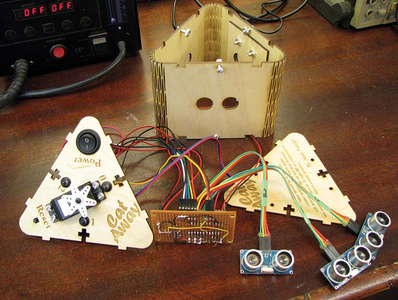
All the pieces.
Detection
My first thought was to use a motion sensor, but it would need to be placed in such a way that it wouldn’t send false alarms whenever we were walking around the table. Infrared beams were another idea, but it would require IR LEDs and IR transistors to be mounted in inconvenient places on the table. I guess if there was no time or real budget, a cool over-the-top method would to use a ceiling mounted Microsoft Kinect sensor to generate a 3D representation of the table and use software to look for a cat.
The optimal solution within budget was an ultrasonic sensor which could be set up so it is looking out across the table. Then, it could measure the distance between it and objects in front of it. This way, it can determine if the object is close enough to be concerned with or if it should be ignored.
Alarm Method
Once you have detected that the cat is on the table, you need to scare it off. There were three motor types that were considered: a gear motor, a servo motor, and a stepper motor. All would have done the job, but some would have taken more work.
The gear motor would turn slow enough and have enough torque to turn something like a small doll (my cat version of a scare crow); the issue is that the gear motor can stop at any location and would need some type of index sensor to allow the actual position of the doll to be known. This is required since the arms of the doll could possibly cover a sensor if it came to rest in the wrong rotational position.
The stepper motor was ruled out since when powered down, it could be turned out of position. So, even if it didn’t lose any steps during operation, a true starting position would still be needed. The servo was selected because of its simple wiring requirements and that no external position sensor was required
The servo can easily be commanded to move to a certain position, and it works quickly and reliably. Best of all, only three wires are needed: 5V, ground, and a signal from the microcontroller.
A second alarm method for easily adding different scaring abilities is a 12 volt alarm output. With this output, you are no longer limited to the movement (and sound) of the servo. A loud 12 volt buzzer or vibration motor would be a simple addition to the system to guarantee results.
Project Box Selection
The design was going to be stuffed in an off-the-shelf project box, which meant it would have four sides. So, it would need four ultrasonic sensors. I thought this would be a bit of overkill since cats usually snoop around for a bit before they settle down for a rest on the table. In my mind, I was thinking three areas of detection from a box mounted in the center of the table would be ideal.
The only issue with that is I have never seen a triangular project box and I certainly didn’t have one on hand. The plan to expand the build to a custom enclosure was made so that three sensors could be used.
Circuit
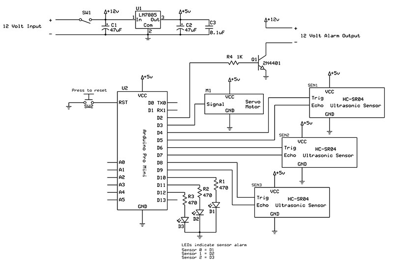
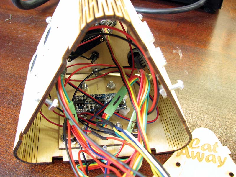
The heart of this project will be the microcontroller. Since the task isn’t complex, almost any microcontroller would do. The main thing I was concerned about was that I had enough I/O pins to handle everything. I chose the Arduino Pro Mini since I had some on hand, I love the small size, they have a ton of I/O pins, and the price is such that you would simply use a new one for the next project rather than scavenge one from an old one.
As a bonus, this microcontroller is programmed using an FTDI cable which makes it very easy to do serial port debugging. The HC-SR04 ultrasonic sensors have four connections: two for power; a trigger; and an echo pin. The trigger and echo pins are connected to the microcontroller to be able to initiate a measurement and get the results.
There are some ultrasonic sensors such as the Parallax PING))) that require only one I/O pin. So, if I was I/O constrained, the Parallax version could be an easy way to lighten my I/O needs.
Next, we have three LEDs that will be used to indicate which sensor was triggered. These three blue LEDs will be driven directly from an I/O pin since they will only draw around 4 mA with the 470 ohm current-limiting resistor. The LEDs and resistors are shown as individual components in the schematic, but I ended up using some that were pre-built with the resistors soldered in place and leads attached.
Cat Away! schematic.
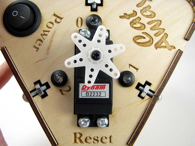
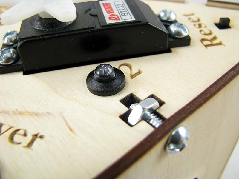
The servo will use just one I/O pin to receive the position information it needs. The servo was selected such that it would have enough torque to spin something fairly heavy. The Dynam B2232 that was used has a torque of 44.4 oz-in at 4.8 volts. The use of a servo motor meant that using the voltage regulator that is built into the Arduino Pro Mini would be out of the question, and that a stand-alone voltage regulator would be needed.
The "twirling" thing.
The power supply section is very simple. A 12 volt DC plug-in power supply will give power to the box using a barrel connection; a LM7805 in a TO-220 package along with three filter capacitors will be used to generate the five volts for the electronics.
A power-on switch will be wired in series with the power-in and the feed to the circuit so that the circuit can be powered down completely when needed.
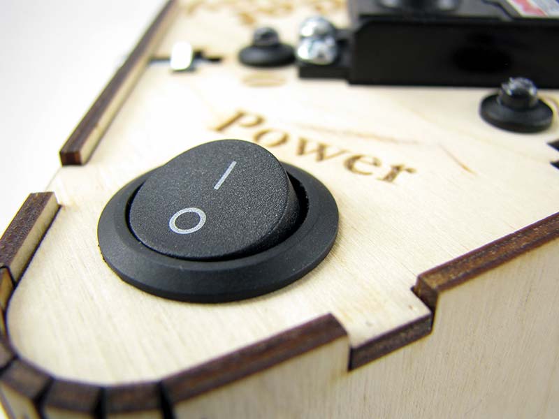
Power button.
The 12 volt alarm output is buffered using a small 2N4401 NPN transistor in a TO-92 package. This allows the five volt low current I/O output from the microcontroller to control external items such as a vibration motor with ease. There is no current limiting on this connection, so a short on this external alarm output would blow the transistor. A simple current-limiting circuit could be added with a few more components.
One method that would probably be fast enough would be to insert an inline current sense resistor to the output and use this as feedback to an I/O pin that is capable of being interrupt controlled. Select the resistor value such that the current you are wanting to trip the over-current at will be high enough to be seen as a digital high. The interrupt routine would simply turn off the output transistor’s base current to shut things down. Nothing was done with this, though, to keep things nice and simple.
The Arduino Pro Mini has a reset pin on the printed circuit board (PCB).

Reset button.
This was tied into a momentary N/O pushbutton switch that can be pressed to reset the system. This is used after the system has detected something with one of the three sensors and is now indicating which sensor caused the alarm using one of the three LEDs. The RST line on the board needs to be pulled to ground briefly to reset the microcontroller. The physical connection to this option was very convenient since the RST and GND pins are side by side.
Firmware
The code is very straightforward for this project. The hardest thing in this project is in the multiple ultrasonic sensor readings. However, this was made simple by using an Arduino library called NewPing by Tim Eckel (http://playground.arduino.cc/Code/NewPing).
A setup routine configures the hardware such that the correct pins are inputs and outputs. The ultrasonic sensors are then pinged one after another in the main loop. Once a new set of measurement data has been collected, the pingDataComplete function allows us to determine if any of the sensors fall within the alarm zone. If one does, we sound the alarm to scare off the cat and turn on the indication LED which corresponds to the sensor that caused the alarm. If all of the readings are normal, we just move on and take another round of readings.
During the alarm phase, we move the servo motor back and forth. Normally, you would code a PWM out to the servo so that it moved to the desired position. Another Arduino library has made this very simple. The servo library (http://arduino.cc/en/reference/servo) lets you take full control of the servo with just a few lines of code. Programming with some of these powerful libraries feels a bit like cheating if you are used to doing things the hard way, but I will take all the help I can get to speed up project building!
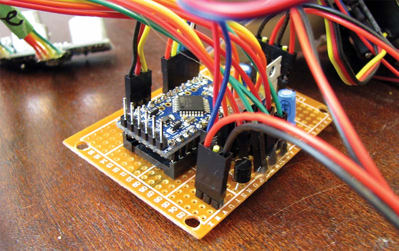
Building the Proto Board
I struggled with the decision to breadboard the circuit first or just move to a perfboard since it was so simple. I have been bit by that in the past, so I ended up breadboarding the circuit first to true everything out.
When making the permanent perfboard version, 0.1 inch breakaway headers were used to allow the entire thing to be modular. Of course, this can easily let out the magic smoke if a cable is plugged in backwards or into the wrong place. However, the benefits are ease of assembly and any troubleshooting that may be necessary.
Point to point wiring was used to connect everything together on the back of the perfboard. Many of the headers were placed such that they just needed to be linked to adjacent pins, reducing the chances of any shorts from crossing wires.
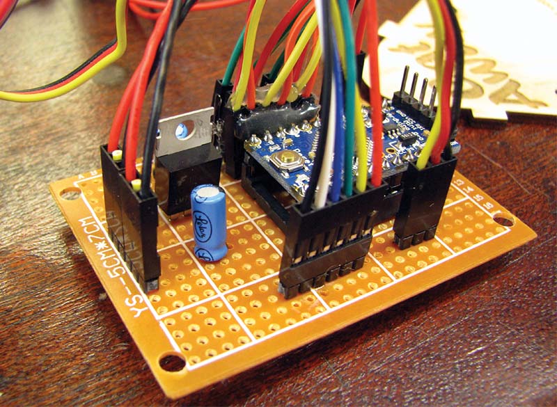
Board setup.
Designing and Building the Housing
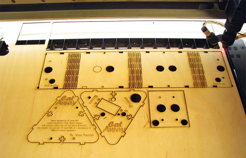
As mentioned before, the triangular housing requirement meant it would need to be custom. Thankfully, the days of cutting plywood using a table saw for project boxes is over. A small CNC machine and laser cutter are now options. I opted on using the laser cutter since it is more precise, less messy, and would create something that would be strong enough for this build.
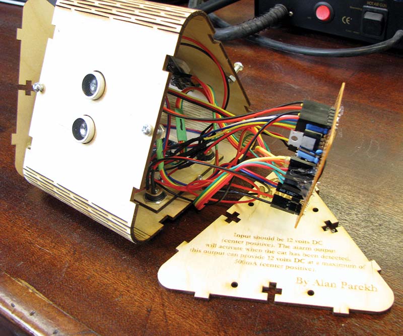
The internals.
Initially, I was thinking of using 3 mm black acrylic for the design. The intersections of the three faces would be linked together using some shallow finger joints (just to keep the edges aligned), and a top and bottom section would use some T-slot connections that would allow nuts and bolts to hold everything together. I could just imagine the language I would need to use when assembling the thing, though.
I am sure the three side pieces full of electronics would not behave while I was trying to align and screw down the top and bottom of the housing.
I remember reading some articles about a laser cutting plywood in such a way to allow it to bend. Google “laser cut plywood bendable” for more information on this technique
Laser cutting.
I had some 3 mm mahogany and some 3 mm baltic birch plywood, so I gave the process a try. The results with the mahogany were not great. It seems inherently stiffer than the birch.
After two or three design attempts, I had the birch bending like a limp noodle. The box design ended up being a long 39 cm strip that had three bendable joints cut into it so that it could be formed into a three-sided box.
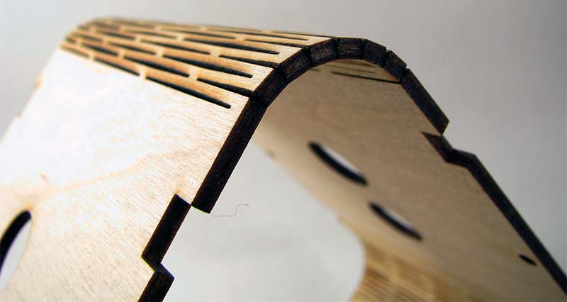
Rounded corner.
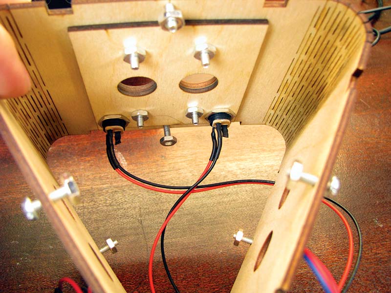
The back side of the box comes together in the center and is held tight using a small plywood brace and four nuts and bolts. The only holes that are cut into the long strip (other than 10 small bolt holes) that makes the walls are six holes for the three ultrasonic sensors to poke out of, and two holes for the power input jack and alarm output jack.
The HC-SR04 ultrasonic sensors have four very tiny 1.4 mm mounting holes in the corner of the module. I didn’t have any nuts and bolts this small, so I opted to simply use double-sided foam tape to hold them in place. This tape is crazy sticky, so it won’t release unless you are deliberately trying to remove a sensor.
I think if I was going to spend a bit more time on the design, I would have built a support bracket that would hold the sensor board from the rear. The front has a crystal oscillator near the top, and the back is full of surface-mount electronics along with a 90 degree angled header, so foam tape would still be required as a spacer. The outer sticky portion could be left covered so it would be easier to work with, and then the sensor would not be able to be pushed in even with lots of force.
It took quite a bit of trial and error to get the perfect radius and triangle size for the upper and lower panels. After the first two or three didn’t quite fit, I changed from plywood to cardboard until it finally came out, matching the curves of the bent corners exactly. The top and bottom are each held in place with three T connections; once tightened, they hold everything in place very well.
I'm not sure how well it would hold up if I dropped it off the table, but it has a nice solid feel in the hand. The laser machine has the capability of etching onto the wood. This was used to etch in some identification information, as well as the project name. Getting the etch power just right so that the results are nice and dark takes some playing around, but thankfully baltic birch plywood is quite consistent.
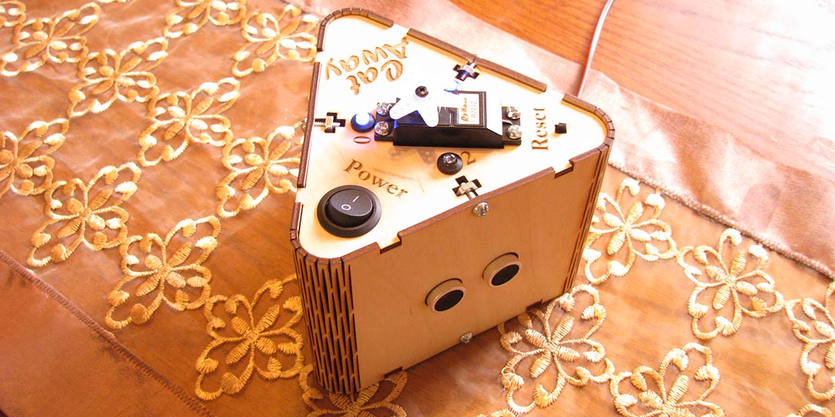
There is actually quite a large number of items mounted to the top of this box. We have the on/off switch, a reset switch, three LEDs, a servo motor, and three slots for the T-slot nuts and bolts. I wanted the servo horn to be centered in the design which dictated where a lot of the other items needed to go.
Screw nut.
The servo motor is held in place very securely using four nuts and bolts; the power switch and LED bezels are a simple press-fit design. The reset button was the only item on the top of the box that would have been better if I had a panel mount style momentary switch. The switch that I used is meant to be a replacement switch for computer reset buttons. These switches are snapped into a housing and have a button cap that presses it.
It's mounted to the underside of the top panel using some hot glue, and has the switch shaft poking up through the top about 3 mm, which isn’t too bad. Thankfully, the switch throw is only about 2 mm before it activates.
The bottom panel doesn’t have any holes cut into it other than four bolt holes for the perfboard to get mounted. Turns out a rectangular perfboard is not that simple to fit into a triangular base since there are mounting screws as well as the power input and alarm output jacks in close quarters. The perfboard is held off the bottom panel using 1/4 inch nylon spacers so that none of the solder connections are in contact with the case. It also allows for just enough space for the lower rear mounting screw to be inserted.
Testing It Out
I tried the project out with the servo disconnected so it wouldn’t alarm the cats during testing. I wanted to see how well the ultrasonic sensors worked with a furry cat compared to the piece of cardboard I was using during testing. It was a bit of an afterthought that there might be a problem since I was just dealing with the sensors as magic boxes. However, in reality, they are sending out a burst of sound (above the human hearing range) and waiting for it to bounce off an object and return.
One of our cats looks like something you would see on the end of a boom mike (called a dead cat in the industry!) when they are being used outside to filter out wind noise. I was worried that the long haired cat might have a genetic way to bypass detection. Turns out the sensors work great in detecting both cats!
I set it up on the table without anything on the servo and waited to see what the reaction would be. With a few treats left on the table, the long haired cat (not the kitten) made a fast retreat when the servo started moving around.
When set up on the table, I was able to walk around the entire perimeter without being detected. There is a variable in the code called tripDistance which might need adjusting if your table needs a detection range greater than or less than the 40 cm that is default in the code.
Future Upgrade Possibilities
Some future changes that would enhance the functionality would be to mount a piezo buzzer or some other type of loud sounder directly in the box. One could be plugged into the alarm output jack, but it would be nice to have this functionality built in. Currently, there is only a single variable in code that sets the detection range of the sensors. This works great if it will just be used on a single table size that’s round like my situation.
A simple code change would allow for sensor 0, 1, and 2 to have different detection ranges. This would allow it to work better on oval tables, for example. This would introduce another obvious enhancement requirement, though. You would need to remember exactly where to place it so that all three sensors line up to the programmed sensor distances. None of these problems exist when using a nice round table.
The way to make that work the best would be to not only have three separate detection distance variables for the three sensors, but to also allow them to be programmed in place. This could be accomplished by adding a new switch to the system.
When the switch is pressed, the system would make note of the closest distance it measures from all three sensors. You would simply walk around the entire table so that the system could record the safe distance. When put back into run mode, subtracting 5 cm from these new values would give you a great baseline for the system to have optimal detection.
Now that I’ve “tabled” this project, maybe you can think of some other useful applications. NV
Parts List
| ITEM |
DESCRIPTION |
QTY |
MODEL# / NOTES |
| U` |
Five volt regulator |
1 |
LM7805 |
| U2 |
Arduino Pro Mini |
1 |
Five volt 16 MHz version |
| For U2 |
24-pin wide DIP socket |
1 |
Optional if Arduino is to be socketed |
| SW1 |
On/Off switch |
1 |
|
| SW2 |
Momentary N/O pushbutton |
1 |
|
| C1,C2 |
47 µF 25 volt capacitor |
2 |
|
| C3 |
0.1 µF 50 volt capacitor |
1 |
Any voltage rating over 10 volts is fine |
| R1-R3 |
1/4 watt 470 ohm resistor |
3 |
|
| R4 |
1/4 watt 1K ohm resistor |
1 |
|
| Q1 |
NPN transistor |
1 |
2N4401 |
| D1-D3 |
5 mm blue LED |
3 |
|
| For D1-D3 |
5 mm LED bezel |
3 |
|
| M1 |
Servo motor |
1 |
Dynam B2232 |
| SEN1-SEN3 |
Ultrasonic distance sensor |
3 |
HC-SR04 |
| Circuit Board |
5 cm x 7 cm perfboard |
1 |
|