These days, we see many forms of ready-to-go development platforms such as the Arduino and Raspberry Pi which are primarily SMT component based. Not long ago, if you wanted a similar device you would build it using a copper clad strip board. One manufacturer of these prototype boards is Vero (www.verotl.com).
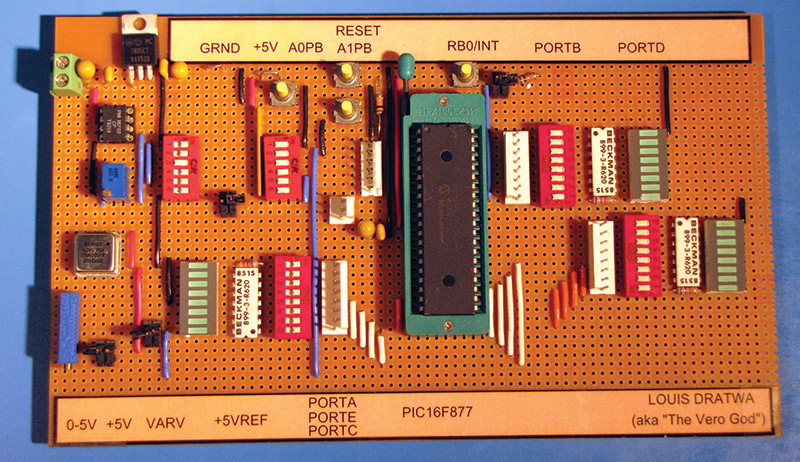
Many techs of yester year built their projects on a breadboard, then would transfer everything to a mirror copper clad board. I built a development Vero board project (Figure 1) based on the Microchip PIC16F877A-04 10 years ago. Most PICs are still available in through hole packages, along with common transistors, diodes, and resistors.
Having been an electronic technician for over 30 years (and still employed today), I have built countless Vero board circuits for both protyping and functional every day use. My experience using Vero boards has helped me be a better printed circuit board (PCB) layout designer. I recommend you give these timeless techniques a try.
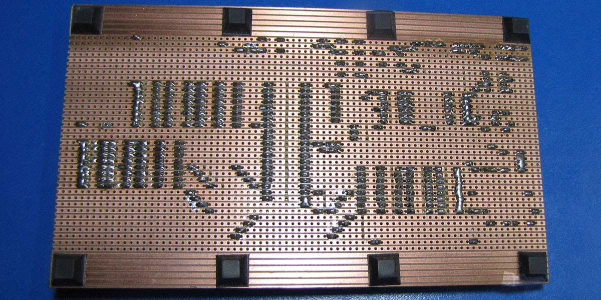
TOP
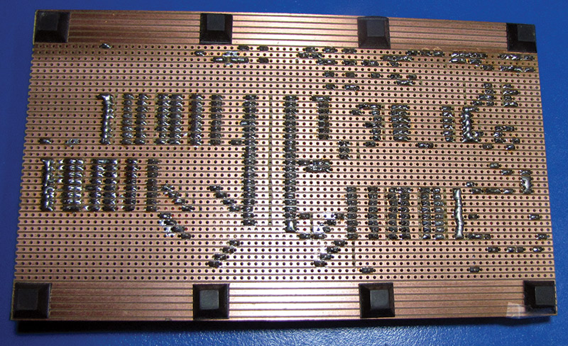
BOTTOM
FIGURE 1. This is how a Vero board ought to look! Top and Bottom
Vero Board Type
I prefer the Vero board type 01-0014 because it has 38 rows of traces with standard .100 inch hole spacing to accept many common electronic packages. It does not match a breadboard exactly, but it is close enough and offers larger sheets than breadboard strip boards. There are also five solid traces along two edges that can be used as power or data buses. These traces can be drilled to accommodate larger size connectors such as .156 IDC (insulation displacement connectors) headers.
Planning for Proper Space
Having the proper amount of real estate available is the number one consideration when planning a Vero project. Too many Vero projects quickly turn into a crowded nightmare because of poor planning (Figure 2). You can also have problems from not “proving” your circuit on a breadboard first.
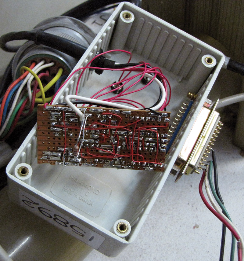
FIGURE 2.
This step gives you a ball park as to the space required for your project, so helps reduce rework. Don’t be afraid to rearrange parts if necessary. You may want to tack a couple of pins down on items like IC sockets, then look if it fits your plan. A good practice is to align all (or as many) of the ICs in the same orientation; this leaves no doubt which way an IC is to be installed. Stay away from leaf IC sockets as they have too many intermittent problems; only use machine IC sockets.
I always give ample room for my projects first and foremost because you or some else may have to troubleshoot and repair the strip board circuit. Secondly, I like to leave extra space for what I call the ECN space. ECN stands for engineering change notice and in my particular line of work, it is prudent to accommodate for this possibility up front. We might have a new variant or an old test that could require improving; this forethought makes changes easy to incorporate.
To help service your Vero creation, it is advisable to create a pictorial parts layout diagram along with your schematic. It can be a simple handdrawn figure or one created on a CAD program.
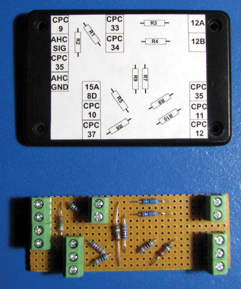
Pictorial example.
Wiring Vero
Typical wire used for Vero work is solid 22 gauge. Use at least three colors; for example, red, black, and blue (or any other colors). I use more colors if I need to differentiate analog from digital signals, or for different inputs, outputs, and voltage levels.
A good tip here is to strip one end of the wire, place it in your first hole, run the wire across to the target hole, then dent the insulation with your thumbnail above the hole. This helps stripping the wire at the proper length the first time, and will result in nice tight straight wire lines.
A pair of handheld auto wire strippers helps with large projects, plus gives the wires a clean cut look.
I recommend never running wires or placing components underneath the Vero board because it’s a lot easier to just look at the top when doing any troubleshooting. However, this rule can be broken to accommodate items such as .156 headers soldered onto the ”strip edge” which will need wire to bring the connections to the through hole traces underneath.
A tip here is to use the middle solid trace (for mechanical stability). Place the .156 header on top of the copper and scratch its pins into the strip. Use a Dremel drill (a drill press helps big time) and create the required number of holes from the copper side.
Next, you will have to make opens between each pin, but leave enough copper for proper soldering. You may want to remove the first solid copper strip towards the hole strips to prevent any shorts when soldering the wires on to the header. Do not use solid wire with IDCs or for anything “off board.” If the board needs work, just flexing the solid wire to get underneath can cause it to break open.
Soldering/Cutting Vero
Before soldering any device, ensure the copper clad side is fresh and bright. If it is dull and oxidized, use an ultra-fine grit sandpaper to restore it. Strip board is tricky to desolder as the drilled traces tend to lift if too much heat is applied. To avoid this, always use a wet solder tip to conduct the heat quickly when soldering or desoldering.
It is always tempting to bridge over adjacent traces or pins that require connecting when the opportunity arises. Do not go down this road! If rework is required, you may unsolder a connection without realizing it, which will result in wasted time and possibly never getting the board running. If you need to connect adjacent traces, use a bare wire on the component side bent for this purpose.
With more experience, you can leave the small piece of insulation on, but the solder heat has to be perfect because too much will cause the insulation to melt off. There is little metal available to wick away the heat. You may want to make an access point using a raised loop of wire for monitoring power or signals. Vero sells premade loops with colored beads if you want to get fancy. On that note, you may want to use an inexpensive through hole component bender for a more esthetically appearing project.
To keep a nice finished edge when cutting Vero board, always score both sides and align the break with a square table edge; then snap it off. Scoring only one side can result in an uneven break, creating two unattractive pieces of board.
Screw Terminals vs .100 IDCs
It is desirable to use screw terminals for power and any critical measurements since .100 IDCs are not designed for high current. You will find that a typical screw terminal block has pins slightly larger than the Vero board holes.
A tip here is to use a drill bit just a size or two larger than the holes; attach it to a Xacto™ knife tool and hand drill each hole to the desired size.
For serviceability, it is great to have all the connections to the Vero board removable, although this might not be practical in some applications. The .100 IDCs are great for LEDs (use integrated LEDs if possible), pushbuttons, connecting logic levels, and to aid in keeping the Vero board removable from all of its wires. IDCs should be avoided when small voltages are used or measured as the contact resistance can cause problems.
High Current Devices
High current devices can be accommodated by beefing up the copper traces with solder. Of course, you must take care not to short out adjacent traces. I’ve seen almost invisible solder strands short traces out. It is a good practice to run a small slot screwdriver between the traces, followed by a hard brushing of the finished solder side with a stiff horse hair brush. Of course, give it a visual check for shorts, cold solder joints, missed solder connections, and areas that should be beefed up with solder but were missed. It is also a good practice to “ohm out” power for shorts. Do all of this before powering up for the first time.
When calculating a fuse size for your project, consider all high current devices and current surges. Incandescent bulbs will produce a current surge until the filaments heat up and offer resistance. The use of a slow blow fuse here may be required. For most of my Vero projects, I use poly switches in place of fuses, as they reset themselves and do not require replacing if the current rating has been calculated properly.
Creating Opens
Just as important as a good connection is a proper open trace. I have seen some opens created by a space barely wider than an Xacto blade thickness. These may work at first, but as the Vero ages it shrinks. So, what was an open is now a bothersome intermittent headache.
When creating an open, I recommend removing one hole width of copper. Smaller widths will work but are not as visual or consistent when compared to removing a “whole” hole width.
The use of a two- or three-pin header gives the option of selecting which function you want by using a .100 shorting clip. I typically use four two-pin headers on my Vero development boards; here, one selects between Port B0 and INT (Interrupt). Other uses could include selecting whether an input is pulled up or down.
Mounting Vero
Mounting Vero board in project enclosures can be accomplished by custom cutting it to a size that will fit the circuit board receiver slots inside the case. This makes it easy to remove for servicing. Be sure to use the proper size case to avoid a crowded Vero board circuit (refer again to Figure 2). Other methods include using standoffs and drilling holes to accommodate them.
If you’re not using the five solid traces on the edge, this is a good place to drill the holes. Some designs are too small and one must drill the hole traces for mounting. Remove enough copper so nothing shorts to the standoffs, and don’t drill too close to any edge. You would think this is a clear concept, but I have seen many Vero problems from not addressing these issues properly.
In-Circuit Serial Programming
If I built this particular Vero board project today, I would add an ICSP (In-Circuit Serial Programming) five-pin IDC header for downloading source code. All of my PIC16F877A-04 based PCB (printed circuit board) projects have this feature which is connected to a DB9 connector on the chassis of the project.
That’s a Wrap
There are many opinions about when, where, or if to use Vero vs. designing a PCB. The majority of negative experiences involving strip board use originate from the lack of skill creating the strip board circuit. If built properly, a Vero board design can be just as reliable when compared to a PCB.
It is important to follow the guidelines presented here, however, being flexible and adapting to new situations is important too. This may require ignoring a rule or practice to build the best possible Vero board circuit. NV
Timeless Tips
The mating connector to an IDC header requires a special crimp tool to connect stranded wires to it. A work-around is to solder wires directly to the IDC connector. It should be noted that even with the crimp tool available, there are cases where it is advantageous to solder wire directly to the connector. It takes a fine conical solder tipped iron, and you must be careful how long you apply heat and solder. Too long of a time could result in melting the connector or worse ... filling up the cavity that accepts the header pin, rendering the connector useless.
A technique I like is to have a drop of solder on the tip. Contact the top of the metal insert inside of the IDC connector, then add a small amount of solder after contact, and remove. Then, tin the wire and use a wet solder tip to join it to the tinned metal insert.
The use of a handheld auto wire stripper with a strip gauge will keep the stripped wire portion consistent, resulting in a cleaner looking finished product.
Some techs like to use strip board layout software sites available online. I have never used them, but you may want to when first starting out. It may help to just review some layout examples to get going on your own project.
Benefits of working with Vero Board
- Improve your design, hardware, and soldering skills.
- Valuable experience when you want to design PCBs.
- Meeting time constraints that don’t allow for a PCB to be designed.
- Creating an add-on circuit to an existing PCB that requires modification.
- A valuable skill set whether a hobbyist or tech.
DOs and DON’Ts WHEN BUILDING A VERO STRIP BOARD CIRCUIT
Do beef up high current traces with solder.
Don’t use solid wire to connect to devices off the Vero board.
Do run a small slot blade screw driver between traces to remove hair size shorts after building.
Don’t bridge two pins or traces with solder; always use a wire jumper on the component side.
Do take out one “hole width” when creating an open.
Don’t jam too many parts on a small board; estimate your real estate beforehand.
Do use “back EMF” diodes on all relay coils and inductive loads.
Don’t make short wires to panel mounted devices; supply enough length to access the Vero board
Do attempt to align all the ICs in the same orientation.
Don’t mark up your board with felt pen to highlight power buses; use proper wire colors instead.
Do create loops of solid wire to monitor power and signals.
Don’t use an old board with tarnished copper; brighten copper with fine sandpaper.
Do use IDCs for LEDs, logic level signals, pushbuttons, and switches.
Don’t use IDCs for power, critical measurements, and high current devices; use screw terminals.
Do create both pictorial and schematic diagrams for servicing your Vero project.
Don’t desolder with a dry tip; use a wet tip when using solder wick.
Do fuse your power on or off board; poly switches can be used, as well.
Don’t use leaf IC sockets; use machine sockets only.
Do breadboard the circuit first to plan for space and reduce rework.
Don’t solder wires or components on the solder/copper side.