It’s fun — and easy — to bring your vintage radio back to life!
Last time, we got started repairing a 1937 DeWald Model 618 tube radio. After a short history lesson, we made some basic checks on the radio's important coils and transformers, and discovered that this radio looks like it's in pretty good shape for being 78 years old. However, there's still work to be done! Now, we'll go through the rest of the repair process, a first power-up, and if all goes well we can move on to aligning the radio's tuning dial and enjoying our resurrected antique.
For this step, you'll need some new components. Look at the values printed on the old capacitors, then order new ones in an equal or higher voltage. For electrolytic capacitors, this is usually around 450V, and for the film capacitors 630V should cover all the possible situations. You'll also need some wire snips, needle-nose pliers, solder and a soldering iron, and optionally, a heat gun, hot glue gun, and some bee's wax, and maybe some brown or beige filler material like polymer clay. Why, you ask? More on that in a bit.
If you want to align the radio at the end of the process — this is not strictly necessary, but it makes the stations come in at the correct places on the dial — you could consider using a signal generator with amplitude modulation that has a range from around 450 kHz up through about 2 MHz, or 15 MHz if you want to align the shortwave bands, as well. If you don't have one, don't worry. You can do most of the alignment of the intermediate frequency (IF) and radio frequency (RF) sections with just the existing AM stations you can pick up in your area as test signals. It will come out pretty close.
What are we doing again?
The main cause of age-related problems in an old radio are the capacitors. Vintage caps were made of cardboard, foil, paper, and wax, and just don't hold up well over time — especially not 50+ years. After so long, the materials have just degraded to the point where they no longer work as capacitors.
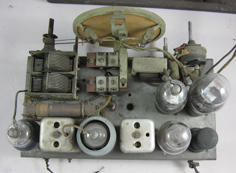
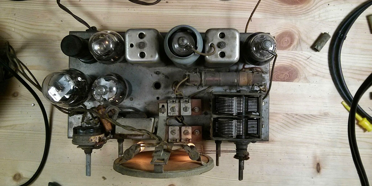
PHOTO 1. Top-down view of the DeWald 618 chassis.
Dead electrolytic capacitors in the power supply have killed many old radios, and the coupling and bypass capacitors can cause tubes to fail and coils to burn out.
Take a look at Photo 2.
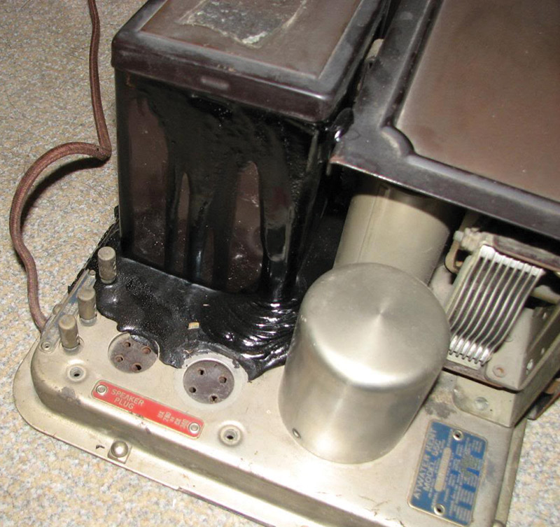
PHOTO 2. Bad electrolytic capacitors made this transformer burn out.
There are a few approaches you can take while going through component replacement. Some people argue it's best to replace only the electrolytic capacitors in the power supply, then one capacitor at a time powering up in between each. This takes quite a while, and with all the other components still original, is pretty risky. I'd personally never recommend such a practice for a radio from the early years, although with something manufactured in the late '50s and into the '60s, you might be able to get away with it.
It looks like someone already tried that approach on a radio a few years ago. Check out Photo 3. There are two modern electrolytic and one film capacitor, but the rest are 1930s-1940s replacements.
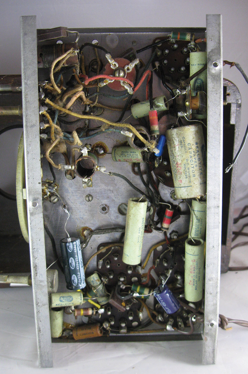
PHOTO 3. Underside of the chassis. Mostly '30s and early '40s capacitors, with some early 2000 era replacement parts thrown in.
I like to proceed carefully, one component at a time until all questionable capacitors have been replaced, then power it up and see what happens. By replacing each component one at a time and only lifting one lead at a time, it's easy to make sure you don't mis-wire anything.
Connecting a film capacitor to the wrong place in the circuit won't generally cause anything to burn out (since capacitors block DC current), but can cause the radio not to play, for example, by shunting the radio signal to ground before it gets to the next tube. Just be careful not to connect an electrolytic capacitor backwards.
Under the Chassis
Be careful working on a vintage radio! There are high voltages present. If you're working with a transformerless radio, make sure to use an isolation transformer as the metal parts might be in direct contact with your AC mains and could cause a serious injury. Use personal protection equipment and good ventilation while soldering. As always, go slowly and be careful!
Depending on your goal — a working radio or more of a historically accurate restoration — you can think about some extra steps to prep your new parts before you go through the full replacement. While it can be confidence-inspiring to see a whole set of shiny new film capacitors underneath the chassis, it looks a little out of place among the cloth wiring and hand-wound coils.
For a more period correct look, you can gut the old capacitors and re-stuff them with new replacements. It's the best of both worlds: A period look but the reliability of modern components!
Normally, if you're going to re-stuff the capacitors from your radio, you'd use the existing components which were installed when you found it. Later capacitors weren't good for re-stuffing as the sealing techniques improved and made them much harder to hollow out. This radio’s already had some work done, so there aren't enough original components to make a full set. Luckily, I have a handful of old capacitors I'd kept from previous projects and picked out a few which looked to be about the same color and had the right markings. My DeWald won't look like it's just off the assembly line, but it will still have the same time period look.
Re-stuffing the capacitors is a little time-consuming, but I think it's pretty fun. Grab your tools and supplies: a heat gun, a hot glue gun, clay, wax, the new capacitors, and your old ones to gut. Keep everything handy. You'll want at least one pair of pliers, too, for helping to extract the guts of the old caps. It's a good idea to do this step somewhere that's well ventilated as you'll make some fumes from the heat gun and the wax.
I like to use nitrile gloves while re-stuffing as there's a lot of unknown chemical residue in these old caps. (If you don't have gloves, wash your hands after this step before doing anything else!) Put down some newspaper so the molten wax doesn't go everywhere (Photo 4).
PHOTO 4. Capacitor re-stuffing station ready to go.
Turn the heat gun to moderately high, around 800 degrees F. Hold the capacitor you're re-stuffing by one lead and turn the heat gun on it. Keep rotating around slowly to heat the capacitor until the old wax starts to drip off, taking layers of grime with it and leaving behind mostly clean cardboard. Keep rotating the capacitor and heating with the heat gun until just the faintest whisps of bubbles or smoke starts to come from the ends. Then, secure the body of the capacitor and pull on one of the leads until it pops out.
Use a pen or other small object to push through the body of the capacitor and push the guts out the other side. That's it!
Now, you've got some nasty wax, a couple of loose wire leads, and a bundle of foil densely wound around insulating paper (Photo 5).
PHOTO 5. Empty capacitor tubes and removed guts.
Next, take the hollow cardboard tube and one of your new components. Axial lead film capacitors work best here, but you can bend the leads of a radial component, and that's just fine. Slide the new cap into the tube, center it, and use a small dab from the heat gun to hold the part in position inside. Let the glue harden for a few seconds, then take your brown or beige polymer clay and push it into the sides, filling up the empty space and forming the end plugs of the capacitor.
Once you've filled in the ends, take the newly re-stuffed capacitor and give it a quick dip once or twice in your molten bee's wax (Photo 6). Let it dry for a few seconds and set aside.
PHOTO 6. Dipping a re-stuffed capacitor in new wax to seal it.
You've re-stuffed a capacitor! Repeat for the rest of the caps in your radio, and you'll have a new set (Photo 7).
PHOTO 7. The assorted capacitors for this DeWald radio.
Re-stuffing the electrolytic capacitors is a little harder. Electrolytic capacitors are commonly found in cans above the chassis due to their size back in the day. Some people remove these cans, drill the case open just above where it mounts, extract the guts, and bundle up new electrolytic capacitors inside an insulator before gluing and taping the assembly back together. It's messy and frankly, in my opinion, it's tough to make it look good. Dealing with those hassles isn't an issue for the DeWald, though. It's missing its can capacitor, and there's a set of modern electrolytics instead.
Here, I'm going to fake it a little bit. The radio only needs to really look period correct at first glance, and modern electrolytics are so much smaller than they used to be. I found a slightly larger shell of an old paper capacitor which will fit a pair of 22 µf 450V electrolytic capacitors inside its diameter (back to back), with just a tiny bit of room to spare.
For this one, I gutted the old capacitor, then slid both electrolytics in. Now, there's a paper capacitor with two leads coming out of each end. It's not quite historically accurate, but it looks good at first glance (Photo 8).
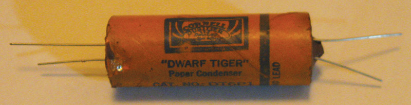
PHOTO 8. Both electrolytic capacitors stuffed into one tube.
Down to Business
Armed with a new set of “vintage” capacitors, it's time to swap out the components. Just cut and replace! Try and get the new capacitors as physically close to the position of the old capacitors as possible. Lead dress — the arrangement of the components and wires — is a big deal in radios this old, and component positions which differ radically from when it was built can cause problems like interference, feedback, and squealing when it's powered up (Photo 9).
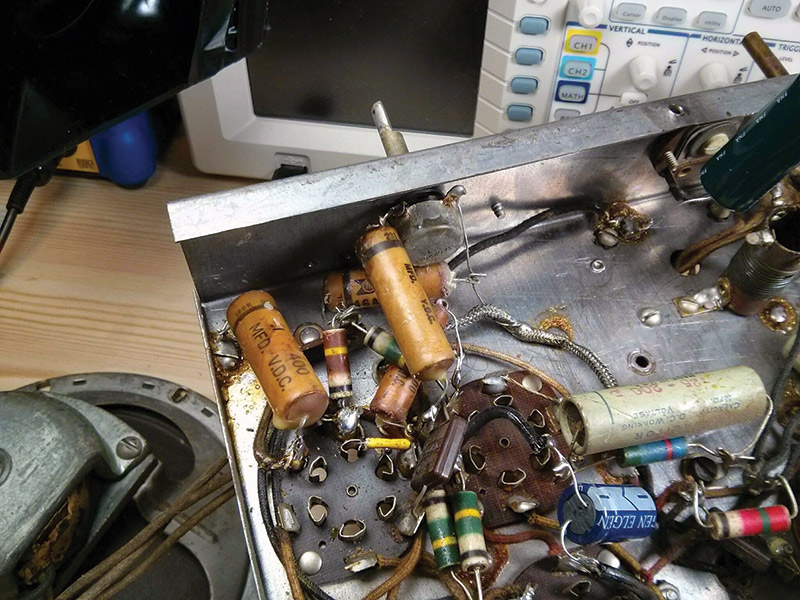
PHOTO 9. Starting to replace the old caps.
Sometimes radios like this are built in layers, and you have to remove some top components to get to the ones below them. I use an alligator clip jumper wire on each end of the component I've temporarily bent out of the way to make sure I don't lose my place while working on the deeper layers. Then, I come back and replace the jumper placeholder. I did end up extending some leads for the new "electrolytic" capacitors I installed, using leftover cloth covered wiring from another project to preserve the appearance (Photo 10).
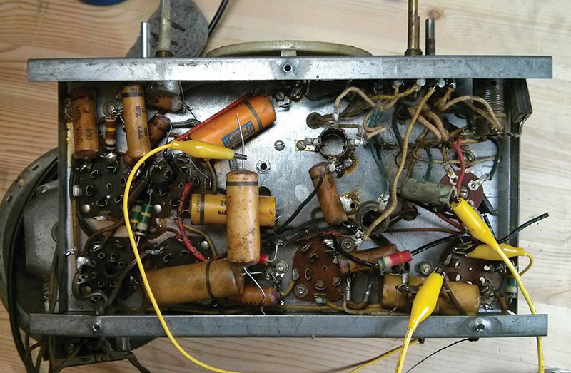
PHOTO 10. Further along, with jumpers to keep track of parts I've removed to get to the ones below.
While in there, I spot-checked the resistors in the radio. Resistors were made of a molded carbon compound back then, and as they age and absorb moisture from the atmosphere, they're known to change in value. This doesn't usually keep the radio from working, but it won't be performing at its best with wrong-value resistors. The color codes have the same meaning as they do today, but they're read a little differently: body-tip-dot.
The "body" of the resistor — the largest color section — is the first digit. The "tip" or color band at one edge of the component is the second digit, and the "dot" — or color band — in the center of the body color is the multiplier. Shown in Photo 11, this 100K ohm resistor (brown-black-yellow) is within 20% of its marked value, so doesn't need any further action.
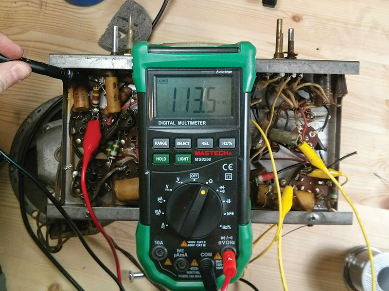
PHOTO 11. Measuring the drift on a nominal 100K ohm resistor.
I checked a handful of others and they were in spec, so in this case, none needed to be replaced. That's actually pretty rare. I've run into resistors which had drifted to over 100% of their marked value.
You can still get new manufactured carbon composition resistors, although they're a bit more expensive than other types. Visually, they're a different style, looking similar to modern resistors, but those did start turning up in the late '30s. You'd have to replace every one if you wanted a uniform look. It's possible, just a ton of work.
There's not a whole lot more to say about this step. It took about an hour and a half to swap out the components, and now it's ready for the first power-up (Photo 12)!
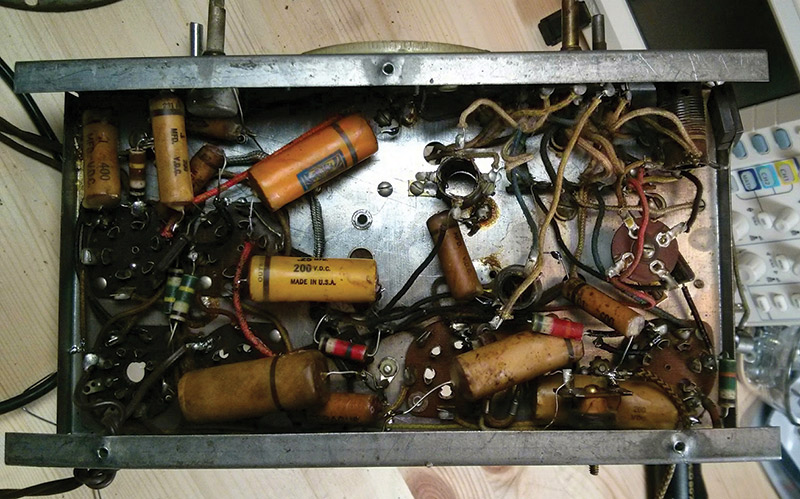
PHOTO 12. Component replacement complete. Looks good!
Fingers Crossed
I've double-checked my work to make sure no leads are touching which could cause a short, and reinstalled the tubes and ballast. Now, for the obligatory safety warnings: If you're working with a radio that uses a power transformer, it's fine to connect directly to the mains at this point. For a transformerless radio like the DeWald, however, you absolutely must use an isolation transformer or you risk a deadly electric shock.
The radio's metal parts could become energized at your mains voltage and any contact with an earth ground — like a concrete floor, a cold water pipe, or a piece of grounded test equipment — could cause a short through your body or your gear. Bad news! Don't chance it! Use an isolation transformer and stay safe (Photo 13).
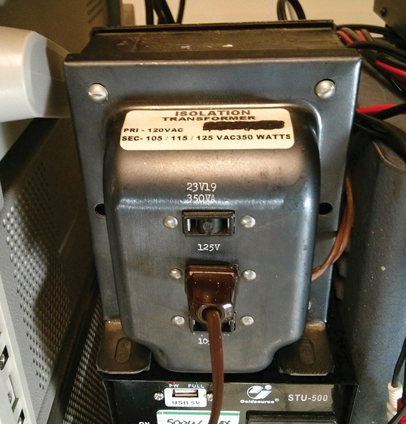
PHOTO 13. Isolation transformer for safety.
After making sure you're safe, flip the switch and hold your breath! This is the part where you'll see smoke if there's a problem (Photo 14).
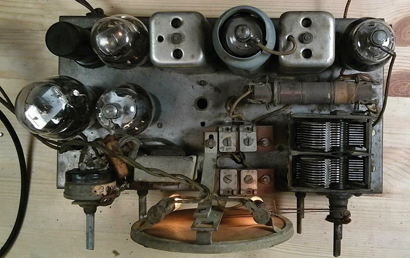
PHOTO 14. First power-up with the lights on.
On most radios, the switch is on the volume control, so just click it on but don't turn the volume up yet. Otherwise, turn the volume all the way down and flip the power switch separately.
Do the glass tubes start to glow a little inside as their heaters fire up? On a transformerless "series string" radio, if any tube has an open filament or heater, they'll all fail to light and the radio won't get any power at all. So, if you have no power, double-check that the tube filaments aren't open.
Listen for sparking and arcing. If you hear any, power the radio off right away and look underneath to see where it's shorting out and correct that problem.
Do you see or smell any smoke? Likewise, power-off immediately and look to see what went wrong. If it's not obvious, you might need more in-depth diagnostics with help from a place like the Antique Radio Forum (www.antiqueradios.org) or the Audio Repair community on Reddit (www.reddit.com/r/audiorepair) if this is your first project.
If all you get is a loud 60 or 120 Hz hum that doesn't vary with the volume control, stop. You have an issue with the power supply and need to double-check your filter capacitors. Most of the time the negative terminal of both capacitors will connect to circuit common, but occasionally you'll find a negative-filtered power supply where both positives connect together, but the negative ends connect to different circuit potentials.
One common pitfall is failing to notice that, say, one of two cans on top of the radio chassis is actually insulated and connects to a different negative than the other. Check your connections against the schematic and ask for help if you're still having trouble. Don't run the radio in this condition as you'll likely cause a filter capacitor to explode like a firecracker or damage your transformer.
I flipped the switch and listened, but got absolutely nothing from the speaker. After poking around at various connections and test points, I found the problem pretty quickly: A lead going to the field coil on the back of the speaker had broken! That would pretty much take the power supply out of the circuit.
Fortunately, this was an easy fix, and I was back up and running (Photo 15). The next power-up after reconnecting the broken wire started pulling in AM stations on the first try (just like it should) with a very short test lead antenna.
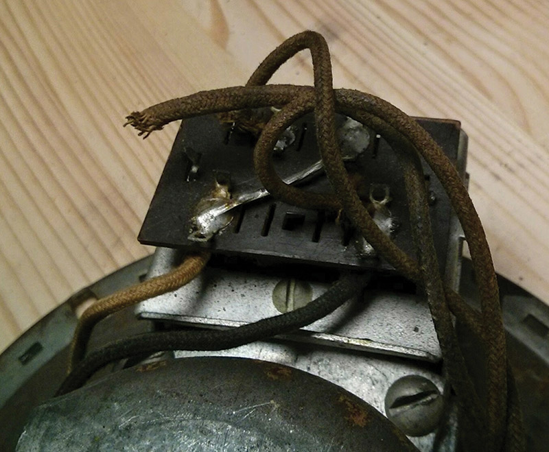
PHOTO 15. Broken field coil lead.
If you're still having trouble getting the radio to make sounds after the component replacement, you'll need to do some more in-depth diagnostics. Double-check that everything is plugged in correctly. If your radio has top caps on the tubes, make sure they're connected. You can carefully tap each of the top caps with the metal end of a screwdriver and listen for a click in the speakers. If you don't hear any clicks, it means there's a problem keeping the signal from passing through the radio properly.
Clicks but still no reception might mean there's a problem with the radio's oscillator or front end keeping the radio signal from being received correctly. Ask for help on a forum if it doesn't seem to be going anywhere.
The DeWald is now pulling in stations, but not quite at the right spot on the dial. It's time to fix that!
Aligning the Radio
Alignment is the process of adjusting the radio's tuned circuits so stations come in loud, clear, and ideally at or near the correct numbers on the dial. While these radios would certainly have peaked up perfectly when they were brand new, age-related changes in the coils and adjustments can make this part a little more difficult. Sometimes the best you can do is "close" but not "perfect." Don't worry too much about it.
If your radio has a set of alignment instructions, go ahead and follow those. There are usually two parts to the alignment: IF alignment, where you adjust the transformers to get signal through the radio as efficiently as possible; and RF alignment, where you adjust the dial tracking and positioning. You can generally adjust both with simple tools like your multimeter and a small screwdriver — or even just your ears!
In the Rider's Perpetual Troubleshooter manual for 1937 — a great resource for radio repairs — DeWald provided alignment instructions:
"IF Alignment: Intermediate frequency peaked at 456 KC. Connect test oscillator to grid of 6A7 and chassis. Short circuit stator of front section of variable condenser during this operation. Then, peak IF trimmers for maximum signal."
That's a little bit complicated with the old terminology, but not too bad. To follow those instructions to the letter, you'd set the signal generator to put out a modulated 456 kHz output through a series capacitor to the grid of the 6A7 tube, and connect a jumper across the front tuning capacitor section to short out the incoming signal and ensure you're only getting the test generator's input (Photo 16).
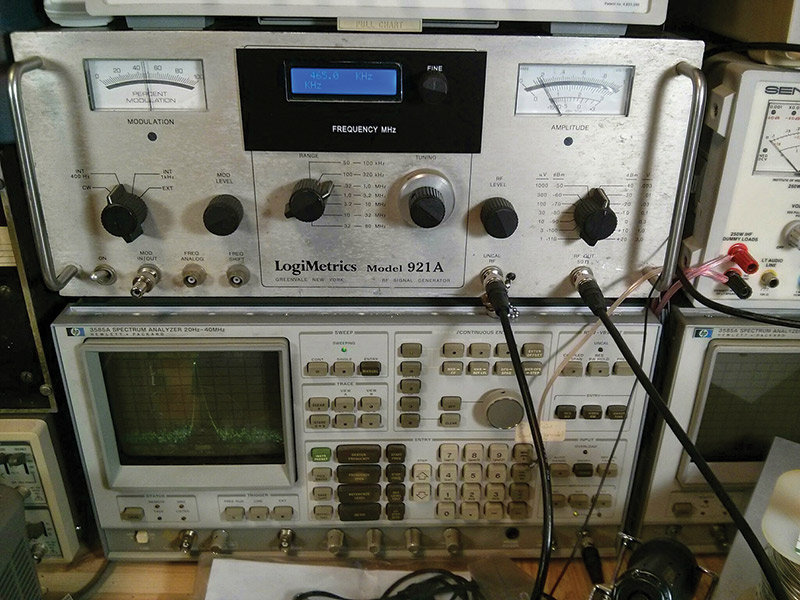
PHOTO 16. My signal generator — the LogiMetrics 921A — hooked up to an HP 3585A spectrum analyzer for monitoring.
Then — with your multimeter hooked up across the speaker's voice coil — adjust the trimmers on the top of the IF transformers for the highest observed voltage. Start out with the last IF transformer closest to the radio's detector, and work your way back to the front towards the 6A7, in this case.
You should use a plastic tool to align your radio's IF transformers. Since the high B+ voltage passes through one side of the transformer, one trimmer in each transformer will be at that high voltage. If you touch the grounded metal side of the can, you'll cause a short. If you don't have a plastic tipped screwdriver, make sure to use at least one with an insulated handle and wrap the shaft with electrical tape to make sure it won't short out. Don't use an all-metal screwdriver or you'll get a shock.
If you don't have a modulated signal generator, you can still do this step by ear. Tune into a loud station, set the volume about mid-way, and listen to the program as you adjust the trimmer for maximum volume and the highest reading on your multimeter. It's that easy!
You'll probably be able to get a tiny bit better results using the full test set, but realistically, you're unlikely to notice a large difference if you just align the IF chain "by ear" versus with a signal generator.
Next up is the RF alignment. DeWald says:
"Remove short from stator of variable condenser. Turn wave band switch to Broadcast. Connect test oscillator to antenna and chassis. Set test oscillator and radio dial to 1500 KC and peak var. Cond. Trimmers for maximum signal. Set test oscillator [and radio dial] at 600 KC and adjust padder condenser in front of chassis for max signal. During this operation the variable condenser must be rocked. Readjust 1500 KC."
Pretty straightforward. Adjust the high end trimmer to bring the 1500 KC test signal to the correct position on the radio's dial, then adjust the trimmer next to it (which tunes the antenna) for maximum output. Then, move the dial, reset the signal generator, and adjust the second trimmer on the front of the radio for the same. Go back and re-adjust the high end again. This should make the radio's dial track evenly across the whole AM broadcast band.
Don't stress if you can't get it perfect, but it should be much improved (Photos 17 and 18).
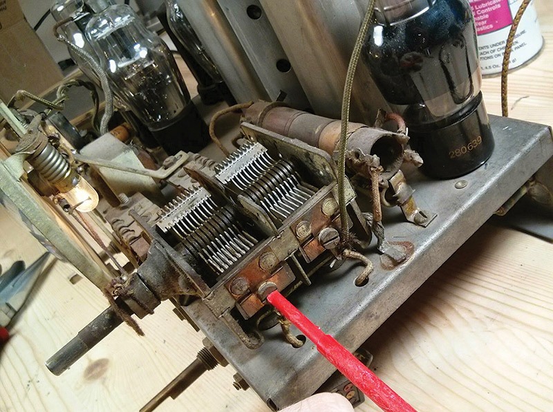
PHOTO 17. Adjusting the trimmers on the side of the variable capacitor.
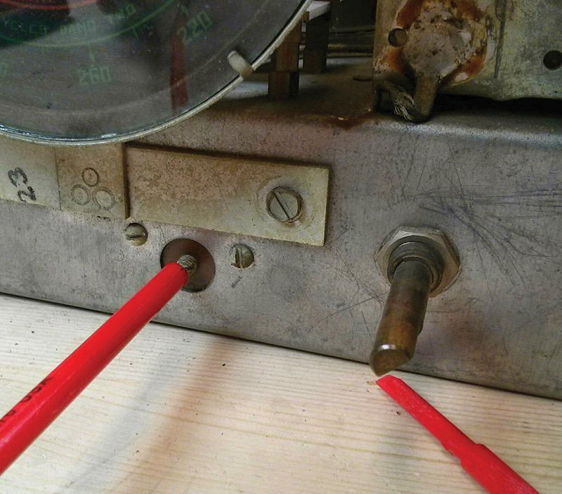
PHOTO 18. Adjusting the padder trimmer on the front of the radio.
If you don't have a signal generator, it's still no problem! You'll need to do a little more work, though. Skip the step about shorting out the variable capacitor, find a local AM broadcast station around 600 and 1500 kHz, and tune those stations instead of a test signal. It won't come out perfect, but it will get you pretty close.
At this point, all that's left to do is to enjoy your handiwork for a few minutes, then box it all back up into the case. We've replaced all the components, powered it up, discovered and fixed a broken wire, and aligned the radio for the best possible reception.
Putting it All Back Together
Put everything back in the cabinet, secure the speaker to its mounting bolts, re-attach any knobs and covers you removed, and reinstall the chassis screws that hold the radio's guts in place. Do one final power-up and tune around to make sure you didn't bump anything in the process. Now, you're all done!
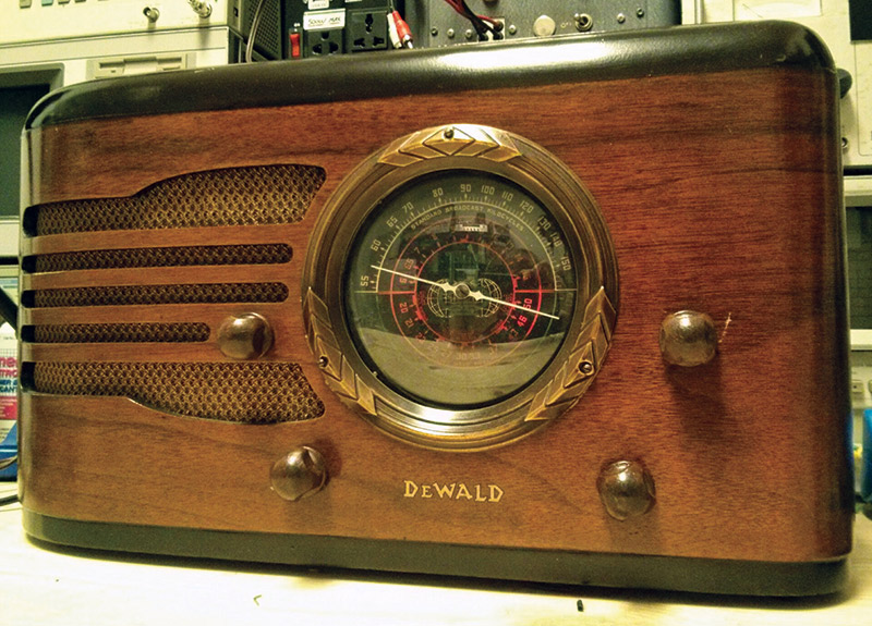
PHOTO 19. Back in the case and ready for action!
Give the radio a home on your shelf and make sure to turn it on and enjoy it on a regular basis. You've successfully brought a piece of electronics history back to life, and with any luck, you've had fun doing it!
What's Next?
These two articles covered a very easy repair, where everything pretty much went right the first time. In my own personal experience, about three-quarters of the radios I've encountered didn't need any special troubleshooting and started receiving stations the first time they came back online. That's certainly not guaranteed, though.
I'll cover some troubleshooting techniques and some advanced alignment techniques in future articles. Until then, check out the Antique Radio forum or Audio Repair on Reddit for in-depth assistance. There's thousands of friendly active members who love to help — many with experience from when these radios were brand new in the first place.
Until next time, enjoy your radio! NV