Not long ago, I put together a project, housed in a plastic RadioShack box, which contained a component that could get hot enough to self-destruct in a closed box. I added a small cooling fan to the box, but the noise was excessive.
I decided that I could minimize the noise if I only ran the fan at the speed necessary to cool the components.
I considered just slowing the fan to some speed that produced less noise. The problem with just running the fan slower is that the cooling may be inadequate. A rise in ambient temperature or higher power dissipation in the circuit would cause everything to overheat. So, I decided to adjust the fan speed with temperature, running at minimum speed when the circuit is cool and increasing fan speed as the temperature increased. I measured the temperature of the hot component with a thermistor and adjusted the fan speed based on that temperature.
A schematic of the circuit is shown in Figure 1.
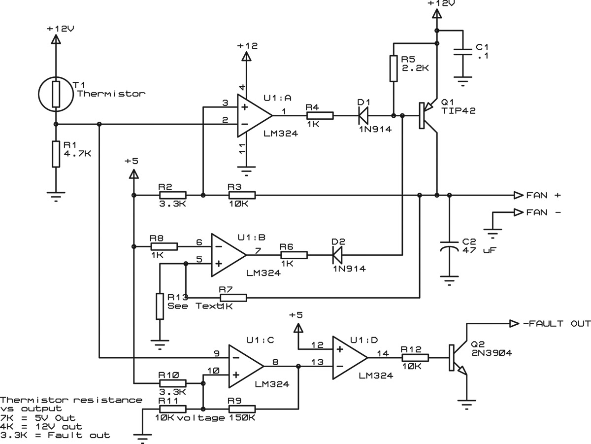
FIGURE 1. Schematic of the fan controller circuit. T1 is a thermistor mounted to the component needing to be cooled.
The circuit uses a single quad op-amp, U1, an LM324. Q1 is a PNP power transistor that supplies current to the motor. T1 is a thermistor that provides temperature sensing, and is mounted to the component that needs to be cooled.
T1 is an NTC (negative temperature coefficient) thermistor, which means that the resistance goes down as temperature goes up. The resistance of T1 is about 10K at room temperature, falling to about 2.8K at 70°C. Since most commercial electronics operate to about that temperature, the fan needs to keep the temperature below that point.
Small DC fans are typically one of the less reliable components in an electronic system, so the circuit includes a fault output to indicate when the temperature rises beyond acceptable limits (in this case, a bit less than 70°C). This could happen if the fan fails or if the ventilation holes become plugged with dust or covered with a piece of paper. The fault output can notify a processor to shut off power or take some action to reduce power dissipation in the circuit.
Q1 operates in linear mode, supplying current to the motor. With a larger, higher current fan, this arrangement could potentially cause significant heating from Q1 itself. The fan used here draws less than 100 mA at full supply voltage, so that is not an issue. Note that the feedback network (R2/R3) connects to the non-inverting input of U1A (pin 3). Ordinarily, feedback to an op-amp goes to the inverting input (pin 2, in this case), but in this circuit, Q1 provides an additional stage of inversion. This effectively swaps the functions of the inverting and noninverting input pins.
Q1 is turned on by current flowing to ground through the base. Note that there is no direct relationship between the voltage at the base of Q1 and the output voltage. Q1, being a bipolar transistor, is a current amplifier, so U1A will sink sufficient current through the base to produce the appropriate voltage at the output.
The fan I used will operate from 5V to 12V. At 5V, the noise is almost inaudible, so the circuit always supplies 5V to the fan, through U1B. As the temperature rises so that the output needs to rise above 5V, U1A begins to sink current, raising the fan supply voltage. Operating the fan in this way provides two advantages: First, there is always some airflow through the box. Second, it simplifies the circuit since there is no need to add circuitry to turn off the output when it would be below the minimum fan operating voltage.
U1C provides fault detection. When the temperature rises above approximately 65°C, U1-8 goes low. U1D is just an inverter to drive Q2, providing an open-collector output. This allows multiple fan circuits to share a common fault signal. U1C includes a small amount of hysterisis through R9 to insure that the fault output is a well-defined transition.
Note: R13 is not installed for a fan that can operate at 5V. For a fan with a minimum operating voltage higher than 5V, R13 is needed to provide that voltage to the fan. See the sidebar Working the Equations for details.
Calculating Circuit Values
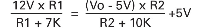
In an op-amp that is linear (the output is not saturated at either supply rail), the inputs (U1-3 and U1-2, in this case) will be at the same voltage. The voltage at U1-2 is controlled by the voltage divider comprised of T1 and R1 and varies with temperature. The voltage at U1-2 is controlled by the voltage divider comprised of R3 and R2, and varies with fan voltage.
The equation for U1-2 can be written as:

The equation for U1-3 can be written as:

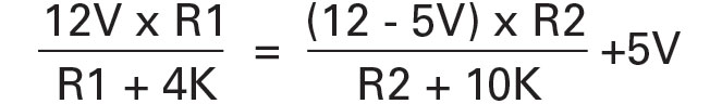
I defined two endpoints for the circuit, with the fan operating at 5V up to about 40°C, where the thermistor resistance is about 7K, and applying the full 12V at about 60°C (thermistor resistance about 4K). By setting R3 to 10K and then setting pin 3 equal to pin 2, we have the following equations:
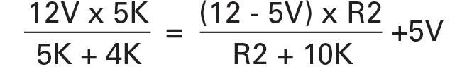
5V output:
Since Vo is 5V, the right side of the equation reduces to 5V and R1 is 5K.
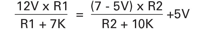
At the other end of the range, the equations are:
which makes R2 equal to 3.12K. Since I didn’t need precise temperature control, I used the nearest 5% resistors; a more precise circuit would use 1% or better parts. Note that R1 reduces to a simple equation only because the reference for pin 3 is equal to the minimum fan voltage. A different reference value (such as a precision 2.5V reference) would result in solving both equations simultaneously (remember high school algebra!) for the values of R1 and R2. Also, many 12V fans will not operate as low as 5V, and a different minimum fan voltage would also change the result.
For more precise control, you would use the following 1% values:

In this circuit, the 5V and 12V supply voltages are used as references, so the temperature control will vary with supply voltage. More precise control would require more precise voltage references.
U1B sets the minimum fan voltage at 5V. If you use a fan with a higher minimum voltage, you would need to apply that voltage to pin 6 through a voltage divider. For example, a fan that needs at least 7V to operate would make the equations look like this:
7V:
12V:
If you solve these (see “Working the Equations”), you get R1 = 6.25K and R2 = 4.95K. These values would produce 7V to the fan at 40°C, and 12V to the fan at 60°C. In some cases, when you solve equations like this, you get a negative resistance value. In those cases, you have to change a resistor or reference voltage in the circuit to get the result you want. The exception is if you get a quadratic equation (like you will if you work through this example) with one positive and one negative root. Then the positive root is the resistance you want.
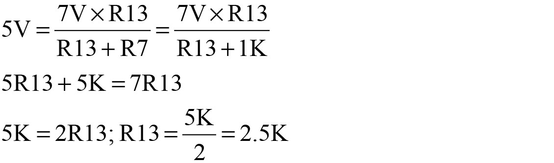
To complete the 7V conversion, U1B would be set to produce a 7V output by making R13 equal to 2.5K.
Most thermistors have very low mass, so if you change component values, you want to be careful with R1. If the value of R1 is too small, the thermistor will dissipate enough power to heat itself and affect the sensed temperature. The maximum power dissipated by the thermistor in this circuit is about eight milliwatts.
Thermistor Attachment
The thermistor can be used to measure air temperature inside the enclosure, but you typically want to measure the temperature of an IC, heatsink, or other component. In this case, I used a small bead-type thermistor, glued into the barrel of a ring terminal (Figure 2).
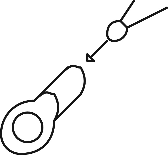
FIGURE 2. The thermistor for this project was a bead-type thermistor glued into the barrel of a ring terminal. Conductive epoxy is the best way to do this. You can also get thermistors already attached to tabs, drilled for mounting.
The ring terminal was then attached to the hot component with a machine screw and nut. This would work with a component such as a hard drive, or a part with a heatsink. If the part is, say, a TO-220 transistor, you could attach the thermistor with the same screw that attaches the transistor to its heatsink.
If you are measuring the temperature of an IC, you would want to glue the thermistor to the IC package or to a heatsink that is then glued to the package. Thermally conductive epoxies for mounting thermistors are available from companies such as Omega. Various manufacturers, including RTI Electronics and Vishay make thermistors already mounted to metal tabs with mounting holes.
Testing
Testing is fairly simple: Connect +12V and +5V, and (optionally) connect a fan. The output voltage should be about 5V. Use a heat gun or hair dryer to heat the thermistor; the fan speed and voltage should increase as the temperature goes up. To test the fault output, connect a 10K pullup from the fault output to +5V; the fault output should go low around 70°C.
Temperature Control
The control circuit does not attempt to maintain a constant temperature. Instead, the temperature is allowed to float. For a given ambient temperature and circuit power dissipation, the temperature will tend to stabilize at some value. However, given the significant thermal mass in this enclosure (and associated delay between changing fan speed and resulting temperature change), maintaining a constant temperature would be difficult, anyway.
Although maintaining a fixed temperature would seem more “normal” for a control system, in this case, it would result in higher fan noise. At higher ambient temperatures, or under increased load, a constant-temperature circuit would run the fan faster to maintain the temperature. By allowing the temperature to float up with ambient temperature and circuit power dissipation, the average fan speed will be lower (although the temperature will usually be higher than a fixed setpoint would be).
So, what happens if the fan runs at full speed all the time and the temperature is still above the upper limit? That means the fan is too small to start with, or that the ventilation is either inadequate or blocked. In that case, it doesn’t matter if the circuit is a constant-temperature controller or not — no type of fan control can provide adequate cooling.
The resistance of an NTC thermistor does not have a straight-line relationship with temperature; instead the curve is approximately logarithmic (Figure 3).
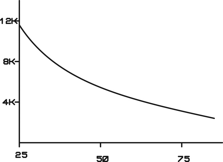
FIGURE 3. The thermistor has an approximately logarithmic temperature-resistance curve. This means that the fan speed will increase faster near lower temperatures, and increase more slowly as the temperature approaches maximum.
Since the fan supply voltage varies with thermistor resistance, the fan supply voltage will increase faster around 5V, and slower as it approaches 12V.
Other Types of Fans
Another approach to this project would be to control fan speed directly (instead of controlling fan voltage) using a fan with a tach output. These fans produce a pulse once or more per revolution. Of course, this approach requires some method of translating the tach signal to a control voltage — typically with a microcontroller or fan controller IC.
PWM (pulse width modulation) could also be used to control the fan, and would eliminate any problems with power dissipation in Q1. However, this requires a fan that is capable of PWM operation — many low-voltage DC fans use brushless DC motors with internal controller ICs that don’t respond well to PWM control.
Minimum Current
Although the fan used here is a low-current device, if you were operating from batteries, you might want to turn the fan completely off if the temperature is low enough. The simplest way to do this is to add a microcontroller (covered next). You could also add circuitry to inhibit the fan output completely below 5V.
Adding a Microcontroller
By now, some readers are asking why not just use a microcontroller for this circuit? There are a number of controllers with on-chip ADCs to read the thermistor, and adjusting the temperature setpoints is a simple matter of changing the firmware.
A microcontroller-based design would work, but many of the parts in this circuit would still be needed: the thermistor voltage divider, the output transistor, and an op-amp to drive it. In addition, the microcontroller would require a DAC unless one was available on-chip. A microcontroller solution would potentially increase EMI (not a consideration in my one-of-a-kind project, but certainly a consideration on a production design).
A microcontroller is suitable for this design if any of the following are true:
- A microcontroller is already used elsewhere, so added cost is minimal.
- PWM motor control is needed.
- The temperature-fan speed curve needs to be “linearized” to compensate for the logarithmic thermistor curve.
- Setpoint adjustment needs to be customized to the application, or environment.
- Constant temperature control is needed.
- You want to turn the fan completely off below a particular temperature for lower current drain (as in a battery application).
Better Precision
The largest sources of error in the circuit are:
- 5% resistors
- 12V reference for thermistor circuit
- Thermistor tolerance
As already mentioned, the circuit uses 5% resistors, but 1% values would produce better accuracy. The 12V and 5V references could be replaced with precision 2.5V or 5V references. However, doing so means that the equations must be reworked with the thermistor you plan to use. It is possible to pick values that cannot be “mapped” to the output voltages you want. This will be obvious when you do the math (see “Working the Equations”) because you will end up with a negative value for one or more resistors.
Finally, the thermistor tolerance affects precision. Thermistors typically have a 5% tolerance, but 1% or better parts are available. You could also characterize the thermistor you plan to use, but if you need that level of precision, you probably need to do some sophisticated airflow analysis.
Conclusion
This basic circuit allows you to control the speed of a fan to suit your noise tolerance. Using the example equations, you can change the temperature ranges and thermistor to adapt it to your needs and specific circumstances, and keep your components cool! NV
Working the Equations
The fan used in this circuit will operate from 5V to 12V. Some 12V fans will not operate down to 5V; they may only operate from 7V to 12V. For those who want to follow the math, here is how the op-amp equations are solved for 7V to 12V operation:
For 7V:
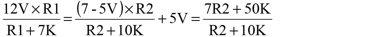
Expand and then collect terms:
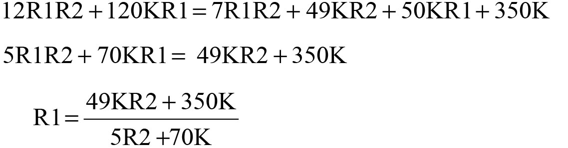
For 12V:
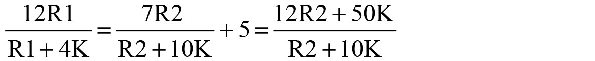
Expand and collect terms:
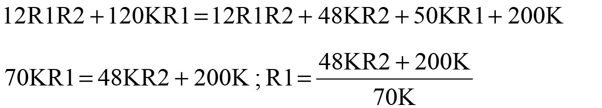
Substitute second value for R1 into first equation:

Expand and consolidate:
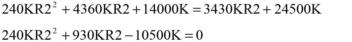
Solving this with the quadratic equation results in R2 = 4.95K (the other root is negative). Inserting that back into either equation for R1 yields R1 = 6.25K.
Substituting a different thermistor or different temperatures just means you have to substitute the resistance values for the thermistor/temperature you want to use. For example, if your thermistor has a resistance of 8K at the lowest fan temperature, you would substitute 8K for 7K in the equation for 5V operation (or 7V operation, in the above example).
Calculation of R13:
The original circuit did not use R13 because the fan operates at 5V. However, for a fan requiring a minimum of 7V, U1B needs to produce a 7V output instead of a 5V output. Since the reference to U1B (pin 6) is 5V, we need U1-5 to be at 5V when the fan voltage is at 7V:
The same thing could be accomplished by leaving out R13 and connecting a voltage divider from 12V to ground, using values that produce 7V at the junction of the two resistors. U1-6 would connect to the 7V junction point.
The thermistor used in this project was a surplus unit from an unknown manufacturer. A commercial part would have different resistance/temperature values. For example, the Vishay 2381 645 90169/NTCALUGE2C90169 is cemented to a mounting lug and has a resistance of 5.3K at 40°C and 2.49K at 60°C. The corresponding circuit values would be:
R1: 3.9K
R2: 3.9K
R3: 7.5K
R10: 4.5K