I do a fair amount of printed circuit board design with ground planes and power planes. Often, they require vias to provide power or grounds to components. This is especially true if using four-layer boards. If you recall, I recently designed a four-wire Kelvin low resistance ohmmeter with a digital readout for measuring low resistances. This got me thinking that it would be nice to have a probe that would be a go/no-go device just for traces. It ended up being considerably cheaper than the digital readout.
To save board space, the first board I designed was 1/2” wide x 3.8” in length. I used two solderable three volt CR2450 620 mAh batteries. It turned out to be a disaster as the batteries were unstable when mounted, difficult to solder, and could short each other.
I then discovered that Renata made a perfect battery holder for the CR2450 battery. I redesigned the board widening it to 1” x 3.8” in length.
THE CIRCUIT
Refer to the schematic and my previous article on the Kelvin ohmmeter for the following discussion.
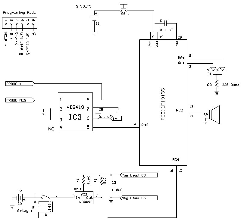
Schematic.
For the four-wire Kelvin ohmmeter, you need to use two batteries: one for the voltmeter and another for the constant current source. The probe uses two three volt coin batteries mounted in their respective holders.
To ensure that the voltmeter and constant current source batteries are separate, I used a relay to turn on and off the constant current source.
For the constant current source, I used an Analog Devices, Inc., LT3092 which can go down to 1.2 volts input and up to 200 mA.
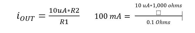
So as not to stress the battery supply, I did the following: Set the current source to 100 mA and turn it on for a very brief time while the analog-to-digital converter (ADC) measures the voltage. The current source is set by two resistors, R1 and R2 and the calculation is the following:
The voltage measuring unit uses a Microchip PIC16F19155 microprocessor. It has a 12-bit ADC and adjustable voltage references of 4.096, 2.048, and 1.024. Prior to the ADC is an Analog Devices AD8418WBRZ current source operational amplifier. This is a differential amplifier thus eliminating stray common voltages from traces and measuring probes. It also amplifies the differential voltage by 20, thus increasing the unit’s sensitivity.
Since this a four-wire ohmmeter, you may wonder where the fourth wire is. It’s a trace from the constant current source connected directly to the + probe. The two negative wires are connected at the negative probe.
I paralleled two ports of the micro to each input of the buzzer and relay to increase the mA output.
A bicolored LED provides an indicator of approximately the resistance measured. Red = above one ohm. Orange = between 0.01 ohms and one ohm, and green = below 0.01 ohms. I added a buzzer as an indicator for below 0.01 ohms.
The following sequence is used to measure the ohms:
- Power the unit with the switch.
- Turn on the current source for 1 ms (relay response time).
- Measure the voltage using the micro’s ADC and a 2.048 voltage reference.
- Use the built-in algorithms to determine which LED should light.
- Repeat.
CONSTRUCTION
This is a two-sided board with surface-mount components. A complete kit is available from the Nuts & Volts Webstore. The schematic and board files were drawn using ExpressPCB free software available from www.ExpressPCB.com. The board files and the programming code are available in this article’s downloads.
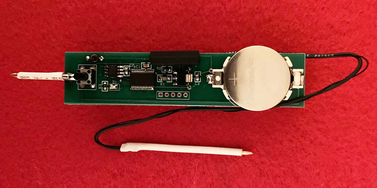
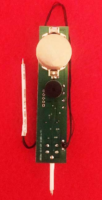
Top of board.
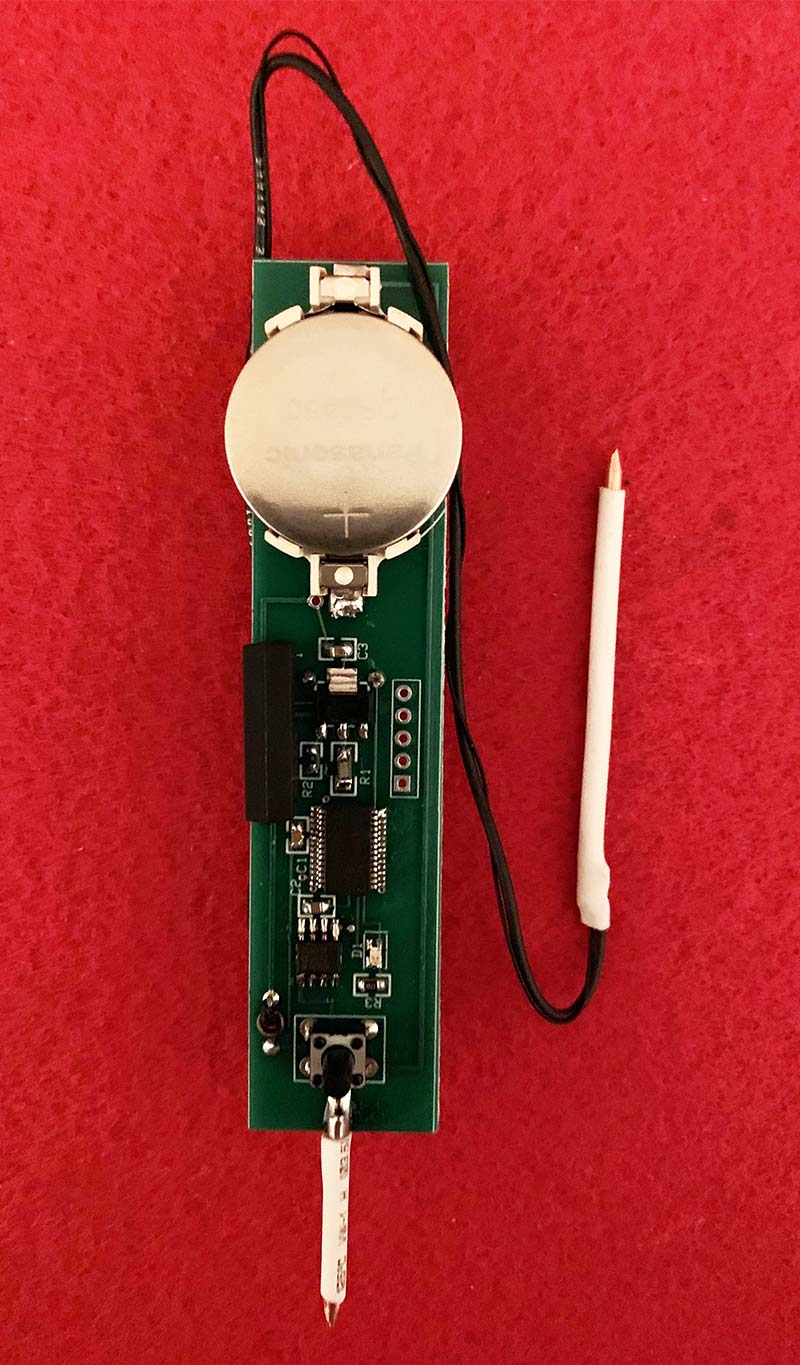
Back of board.
Solder C1, C2, C3, R1, R2, and R3. Solder IC1, IC2, and IC3 noting that pin 1 is either a dimple or a dot on the component. Solder the LED noting the green mark is the negative terminal. Solder SW1.
Turn the board over and solder in the buzzer noting the long pin is the positive terminal. Solder the relay noting the notch as pin 1. Solder the two battery holders noting the positive terminal.
Pass the 10” #24 wire from the bottom of the board through the strain hole and solder to the S- pad. Perform the same task and solder the wirewrap wire to the P- pad. Loosely wrap the smaller wire around the # 24 wire.
I ran into problems with the probe at first. I thought it would be a good idea to use corsage or bonnier steel pins. However, their resistance is above 0.01 ohms.
Next, take the 3.5” piece of #12 copper wire and point both ends using a file or sandpaper. Cut the 3” piece into two probes at 1” and 2”. Solder the 1” piece to the S+ and P+ pad. Solder the 2.5” to the two wires. Add shrink tubing if you like.
USING THE PROBE
Add two CR2450 batteries to the holders. Press the switch and red LED should light. Short the wire lead to the board probe and press the switch. The green LED should light and the buzzer should buzz. If you have a 0.1 ohm resistor, place it between the probes, press the switch, and the orange LED should light.
I hope you’ll find this probe a handy and welcome addition to the Kelvin ohmmeter. NV
Parts List
| PART |
DESCRIPTION |
QTY |
VENDOR# |
VENDOR |
| B1-B2 |
CR2450 |
2 |
CR2450 |
MOUSER |
| Battery Holder |
CR2450 holder |
2 |
614-SMTU2450N-LF |
MOUSER |
| Buzzer |
Three volt |
1 |
665-AI1223TWT3V2R |
MOUSER |
| C1-C2 |
0.1 µF 805 |
2 |
963-LMF212B7104KGHT |
MOUSER |
| C3 |
1.0 µF 805 |
1 |
963-UMF212B7105KGHT |
MOUSER |
| D1 |
LED Bi-colored |
1 |
604-APHBM2012ETSGTC |
MOUSER |
| IC1 |
PIC16F19155 |
1 |
579-PIC16F19155-I/SS |
MOUSER |
| IC2 |
Current source |
1 |
LT3092EST#PBF |
MOUSER |
| IC3 |
Op-amp |
1 |
AD8418WBRZ |
MOUSER |
| R1 |
0.1 ohm 1206 |
1 |
KDV12FR100ET |
MOUSER |
| R2 |
1K 805 |
1 |
AC0805FR-7W1KL |
MOUSER |
| R3 |
220 ohm 805 |
1 |
RC0805FR-07220RL |
MOUSER |
| Relay |
Five volt Reed |
1 |
934-HE3621A0500 |
MOUSER |
| SW1 |
NO Push 8 mm |
1 |
TL1105CF100Q |
MOUSER |
| Wire 1 |
10” #24 |
1 |
734411 |
JAMECO |
| Wire 2 |
10” Wirewrap |
1 |
22577 |
JAMECO |
| Probe |
3” #12 |
1 |
Strip |
LOCAL HARDWARE |
Downloads
What’s In The Zip?
Asm File
Probe Circuit Board Pattern*
Schematic
Parts List
* The .rrb file is the new extension from “Express PCB Plus.” For their new software go to https://www.expresspcb.com/ for their free download. There are no Gerber files.