Let's take a look at some specific electrical properties of both light bulbs and LEDs, and use them to discuss junctions in DC circuits. I'll start by posing a question. Look at the circuits in Figures 1 and 2. In Figure 1, two light bulbs (with different power ratings) are wired in parallel across a battery. In Figure 2, two LEDs (of different colors) are wired similarly. The question is, if these circuits are turned on, what would happen?
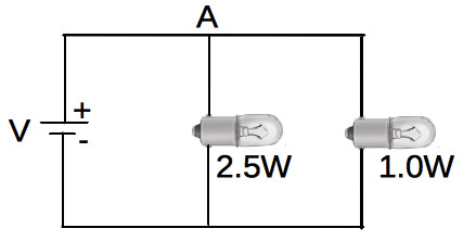
FIGURE 1. Two light bulbs with different power ratings, driven in parallel by a power supply.
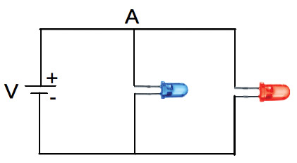
FIGURE 2. Two LEDs of different colors, driven in parallel by a power supply.
Circuit Junctions
To begin answering these questions, let’s discuss a basic feature in many electronic circuits: a junction, which is a place where two or more wires (or connections) come together. Take a look at the circuit in Figure 3, where a 9V supply is driving two resistors, connected in parallel to it and each other.
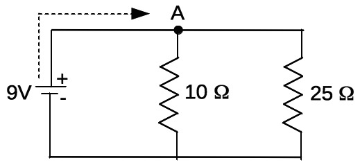
FIGURE 3. The resistor analog of Figures 1 and 2, emphasizing the current junction at A.
When analyzing this circuit, one can imagine a current coming from the positive lead of the battery in the direction of the dotted arrow as it traverses the wire. The question is: What does the current do when it comes to the junction at point A?
As you ponder your answer, know that whatever current flows into a junction must also flow out, as junctions do not store or otherwise “hide” current. So, if 1.5A flows into a junction, 1.5A must flow out.
In the circuit, the 10Ω and 25Ω resistors are in parallel, and in combination, they’ll form a 7.15Ω resistor. Using Ohm’s Law (I=V/R), the total current drawn from the battery will be I=9V/7.15Ω=1.26A. This means 1.26A will flow from the positive battery terminal and into the junction at A. So, what happens to it now?
It splits. Some will flow through the 10Ω and some will flow through the 25Ω, but in what amounts? We know that “current follows the path of least resistance,” so does this mean all of it will flow through the 10Ω? Or, will some flow through the 25Ω too?
Since “what flows in, must flow out,” we know that the sum of currents through the 10Ω and the 25Ω must equal 1.26A, for these are the only two paths for the current exiting the junction. Since the 10Ω and 25Ω are in parallel, they both have the same voltage across them (9V here). Thus, the current through the 10Ω will be (from Ohm’s Law) I=9V/10Ω=0.9A, and that through the 25Ω will be I=9V/25Ω=0.36A.
Note that 0.9A+0.36A=1.26A. So, indeed current flows through both resistors, but 2.5 times more flows through the smaller 10Ω resistor than the larger 25Ω resistor.
I like this result as it emphasizes how current and resistance are inverses as per Ohm’s Law. It gives us a mental grasp on the meaning of this sacred law: At a given voltage, more current will flow through paths of smaller resistance; this provides our first hint about how junctions behave. So, perhaps our adage could be changed to “current follows the path of least resistance, but in inverse proportion to the resistance of the path.”
Albert Einstein was famous for doing “gedanken” experiments, or experiments of pure thought. Let’s do one here to further think about junctions.
Suppose we put a very low resistance (let’s say 0Ω) jumper wire across the 15Ω resistor, and add the 50Ω resistor as shown in Figure 4. What would happen to the current now?
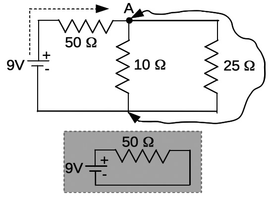
FIGURE 4. The gray inset is the equivalent circuit, if a zero ohm jumper wire were inserted as shown.
Well, now we have a three-fold junction at A. Current flowing out of the battery travels through the 50Ω on its way to the junction, where it will flow out, and possibly into 1) the 10Ω; 2) the 25Ω; and/or 3) the jumper wire. The current that flows into the junction will “see” all three paths. Which will it choose?
In this extreme gedanken case (involving a 0Ω wire), all current will flow down the 0Ω path. It’ll behave as if the 10Ω and 25Ω weren’t even present, as absolutely no current will flow through them, for why would current “choose” to flow through any resistance at all when it can flow through a 0Ω path?
The circuit will behave like the inset circuit in Figure 2, and the battery will supply I=9V/50Ω=0.18A to it. We added the 50Ω resistor to avoid (even in a thought experiment) shorting out the power supply, which is yet another experience with Ohm’s Law. Without the 50Ω resistor, the jumper wire would present 0Ω across the 9V supply, and the current demand would be I=9V/0Ω which “equals” ∞, blown fuses, overheating components, melting wires, smoke, and the like.
If the 0Ω resistance was increased — even by a minute amount — we’d then start to see the current distribute itself along all three paths. Neat, huh? Let’s get back to the circuits with the light bulbs and LEDs now.
The Light Bulbs
With the light bulbs of Figure 1, we’ll start with their labels: a 1W and a 2.5W. The “wattage” likely indicates the brightness of the bulb (as per its specification, if run at 6V). We expect the 2.5W bulb to glow brighter than the 1W bulb. How does this fit in with the circuit junction at A?
Along with Ohm’s Law, there’s a power equation in electronics, commonly stated as P=IV or P=I2R. Note again more mathematical combinations of I, V, and R (but different than Ohm’s Law). The P here is “power” and is in watts, given that I is in amperes and V is in volts. We focus on power here because that’s what light is: some amount of energy-per-second (or power) flowing away from the bulb.
So, on the one hand, since the bulbs in Figure 1 are in parallel (or at the same voltage), P=IV means the more current, the brighter the bulb since P is proportional to I at a given V. This means more current should flow through the 2.5W bulb as it leaves the junction, since we expect it to be brighter.
On the other hand, using P=I2R, we see a stronger (squared) dependence on current, but now there’s an R in there, so does a higher resistance lead to move power at a given current? However, a higher resistance would allow less current flow (I and R are inverses). What gives?
We know that light bulbs work when a resistive filament inside of them gets so hot that it glows. So, let’s start by putting an ohmmeter across the leads of a bulb to measure the resistance of its filament. The 1W bulb gives about 5.5Ω, and the 2.5W bulb about 3.9Ω. So, the filament in the higher wattage bulb has less resistance.
In Figure 1, doing a similar analysis for Figure 3, we’ll find that 1.5A flows through the 2.5W bulb, and 1.1A through the 1W bulb. Thus, about 1.3 times more current will flow through the 2.5W bulb as it leaves the junction than will flow into the 1W bulb.
Here, P=IV indeed provides a clear picture of why the 2.5W bulb is brighter: its filament has less resistance, and at a given voltage, it draws more current (via Ohm’s Law), and since light power (P) is proportional to I, the bulb will be brighter. More current leaving the junction at A will “choose” to flow through the 2.5W bulb than through the higher resistance of the 1W bulb.
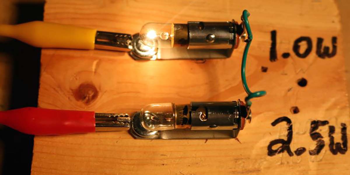
To test all of this, I fastened two bayonet-style bulb holders onto a scrap piece of wood (as shown in Figure 5) to hold the 1.0W and 2.5W miniature bulbs. The red clip lead is from the positive of the power supply, and the yellow is to ground. The white, lead, and (soldered) green wire complete the parallel configuration. The 2.5W bulb is clearly brighter. This might all seem obvious at this point, but there’s a bit more to these light bulbs. Let’s dig deeper.
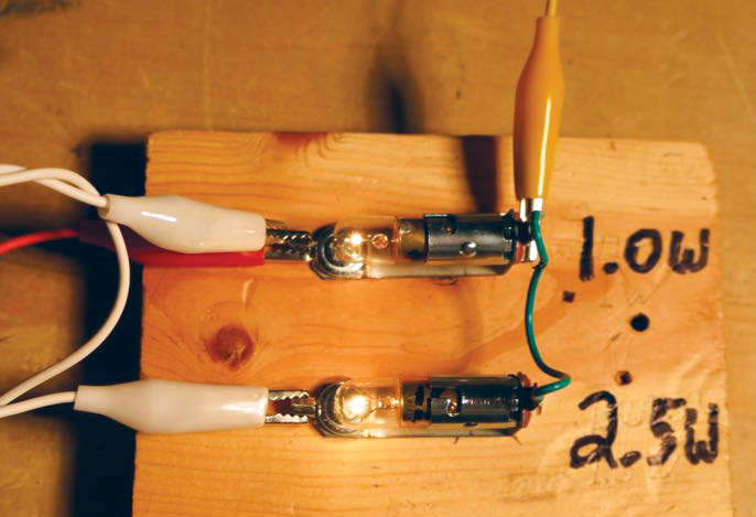
FIGURE 5. Two bulbs in parallel. The 2.5W bulb is clearly glowing brighter than the 1.0W bulb.
Current vs. Voltage
In electronics research, a useful first step in understanding an electrical device is to acquire “I-V” data for it: “I” stands for current, and “V” stands for voltage. Such data means to apply a given voltage across a device, then measure the current it draws at that voltage. If this is done for a sequence of voltages — for example, from 0 to 10V in steps of 0.5V — a data set can be obtained, then graphed.
A simple I-V data acquisition circuit is shown in Figure 6.
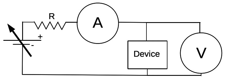
FIGURE 6. By slowly ramping the voltage of the power supply, this circuit would allow one to acquire a voltage vs. current dataset for the "device."
You’ll need two meters to do this: the one labeled “A” is an ammeter (or a “voltmeter” set and wired in current measuring mode); and the one labeled “V” is a voltmeter (or a second “voltmeter” set and wired in voltage measuring mode). A device to be characterized is inserted for the “device” in the figure. The arrow through the battery symbol means an adjustable voltage supply, and the resistor R is used to protect the unknown device, in case it itself has a very low resistance. (I actually omitted it in the work here.)
If you build this tester, it’s fine to cobble it together using clip-leads and alligator clips. Just try to keep the wires neat, and work carefully to insert your meters properly. I’d build the circuit first and be sure the bulb glows. Then insert the ammeter, again being sure the bulb glows and that you see a current reading. Lastly, clip the voltmeter across the bulb (and be sure it still glows).
In Figure 7, I-V data is shown for a resistor placed in the device of Figure 6.
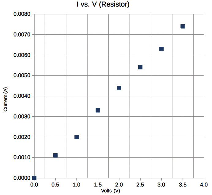
FIGURE 7. Current vs. voltage data acquired for a resistor inserted for the "device" of Figure 6.
I turned the voltage on my power supply all the way down to zero, and recorded zero current. I then turned the voltage up to 0.5V and read about 0.0011A, and so on. I typed the data into a two-column spreadsheet and made an XY-scatter graph.
From the graph, I see that the higher voltage placed across a resistor, the more current it draws. This sounds a lot like Ohm’s Law, in that I=V/R (I is proportional to V), and since the data looks linear, I’ll find a “trend line” for it. When I did so, the slope came out to be 0.00212A/V. What of this?
Well, since I=V/R, this number must be 1/R, so 1/R=0.00212 A/V, or R=471Ω. Indeed a 470Ω resistor was inserted for the device. We verified that Ohm’s Law holds nicely for a resistor, and were able to use the I-V data to determine the actual resistance of the device. Electrical devices showing a linear I-V curve for DC voltages are called “ohmic.”
Now, what about the incandescent light bulb? I-V curves for both are shown in Figure 8, and they are obviously not ohmic over their entire operating range.
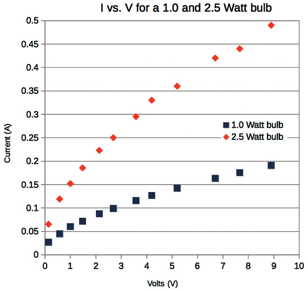
FIGURE 8. Current vs. voltage data acquired for 2.5W and 1.0W light bulbs.
One might identify a few linear ranges, but clearly their resistance (or the slopes of their I-V curves) is not constant. This is due to heating of the filament as a bulb glows. Ohmic resistance generally goes up with temperature, owing to increasing thermal vibrations of the crystal lattice making up the filament material itself. The vibrations make it harder for electrons to pass (presenting them with more resistance).
So, what would we see in the circuit of Figure 1? Well, supposing we operated the circuit at 6V, let’s examine an I-V curve for each bulb. From each curve, we’d determine what current each draws at 6V and use Ohm’s Law or R=V/I to compute the resistance of each. From Figure 8, the 2.5W bulb is consuming about 0.38A at 6V, while the 1.0W bulb is consuming about 0.15A. From this, the resistance of the 2.5W bulb is R=6V/0.38A=15.7Ω and 6V/0.15A=40Ω for the 1W bulb. Note how the resistance of the “hot” filaments has gone up relative to the “cold” ohmmeter measurements above.
Thus, at 6V, we may think of the two bulbs as the resistors in Figure 3, and using the same analysis, find that a current of 0.53A will flow into the junction and will split into 0.38A for the 2.5W bulb and 0.15A for the 1W bulb. The power dissipated by the 2.5W bulb — some into light and most into heat — would be P=(0.38A)2(15)=2.1W, and that by the 1W bulb P=(0.15A)2(40)=0.9W. Indeed the 2.5W bulb draws more current from the junction, and will glow brighter (Figure 5).
The wattages quoted by the manufacturer are likely the “nominal” ones used to maximize their usage lifetime. (We could drive the bulbs a bit harder here.) However, we see that in actual operation at 6V, the resistance of the 2.5W bulb is still lower than that for the 1W bulb. Thus, the 2.5W bulb will draw more current, and glow brighter (P=IV).
Just for fun, suppose the bulbs are wired in series, as shown in Figure 9.
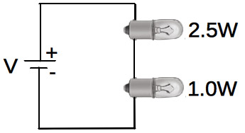
FIGURE 9. Two light bulbs with different power ratings, driven in series by a power supply.
Series means the same current travels through each bulb. Such circuits do not have any junctions. When operating the circuit at 6V, the total measured current draw was 0.13A, with 5.1V across the 1W bulb and 0.9V across the 2.5W.
Note these voltages add to 6V (as they must), with the larger voltage drop across the 1W bulb (V=IR, and it has the higher filament resistance). The power dissipated by the 2.5W bulb will be less than that of the 1.5W bulb at this current, owing to its smaller filament resistance (remember P=I2R).
Thus, in series, the bulb with the higher watt rating will actually glow dimmer than that with the smaller watt rating as can be see in Figure 10, where the 2.5W bulb is barely glowing relative to the 1W bulb.
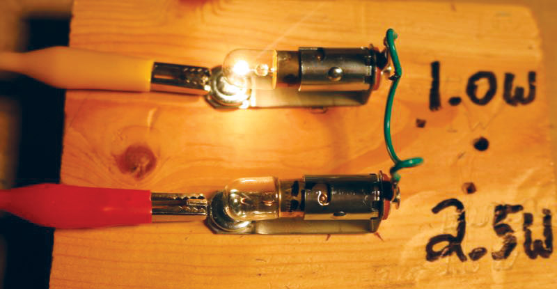
FIGURE 10. When driven in series, the bulb with the higher watt rating glows very dimly.
Should we ask the manufacturer for a refund? No, sorry. Bulb wattage ratings assume parallel connections. The same holds for incandescent light bulbs we use in our homes at 110V AC. A 100W bulb, for example, would glow dimmer than a 60W bulb in a series AC circuit.
The LEDs
We’re now well equipped to handle the LED circuit. We’d still like to know what will happen if the circuit in Figure 2 was wired up (as shown in Figure 11).
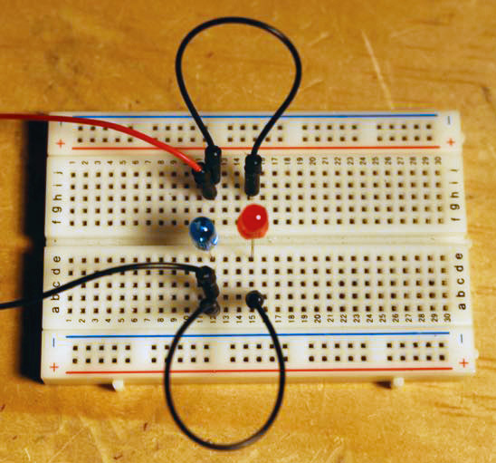
FIGURE 11. The breadboarded circuit of Figure 2.
Let’s approach it as a research scientist and look straight to the I-V curves for a red and a blue LED, shown in Figures 12 and 13. Here, the black dots are the actual I-V data points, and the straight lines are trend lines to aid the eye.
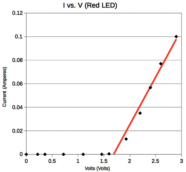
FIGURE 12. The I-V curve for a red LED.
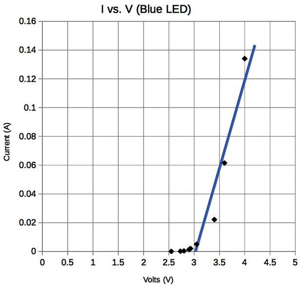
FIGURE 13. The I-V curve for a blue LED.
Since LEDs are diodes, we see a typical “diode” I-V curve: no significant current for a few volts, then suddenly a rather rapid “turn on” and surge of current that gets comparatively very large for small increases in the driving voltage. Looking carefully, we see that the red LED turns on (starts to draw current) around 1.6V, and the blue at around 3V. To figure out the LED circuit in Figure 2, we need to study the I-V curves carefully, and keep in mind that the two LEDs are wired in parallel; meaning the voltage across each will always be the same.
We know the blue LED won’t turn on until 3V develops across it, and if we look at the red LED’s I-V curve, by 3V. Not only would it be on, it would be consuming around 0.1A. This is quite a large potentially damaging current for a miniature LED.
When running this circuit, the red LED was quite bright already by 2.5V, and I could only begin to see the faintest light emerging from the blue LED at about 2.7V. Owing to the steep slope of the red LED’s “on” curve, however, small increases in driving voltage led to rather large increases in current. For the sake of the red LED, continually upping the driving voltage trying to reach 3V would not be a good idea. Thus, the circuit behavior in Figure 2 is best described as a case where — within reasonable operating specifications — the red LED will light, but the blue will not.
I hope you see the advantage of the I-V curves for something “exotic” like an LED. The steep slope of the I-V curve is readily revealed, helping to explain why the blue LED in Figure 11 stays off unless we make the red LED really sweat.
Challenges
Here are a few things for you to work on. First, the turn-on voltage for a green LED is lower than that for blue. See if you can acquire an I-V curve for a green LED, and predict how it might behave in Figure 11 instead of the blue.
Second, the emission wavelength of an LED can be discovered using the trend lines found for the “on” region of an LED’s I-V curve to precisely determine the turn-on voltage of an LED (use the trend line equation to find what V makes I=0).
From this V, find the emission wavelengths for a green, blue, and red LED. (Hint: For a photon, E=hc/λ, where E is the photon’s energy, h is Planck’s constant, c is the speed of light, and λ is its wavelength. Note also that E is related to the turn-on voltage of an LED). Compare your results with those on the Wikipedia LED page.
Third, the slope of the blue LED’s trend line is 0.122Ω and for the red is 0.08Ω. Thinking of the LEDs then loosely as “resistors” of these values, what behavior would you expect as the voltage was slowly turned up from zero if they were connected in series?
Can you explain Figure 11’s behavior based on what you now know about junctions and these numbers?
Fourth, acquire a “varistor” and “resettable fuse” (see the Parts List) and study I-V curves for them.
Conclusions
I hope you saw the value in acquiring I-V curves for the light bulbs, and particularly for the LEDs. I always find it enjoyable to figure out some way of generating raw data that I can then study to learn more about something.
My original motivation for this article came years ago, when I was working on a project with different colored LEDs.
Putting them in parallel across a power supply was simple but puzzling because the different colored LEDs wouldn’t light properly.
I now know why, and it appears that driving (different colored) LEDs in parallel directly from a DC power supply was not a good idea.
Lastly, by seeing the steepness of an LED’s I-V curve, hopefully you see why LEDs are most often used in conjunction with a series resistor in an actual circuit. Typically, a safe operating current for an LED is determined, and the value of the resistor is chosen to drop enough voltage across itself (at that current as per V=IR) to limit the voltage drop across the LED to some safe level. NV
Parts List
2.5W, Trade #1810 bulb, 9527T186
1.0W, Trade #57 bulb, 1505K21
mcmaster.com
Mini-bayonet base lamp socket
Mini jumpers
Blue, green, and red LEDs
Jumper wires
Solderless breadboard
Adjustable power supply (various options)
Varistor (be sure to purchase a varistor that works within the range of your power supply)
Resettable fuse
Two volt meters with current measuring capability
harborfreight.com