In the beginning there was only noise, but humans have learned to make their own electromagnetic crackles and pops with a device that is as much as possible ... empty! Radio and vacuum tubes grew up together from their genesis a century ago, but their history was not a clean, step-by-step process. Theory and experiment took turns leapfrogging each other, mixing sudden discoveries and steady refinements. Their story begins in the Age of Steam.
The Dawn of Radio
The story of radio really begins in 1830, when Joseph Henry (for whom the unit of inductance is named and who is shown in Figure 1) observed that energy could be conducted from one coil to another by mutual inductance.
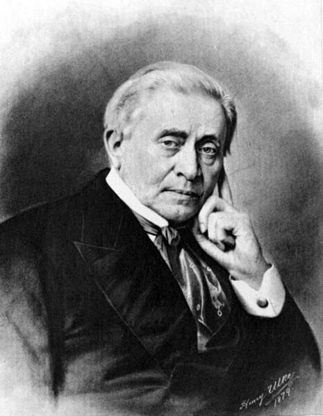
FIGURE 1. Joseph Henry first observed the transfer of energy by induction in 1830. Later he became the Smithsonian Institution’s first director.
Michael Faraday (whose name is borne by the unit of capacitance, the farad) observed it a year later. This discovery was one of many in electricity and magnetism, culminating in James Clerk Maxwell’s 1865 paper describing electromagnetism mathematically.
Later in 1881, Oliver Heaviside simplified that description into the form known today as “Maxwell’s Equations.” (Heaviside is also credited as being the first to speculate that a charged layer above the Earth (now known as the ionosphere) is responsible for the long-distance propagation of radio waves.)
Also in 1865, the first system capable of sending messages without wires was demonstrated by Virginia dentist Mahlon Loomis. While he received a patent for his system in 1872, Loomis did not understand how it worked and was not able to make commercial use of it.
In the mid-1880s, development of what we would now consider “real radio” began in earnest. While experimenting with nerve impulses in 1885, Edouard Branly invented the coherer — a tube filled with fine metal filings sketched in Figure 2 — to detect faint electrical signals.
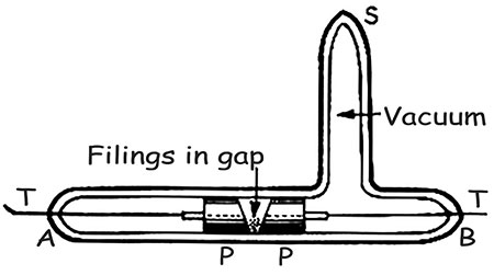
FIGURE 2. The coherer is basically a tube containing iron filings between two electrodes. Electromagnetic fields cause the resistance through the filings to decrease.
Adapted from "A History Of The Marconi Company", by W.J. Baker, Methuen (1970)
The filings “cohere” or move closer together in the presence of an electric field (such as a radio signal), lowering the resistance through them. In 1894, the coherer was refined by Oliver Lodge, whose tikker converted the changes in resistance to audible clicks.
At the same time, physicist Heinrich Hertz was making significant theoretical strides in the understanding of radio waves. He transmitted signals across his lab in 1887 as UHF radio waves. In the same year, Michelson and Morley published the results of their experiment showing electromagnetic energy (in the form of light) travels without requiring an all-pervading “aether.”
While experimenting with light bulb filaments in 1883, American inventor Thomas Edison observed that electric charge would travel from a heated metal surface towards a more positively-charged electrode. He patented the Edison Effect (based on thermionic emission), but was focused on developing electric lighting and it fell to Ambrose Fleming to apply it.
Fleming worked with thermionic emisson for a number of years, discovering that the uni-directional current flow between the two electrodes could be used to sense (or detect) radio waves. (During this period, J.J. Thompson determined that the electric charges were components of atoms, which were named electrons.) In 1904, Fleming received a patent for a two-electrode tube, known as a diode. At best, however, the diodes and coherers could merely convert signals from one form to another (such as waves to clicks) and could not increase their strength. This greatly limited the range of early wireless systems.
Amplification became possible when Lee de Forest discovered that placement of a charged wire between the diode’s two electrodes affected the flow of current between them. His early Audion tubes (see Figure 3) had just a single wire for control, but it was soon determined that a mesh or grid of wires improved the tube’s detection sensitivity.
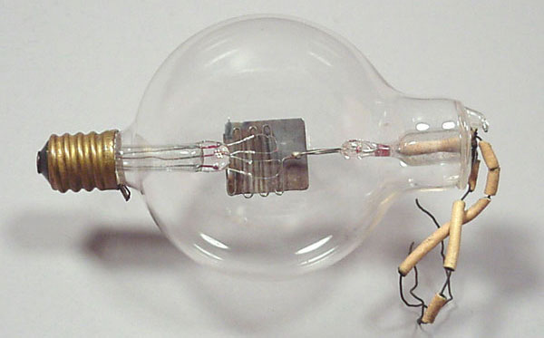
FIGURE 3. The Audion was the first device capable of amplifying a signal and had three elements: a filament (cathode), a control grid, and a plate. Photo courtesy of Mike Schultz, www.uv201.com.
Patented by de Forest in 1906, the three-electrode tube, or triode, could use a small grid voltage to control the much larger currents that flowed from the heated electrode (the cathode) to the collecting electrode (the plate), effectively amplifying the small input signal. With the Audion’s ability to amplify as well as detect, the modern era of radio and electronics had arrived.
VACUUM TUBE TERMINOLOGY
Cathode — The element from which electrons are generated.
Control grid — A grid designed to perform amplification.
Element — One of the tube’s electrodes that performs an electrical function.
Envelope — A tube’s outer shell.
Filament or Heater — The element that heats the cathode.
Gassy — A tube whose vacuum has been contaminated by gas.
Getter — An electrode that absorbs gas molecules to preserve the tube’s vacuum.
Grid — An element that acts to control electron flow from cathode to plate.
Octal — A tube with eight pins.
Pins — The external connections to a tube’s elements.
Plate — The element at which electron flow terminates.
Screen grid — A grid designed to perform protective or isolation functions.
Valve — The English term for a tube.
Turning on Radio
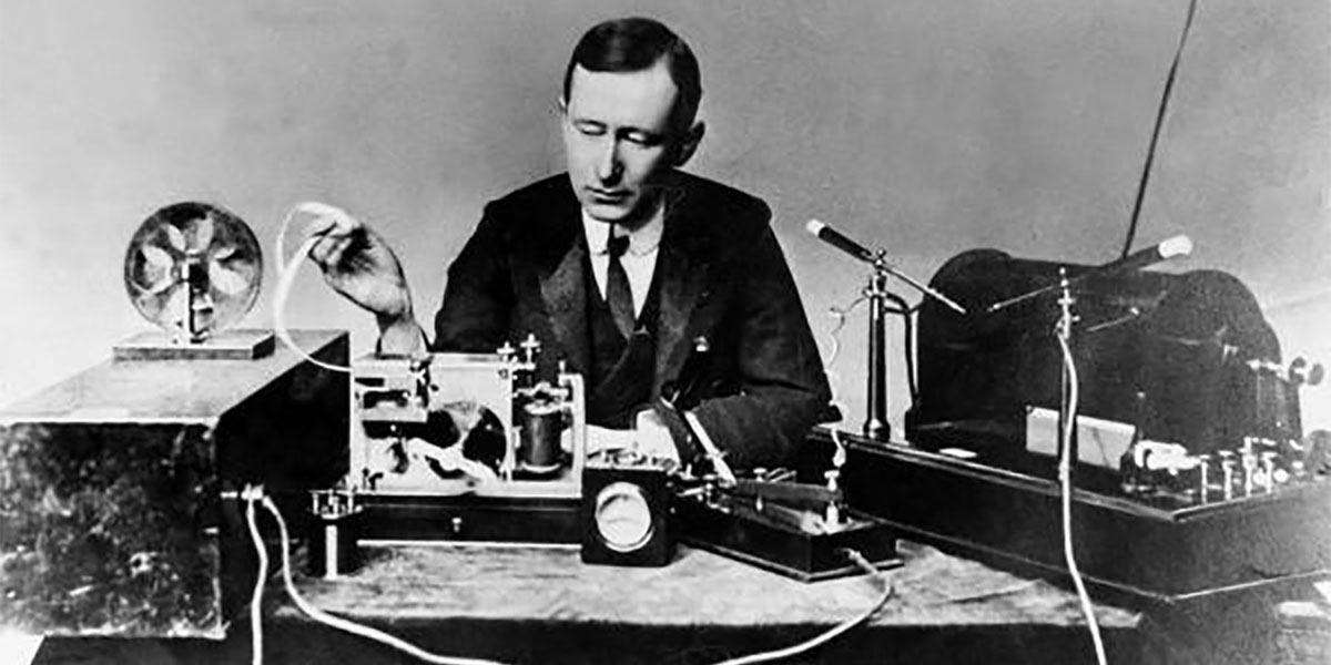
In 1894, the experiments of Hertz and others attracted the attention of a young Italian by the name of Guglielmo Marconi. He became fascinated with the idea of sending messages without wires and began a series of experiments based on what he’d read in the 19th-century equivalents of Nuts & Volts. Working in the village of Salvan, Italy, the range of his wireless messages increased slowly until the transmitter and receiver were completely out of sight of each other. Remember that wireless technology was exotic stuff in Victorian times, much as molecular biology is today!
After seven years of development, in 1901, as the Wright brothers were building their first airplanes, Marconi set up a receiver on Signal Hill in Newfoundland, Canada. On December 12th, he was able to receive a single letter, “S,” transmitted from Cornwall, England and the radio race was on. Although others such as Tesla also demonstrated wireless transmission, Marconi was the first to successfully commercialize his inventions and so he is known as the “father of radio.”
Cutting-edge radio technology of the day was Morse-based, of course. Because there were no sources of steady radio-frequency (RF) signals, an arc was used. As you can hear on an AM broadcast receiver, an arc such as a lightning bolt contains energy on a wide range of frequencies — from DC through light! Marconi’s transmitters generated powerful arcs whose RF energy was extracted and radiated by antennas tuned to frequencies below 100 kHz. A rotary spark station of yore generated many kilowatts of power — not only strong RF signals, but deafening roars and crashes of sound, too!
There were numerous other engineers and experimenters improving radio technology. Two of the best-known are Reginald Fessenden and Valdemar Poulsen. Spark transmitters were extremely inefficient and spread what RF they did generate across the radio spectrum. Poulsen reduced the transmitted signal’s bandwidth by connecting a tuned circuit across the arc. This allowed many more stations to share the airwaves and improved reception distances dramatically.
A former assistant of Edison, Fessenden’s most significant contribution of many was to construct continuous-wave (CW) transmitters that operated on a single frequency. Figure 4 shows the dramatic improvements in efficiency achieved by changing from spark signals to CW.
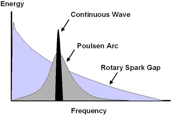
FIGURE 4. Spark transmitters transmitted energy over a very wide bandwidth. The Poulsen arc dramatically reduced wasted signal power. Continuous Wave (CW) transmitters are the most efficient of all.
The RF was generated by high-frequency alternators designed by General Electric engineer E.F.W. Alexanderson. Operating at about 50 kHz, alternator-based transmitters were quite an improvement and soon most stations were using them at frequencies from 15 to 60 kHz. Fessenden used one to make the world’s first broadcast of speech and music on Christmas Eve, 1906.
The airwaves were not limited to commercial and military stations. As radio became widespread, so did experimentation by private individuals, some of whom formed the Radio Club of America in 1907. It is estimated that by 1910 there were as many as 10,000 wireless enthusiasts building transmitters and receivers! Encouraged and informed by magazines such as Hugo Gernsback’s Modern Electrics, several hundred thousand citizens were engaged in some form of radio experimentation by the start of World War I. Licensing of these amateurs or “hams” began in 1912 and the American Radio Relay League was formed in 1914. Both the RCofA and ARRL are still in existence today!
Broadcasting and Riding the Short-Waves
Radio captivated the public interest in the early 1900s much as the Internet did a century later. Broadcasting got its start in 1909 as Charles Herrold began transmitting from his technical school in San Jose, CA. After the war ended, interest in receiving broadcasts soared. KDKA in Pittsburgh, PA received the first broadcasting license in 1920 and Herrold’s station became KCBS the following year.
Early broadcasters used new amplitude modulation (AM) technology, allowing them to provide speech and music to the listening public. AM broadcasting was made possible by the new and powerful vacuum tubes developed for the military during the war. These tubes could develop powerful signals of hundreds (!) of watts on the long-wave bands between 545 and 220 meter wavelengths (1,350 to 550 kHz). By 1923, broadcast programs were heard every evening throughout the United States.
Before 1920, most radio engineers were convinced that the longer the wavelength of the radio wave (or the lower its frequency), the greater its range. Thus, the most important radio services — military, commercial, and broadcasting — preferred radio wavelengths of hundreds of meters. In 1923, the first “frequency bands” were created, relegating amateurs to the “worthless” bands with meager wavelengths of 200 meters or less (1.5 MHz or higher).
This turned out to be good for the amateurs or “hams.” They rapidly discovered that the short-waves supported communication over extremely long distances. (The secret turned out to be signal reflections from the ionosphere and ground.) In November of 1923, amateurs made the first two-way, short-wave transmissions across the Atlantic between 1BCG (a station in Massachusetts sponsored by the Radio Club of America) and Leon Deloy, F8AB in France. Distance records fell rapidly with the only frequency limits being those of vacuum tube technology. New tubes and receivers were vastly more sensitive than before, allowing communications around the world with powers of a few watts.
Soon, the services that had clamored for long-wave assignments were demanding short-wave spectrum from the new Federal Radio Commission. The late 1920s were a tumultuous time of rapidly advancing technology as radio permeated every aspect of modern life. Nations found themselves in competition for spectrum access as signals routinely ignored national boundaries. This grand awakening culminated in the formation of the International Telecommunications Union in 1934 and created modern radio spectrum management. At home, the Communications Act of 1934 created the Federal Communications Commission (FCC) which administers all telecommunications activity in the US.
Edwin Armstrong
No discussion of early radio would be complete without the inventions of Major Edwin H. Armstrong. With the possible exception of Marconi, no other individual had such a large impact on the development of radio in so many areas.
Armstrong was responsible for three major advances in the radio arts (and many smaller ones). The first was the regenerative receiver patented in 1914 by Armstrong while a junior in college. The “regen” was the first electronic circuit to use feedback in order to increase sensitivity (the ability to receive weak signals) and selectivity (the ability to distinguish between signals). Figure 5 shows the schematic of a regenerative receiver.
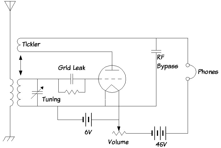
FIGURE 5. The circuit of a regenerative receiver circuit. Positive feedback through the tickler coil dramatically increased receiver sensitivity and selectivity.
By allowing the receiver to operate at the edge of oscillation, even extremely weak Morse signals could be detected.
His patent of 1918 was even more important. The superheterodyne receiver converts signals from one frequency to another by mixing them with another frequency and then selecting from the sum and difference frequencies (heterodynes) that result. The superheterodyne can receive a wide range of frequencies by converting them to a single frequency (the intermediate frequency or IF stage) where high-gain amplifiers and filters can be employed. The “superhet” design is the basis of nearly all radios in use today, nearly 90 years later!
Third was the development of wide-bandwidth frequency modulation (FM) transmission and reception in 1935. Armstrong had learned that nearly all static and noise is amplitude-modulated. Attempting to remove noise from an AM signal would also destroy the desired signal. His solution was to change the method of signal modulation from AM to FM and to increase the bandwidth of the FM signal for good fidelity. He succeeded spectacularly as fans of FM radio know. FM signals are the most common in the world, with the exception of mobile phone transmissions. Armstrong also invented multiplexed FM, the technology used for stereo transmission.
100 Years Down the Tube
So much from something so empty! The vacuum tube’s story is also the story of the beginning of the Industrial Age. Just as steam power extended our physical abilities, radio and electronics enabled us to extend our communications abilities. While the transistor and IC are the electronic “second stage,” the vacuum tube was indubitably the rocket that lifted us off the launching pad. NV
FURTHER READING
Early Broadcast Radio History — earlyradiohistory.us
200 Meters and Down by Clinton B. DeSoto, published by the ARRL (www.arrl.org) — A history of amateur radio until the late 1920s.
Wikipedia — www.wikipedia.org — Many excellent entries on radio-related topics.
Jurassic Radio — www.oldradio.com/archives/jurassic — Detailed stories on early radio technology.
Empire of the Air: The Men Who Made Radio by Tom Lewis — The lives and battles of Lee de Forest, Edwin Armstrong, and David Sarnoff.
Edwin Armstrong — users.erols.com/oldradio — Detailed information on Edwin Armstrong’s experiences and his contributions to radio.
ARRL — www.arrl.org — The National Association for Amateur Radio.
Radio Club of America — www.radioclubofamerica.org — The world’s oldest radio organization.