Most digital circuits are limited to outputting zeros and ones. And while they can do this quickly and efficiently, there are many more types of signals in the real world that require something other than zeros and ones.
This article will briefly examine a number of methods of creating sine waves, and other waves, from digital values. The goal of this article is to familiarize the reader with a number of different techniques rather than to describe those techniques in detail.
Filtering a Square Wave
The simplest method of converting a square wave to a sine wave is by filtering. Basically, a square wave consists of a fundamental frequency with a lot of higher harmonics. If the harmonics can be removed, then a sine wave of the fundamental frequency remains. This is easier said than done because simple passive filters are not too efficient.
However, a reasonable sine wave can be created with a three-stage RC (resistor-capacitor) filter that is shown in Figure 1.
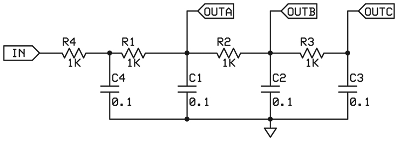
FIGURE 1. Basic four stage filter. The component values will vary according to the desired frequency. The frequency here is about 1,500 Hz.
Photos 1, 2, and 3 show the result of filtering a square wave at outputs A, B, and C, respectively. Photo 1 is the result of two stages of filtering (note different amplitude scale).
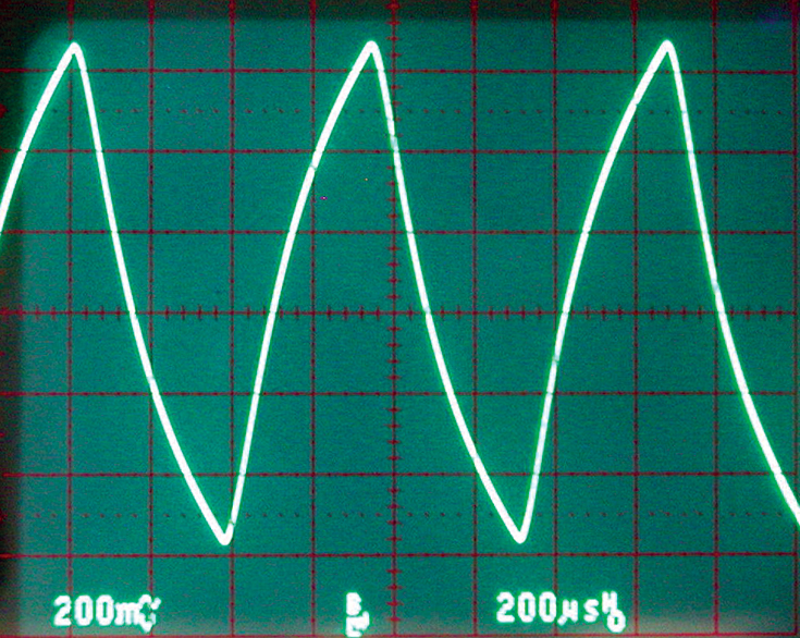
PHOTO 1. A filtered square wave from Figure 1, output A. Not a very good sine wave.
It is certainly not a very good sine wave. Photo 2 looks more like a triangle wave than a sine wave.
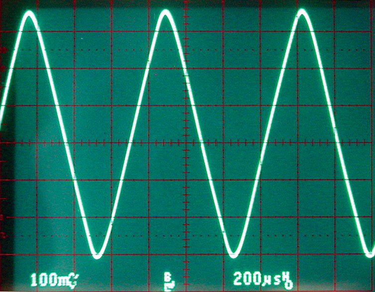
PHOTO 2. The third stage (output B) is better, but still not a very good sine wave.
But it is certainly better than Photo 1. Photo 3 is actually a pretty good sine wave. The measured distortion is only a few percent. Not too bad for four resistors and four capacitors.
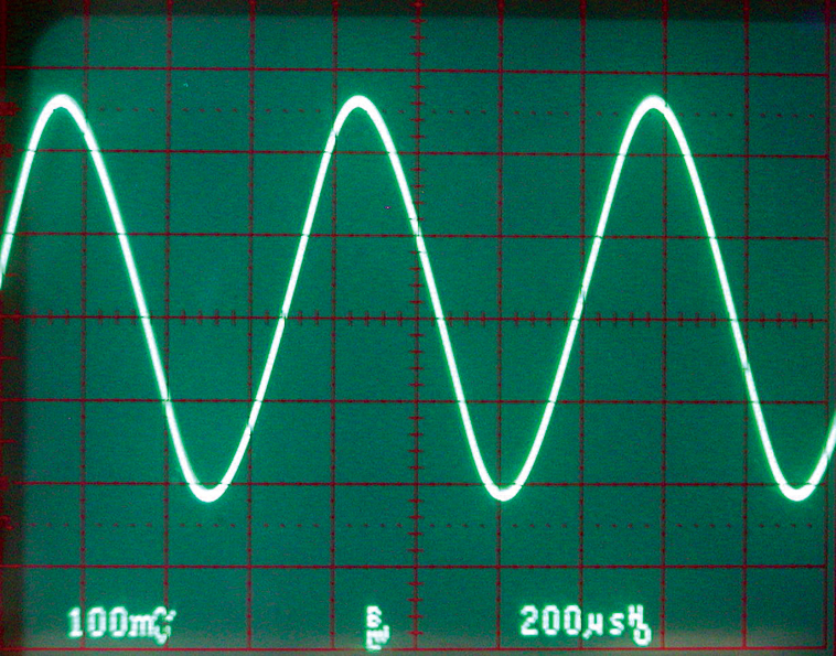
PHOTO 3. After four stages, (output C) a pretty good sine wave is created. Distortion is only a few percent.
Note that the amplitude of the final filtered square wave is about 0.5 volts. This is only 10% of the original amplitude of 5.0 volts. It becomes clear that filtering with passive components reduces the amplitude.
Another problem with this approach is that it is frequency specific (about 1,500 Hz here). A higher input frequency will result in smaller final amplitude. A lower input frequency will not be filtered as well and will not be as good a sine wave. However, if all you need is a fixed frequency sine wave, this method can be very effective.
Active Filtering and Switched Capacitor Filters
You can certainly use active filters (filters incorporating an op-amp) to convert a square wave to a sine wave. They have the advantage of maintaining the amplitude of the signal but are fairly complicated and require a number of additional components. They are also limited to a fixed frequency response. This restricts their usefulness.
Switched capacitor filters are a form of an active filter. However, by switching capacitors on and off, the parameters of the filter can be modified by changing the switching rate. This makes the filter extremely useful for digital applications for a number of reasons. The first (already mentioned) is that the filter can be modified by changing the switching frequency. Another is that the switching signal is usually a digital clock with typical logic levels. This is easy to generate and control from a digital circuit.
There is also a direct relationship between the filter cutoff frequency and the clock/switching frequency. This is usually 50 or 100. What this means is that the clock frequency is generally exactly 50 or 100 times the cutoff frequency. (For example, for a filter with a cutoff frequency of 1 kHz, the clock would have to be 50 kHz or 100 kHz.) So, you can tune or sweep your filter over a wide range of frequencies very easily. The number of additional components needed to implement this approach can be very small (see Figure 2).
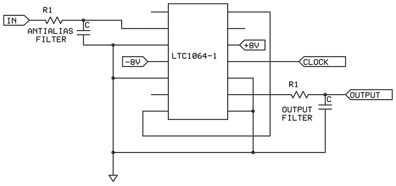
FIGURE 2. A switched capacitor filter may only need an input anti-aliasing filter and an output smoothing filter to operate properly.
However, probably the strongest feature of these filters is that they can have extremely sharp cutoffs. This means that they can remove the higher harmonics of a square wave very effectively which leaves a pure sine wave. The “order” of the complete filter shown in Figure 1 is four. That is, with four capacitors it can reduce the higher frequencies at a rate that is four times a single capacitor (crudely speaking).
Figure 2 incorporates an eighth order filter, and filters up to the 10th order are available from Linear Technology. (Maxim is another manufacturer and National Semiconductor marketed the first popular switched capacitor filter, the MF-10. This is still available for a couple of dollars.) The LTC1064-1 shown in Figure 2 has a frequency response that is about 72 dB down at 1.75 times the cutoff frequency.
If the cutoff frequency is set to 1,000 Hz, then a signal of 1,750 Hz will be reduced by 72 dB or to about 0.025%. This makes a very good sine wave out of a square wave. (Note that we've been discussing only low-pass filters. Switched capacitor filters can be any type of filter: low-pass, high-pass, band-pass, and notch.)
There are a couple of negatives to switched capacitor filters. Often they require a negative voltage for operation (in addition to a positive voltage). They can exhibit a DC offset in the output of up to a few tenths of a volt. Since they are in the class of “sampled circuits,” they require an input anti-aliasing filter. However, this is usually just a simple RC filter.
The output consists of a stepped waveform (see Photo 4).
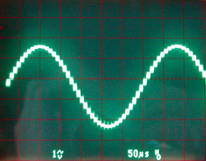
PHOTO 4. A switched capacitor filter produces a stepped waveform because of the sampled nature of the circuit.
This can also be fixed with another simple RC filter. Photo 5 shows the final result of a square wave that is filtered with a seventh order switched capacitor filter.
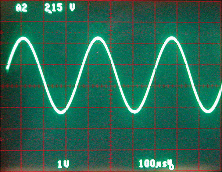
PHOTO 5. A simple RC filter after the switched capacitor filter creates a very good sine wave with very low distortion.
As you can see, it is a very nice sine wave. Photo 6 demonstrates this with the harmonics lost in the noise floor that is over 60 dB below the fundamental. This sine wave has less than 0.1% distortion.
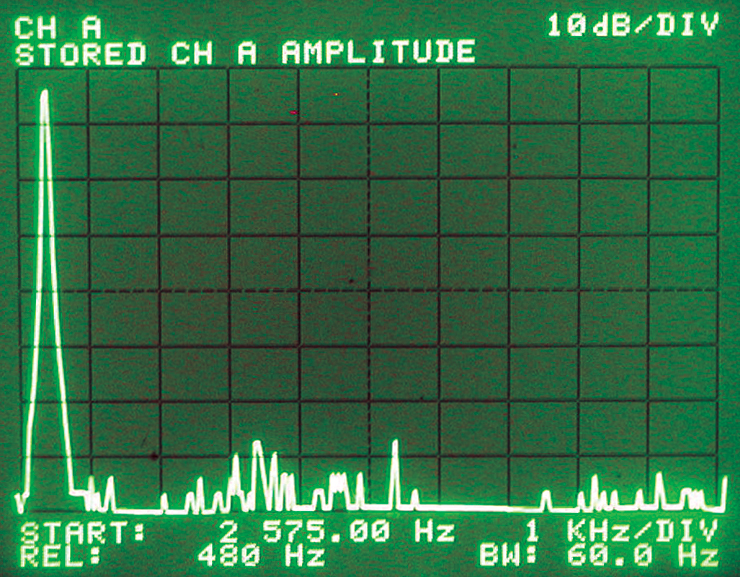
PHOTO 6. The spectrum of Photo 5 shows that the harmonics are lost in the noise floor of the instrument which is over 60 dB below the fundamental. The sine wave has less than 0.1% distortion.
Using a DAC
The traditional method of creating analog signals is by using a DAC (digital to analog converter). This takes a digital value (typically eight to 16 bits long) and converts it to an appropriate analog value. This approach also produces a stepped output signal and a simple RC filter can be used to remove the edges. With a 12 to 16 bit DAC, the output steps are so small that filtering is often not implemented.
You can make your own DAC for a few pennies. The basic circuit is shown in Figure 3 and consists of an “R-2R” ladder. With 1% resistors, you can go six to eight bits. With resistors matched to 0.1%, you can go 10 to 12 bits.
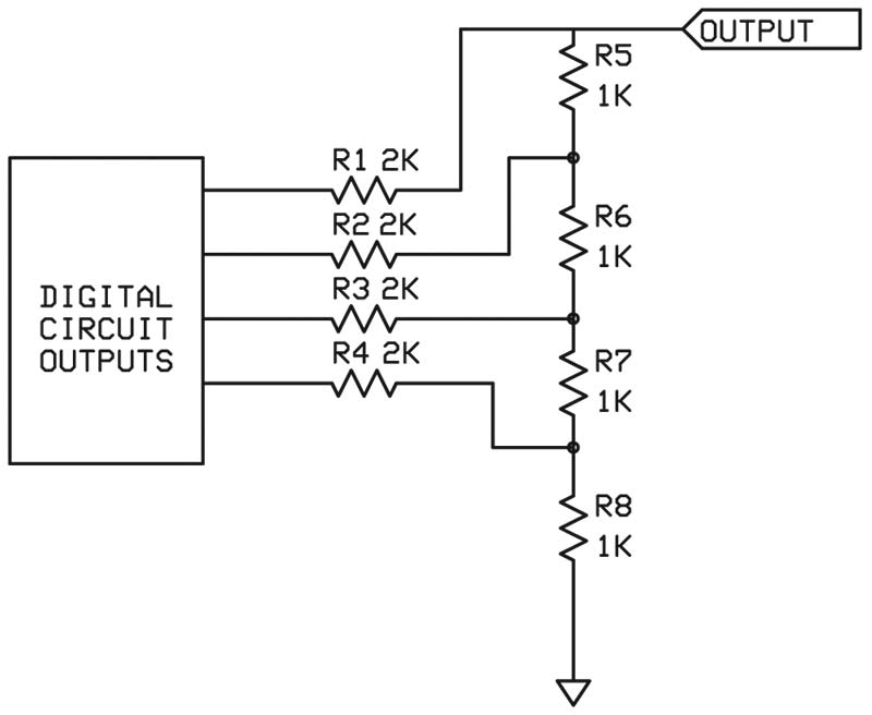
FIGURE 3. The standard R-2R ladder network can convert a digital word into an analog signal. With precision resistor matching, up to 10 bits can be implemented.
With a DAC, you can make any wave shape desired by outputting the proper value. Creating sine waves can be troublesome for small microcomputers because of the difficulty in creating the actual sine wave values. It is not a simple mathematical operation. For that reason, a look-up table is often incorporated. Of course, a look-up table can be created for any desired wave shape. It is not limited to a sine wave.
This look-up table can be internal or external to the microcomputer and it can be RAM (random access memory) or ROM (read only memory). If it's ROM memory, the wave shape can't be changed. However, if it's RAM memory, the wave shape can be easily changed by simply modifying the contents of the memory. Using an external RAM to hold the wave shape is the typical situation for an instrument called an Arbitrary Waveform Generator.
Direct digital synthesis (DDS) is a method of generating precision sine waves with very accurate frequencies. It is an extension of the ROM look-up table described above. Over the last 10 years, DDS has become a very popular technique for frequency synthesis.
Pulse to Frequency Conversion
Many microcomputers today have internal counters that can be configured to automatically output a series of pulses in some form. These pulses can be modified either by duty cycle or by rate. Modifying the duty cycle is called PWM (pulse width modulation) and modifying the rate is called PRM (pulse rate modulation). Both of these methods can be used to create relatively low frequency signals (<1 kHz) fairly easily.
PWM is a very easy concept to understand. A square wave has a 50% duty cycle, so the average voltage over the whole cycle is 50% of the peak voltage. Likewise, a digital signal that is at logic one (or five volts) for 10% of the time will have an average voltage of 500 mV or 10% of the peak voltage.
Obviously, for this technique to work properly the PWM signal must be averaged. This is not a difficult task if the PWM signal is very high to begin with. A simple two or three-pole filter will average the signal quite well if the frequency of the modulating signal (desired wave form) is well below the PWM frequency. For example, if the PWM frequency is 20 kHz, then the modulation signal should be less than 0.1 kHz.
There are a number of trade-offs here. If you want a wide range of amplitude values, then the filter/averager will have to be better. Trying to average a signal that is on for 0.1% of the time without a bump in the output is not always a trivial matter.
PRM is a technique that is somewhat similar. However, instead of changing the duty cycle, the number of pulses is changed. Typically, PRM incorporates a very short but fixed length pulse. The number of pulses averaged over a given period of time determines the voltage. Obviously, if there are five times as many pulses per second, the voltage will be five times greater. This approach again requires an output filter to average the pulses. This is also a type of frequency to voltage conversion.
Figure 4 is a typical circuit for PWM averaging.
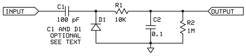
FIGURE 4. The PRM technique is easy to implement and can produce any output wave shape desired. It is limited to low frequencies. As shown, the upper frequency limit is less than 100 Hz.
Capacitor C1 and diode D1 are used here to change a fairly long pulse — or an irregular one — into a very short pulse. The capacitor allows only the edges of the pulse to pass and the diode removes the negative-going pulse. If the output pulse is already very short, these components can be eliminated. Resistor R1 and capacitor C2 form the averaging circuit. Resistor R2 is a bleeder resistor to allow a charge on C1 to dissipate. As shown, the upper frequency limit is under 100 Hz.
PWM has the useful characteristic of being able to act like a charge pump, as well. Depending on how the diode is connected, the output can be a negative voltage (reverse D1) or a voltage above the power supply (anode of D1 connected to Vcc).
Step-Hold
One technique that is rarely used but holds great flexibility is the step-hold method. This requires that the driving signal can be turned off (or three-stated). This is not a problem for modern CMOS microcomputers or ASICs (application specific integrated circuits). It is generally a trivial matter to turn any pin into an input which has a very high impedance (typically >10 megohms). In effect, this disconnects the output pin from the circuit. (Note: The step-hold and the PWM techniques are described in much more detail in the February ‘05 Nuts & Volts issue.)
The basic idea is to output a small pulse to put a charge on a capacitor and then disconnect the driving pin (three-state it) so that the capacitor will hold the value. The output will result in a stepped waveform of any desired shape. This is then filtered to remove the steps with a simple RC filter. Figure 5 shows how this is done.
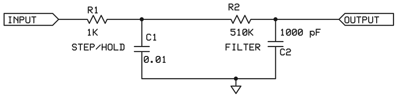
FIGURE 5. The simple step-hold approach looks like a two-pole filter but operates very differently. A small current is briefly applied to C1 via R1 to increase or decrease the voltage on C1. Then the driving signal is turned off and C1 holds the voltage. R2 and C2 filter out the step edges.
(While the circuit looks like a two pole filter, its operation is very different.) Resistor R1 acts as a current limiting resistor so that the capacitor (C1) doesn't charge all the way immediately. Changing R1 changes the step size. The filter is comprised of R2 and C2.
This approach has a number of useful features. The first is that it can be very fast. The maximum frequency is limited by the number of steps you choose and the speed of the microcomputer. If you use a 40 MHz computer chip with 40 steps per wave, you can probably get up to 10,000 Hz for an output signal with tight code.
Additionally, hardware is simple and any waveform shape can be created. Photo 7 is the wave shape taken at the output pin.
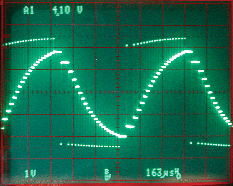
PHOTO 7. The step-hold signal measured at the output pin of the microcomputer (Figure 5). The small pulses pull the voltage on the hold capacitor up and down. The horizontal steps are where the pin is three-stated and show the voltage held on the capacitor.
The stepped wave is created by the very small pulses near Vcc and ground pulling the signal up and down. The filtered 1,000 Hz sine wave is shown in Photo 8. Considering the starting wave shape, this is pretty good.
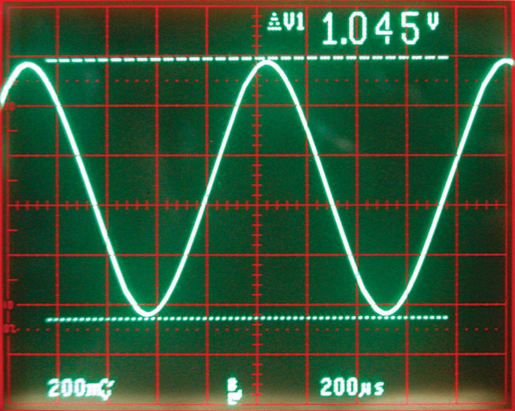
PHOTO 8. After filtering the step-hold wave, the result is a pretty good sine wave.
A problem with this approach is that the size of the steps depends upon the present voltage on the hold capacitor. That is, the steps are not linear. This makes sense when you think about it. A capacitor does not charge in a linear fashion. The rate of voltage increase is less as the charge approaches the charging voltage. A larger current limiting resistor will make the steps more linear but the amplitude of the waveform will be smaller because the steps will be smaller, as well.
However, it is possible to use two different current limiting resistors for the same hold capacitor/filter by using two different outputs. Drive one pin/resistor for big steps and drive the other pin/resistor for small steps. This simplifies the control of the signal.
This approach can also be used for changing the filter capacitors on the fly. Instead of grounding the capacitors, connect them to an output pin. To enable that capacitor, drive the output low (to ground). To disable the capacitor, three-state the pin (make it an input). Considerable variations in filtering (or other circuits) can be accomplished with this technique.
Summary
There are a number of methods for making sine waves and other analog signals from digital values. Some are simple, some are more complicated, some have very limited applications, and others have a wide variety of uses. Having a number of options for your particular application can provide for a better solution. NV