Frequency counters have been around for many years as a standard piece of test equipment in both commercial and hobby labs. They have evolved to remarkable levels of accuracy that are several orders of magnitude higher than most hobbyists could ever use. For example, I borrowed an Agilent 53131 counter to test the design of this project. The 53131 displays up to 10/11 digits of frequency that translates to reading a 10 MHz signal to .001 Hz! Counters of this type use advanced circuits called interpolators that correct the ±1 count tolerance normally stated in spec sheets. My design target for this project was seven digits, so a 10 MHz input signal could be accurate to 1 Hz, and a 10 Hz signal be accurate to .00001 Hz using a one second measurement time (without an interpolator).
Fundamentally, a frequency counter has three main components: a gate signal generator that produces a very accurate gate time interval, usually in the .1 to 10 second range; a counter chain that counts input clock pulses under control of the gate; and a control unit.
For example, if the gate time is set to one second and the input signal is 5 MHz, then the counter chain will accumulate five million input pulses in the one second interval — the exact input frequency.
A binary counter driven by an accurate time reference oscillator (often a 10 MHz oscillator) is usually used to get a precise one second gate interval by opening the gate for exactly 10,000,000 pulses from the reference oscillator.
This configuration works well if the input frequency is equal to or greater than the 10 MHz reference. For example, with a one second gate and an input frequency of 10 MHz, the counter will get 10,000,000 clock pulses for a 7/8 digit accuracy. However, with a 1,000 Hz input, the counter would reach only 1,000. That’s just a three-digit accuracy.
To get high accuracy for lower input frequencies, the counter itself or the user must switch to a period measurement. The roles of the gate counter and input counter are swapped. A period measurement operation (with seven-digit accuracy) is discussed under the software section of this article.
The frequency counter described here has the performance shown in Photo 1.
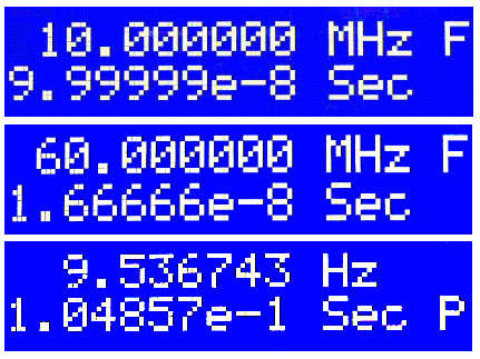
Photo 1.
All measurements use a one second gate time. At the top of Photo 1 is the frequency measured when the input signal is the 10 MHz reference (line 1) and its period (line 2). The ‘F’ indicates that the reading was made by a direct frequency measurement.
For the center display output, I multiplied the 10 MHz by six and made a direct frequency measurement of the 60 MHz signal. The bottom display output is the most interesting.
Here, I set up an external 20-stage binary counter using the 10 MHz as its input. This counter divides the 10 MHz by 2^20 (1,048,576), giving 9.536743 Hz — exactly what the display reads. In this case, a ‘P’ in line 2 indicates that a direct period type measurement was used.
Software in the PIC microcontroller automatically chooses which type measurement (frequency or period) is best.
Figure 1 shows the major components of my frequency counter design.
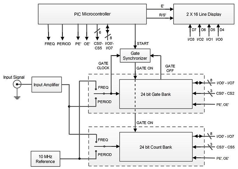
FIGURE 1. Frequency counter block diagram.
It’s based on a 28-pin PIC16F886 and the 74F579 IC — a synchronous eight-bit binary counter with three state outputs that can operate at up to 85 MHz. This version differs from popular designs that use the PIC internal components to do the gating and counting functions. In my design, all critical timing functions are moved from the PIC to the 74F579 counters.
The main building block of the counter is shown in Figure 2.
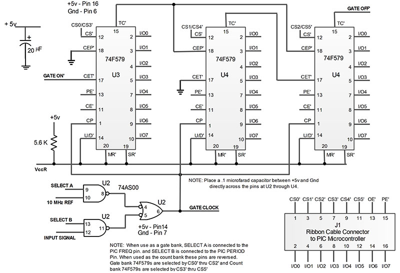
FIGURE 2. Basic counter module for both the gate and count banks.
It has three 74F579 ICs in series to make a 24-bit binary counter bank, and an input switch (74AS00) to allow the PIC to control the input clock source. This building block is used as the gate signal generator and as the input counter.
The 74F579 is designed for bus operation. Its data outputs are tri-state, and are also used as inputs to preset the counter. Operation of the IC uses three control pins: CS’ – Chip Select; PE’ – Parallel (input) Enable; and OE – Output Enable’ (the ‘ indicates logic low active).
The PIC can address each of the 74F579s by setting its CS’ pin to a logic low (0), and setting either PE’ low to preset the chip flip-flops or OE’ low to read the chip flip-flops. So, to preload the counter banks, the PIC sequentially performs a CS’/PE’ pair individually for each of the three 74F579s in each bank. An additional U/D’ pin on the 74F579 controls the counting direction. I set both banks to count up.
The 74F579 is a synchronous counter. To understand what this means, we have to look at how a traditional ‘ripple’ counter works. In a ripple counter, each flip-flop output is the clock input to the next stage so that the delay adds up as the stages add up.
For example, if the delay between the clock input and the change in output state of the flip-flop is five nanoseconds, then since the flip-flop output is the clock input to the next stage, the delay of the second flip-flop is 5 + 5 nanoseconds. This delay ‘ripples’ through the counter.
In a 24-stage counter, the delay at the last stage is 5 x 24, or 120 nanoseconds. Unfortunately, this delay may vary over a two (or three) to one range just due to production variances. A synchronous counter removes the ripple effect by having each stage clocked by the same clock. The synchronous counter operation is necessary for accurate gate timing, but it’s not sufficient. The gate timing must also start and stop on a clock edge.
This is the reason for the gate synchronizer (Figure 3) which uses a 74F74 dual flip-flop.
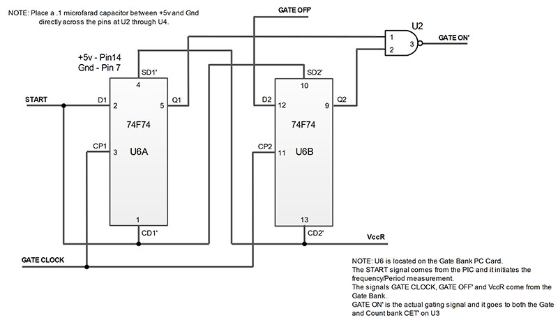
FIGURE 3. Gate synchronizer schematic.
I’ll go through the process of making a simple one second frequency measurement to illustrate the gate operation. Note (as mentioned) that the gate counter is set to count up, so we set it to a value that is minus the desired count.
First, the PIC presets the gate and counter banks. The counter bank is set to zero (effectively a reset operation) and the gate bank is set to minus 10,000,255 (see below). Normally, the START line is logic low, with U6A in the reset state and U6B in the set state.
The PIC starts a frequency reading by first selecting the internal reference as the gate clock and the input signal as the counter input. The PIC then sets START to a one. At the next internal reference clock pulse, U6A sets since U6B is already set. The AND gate enables the CET’ pin on both counter banks, thereby starting the counting.
The TC’ pin of the third stage of the gate counter goes low 256 clock pulses before the gate bank reaches its terminal count. This TC’ is connected to the D input of U6B. On the next gate clock pulse, U6B is reset thus turning off the gate.
I had to preset the gate bank to minus 10,000,255 because the TC’ occurs 256 pulses early and I add one clock pulse for synchronizing, so I add minus 256 plus 1 to the desired gate time. Because the gate bank starts and stops exactly on a clock pulse (because of the gate synchronizer) and the delay through the counter is very low, the gate timing is very accurate. At the end of the gate time, the PIC reads the count bank outputs to get the frequency.
Making a period measurement follows a similar path, except the gate bank and count bank inputs are reversed by U2. The PIC preloads the gate bank with a value equal to minus the number of input signal pulses minus 255.
For example, to count 1,000 signal pulses, the gate bank is loaded with minus 1,255 (minus 1,000 minus 255). Period measurements are a little more complex since we have to pick the number of input signal pulses (the 1,000 in this example).
The accuracy of the measurement depends on how many internal reference clock counts are accumulated in the count bank. If we use the 1,000 signal pulses discussed here and the input signal is 1,000 Hz, then the gate will be open for one second and the count bank will record 10,000,000. This gives us our 7/8 digit accuracy.
However, if the input signal frequency is 100 kHz, the gate will be open for .01 seconds and the count bank will record 100,000 or 5/6 digit accuracy. On the other hand, if the input signal frequency is 10 Hz, the gate will stay open for 100 seconds.
As we’ll see shortly, the software (available in the downloads) solves this problem nicely and will force a gate time of close to one second (or whatever value we want).
Five more components complete the block diagram shown in Figure 1:
- The input signal amplifier.
- The rotary switch input circuit.
- The PIC16F886.
- The display.
- The internal 10 MHz frequency reference.
The input signal amplifier (Figure 4) is used to take a low amplitude input signal with a frequency range of 10 Hz to over 70 MHz and convert it to a TTL voltage level.
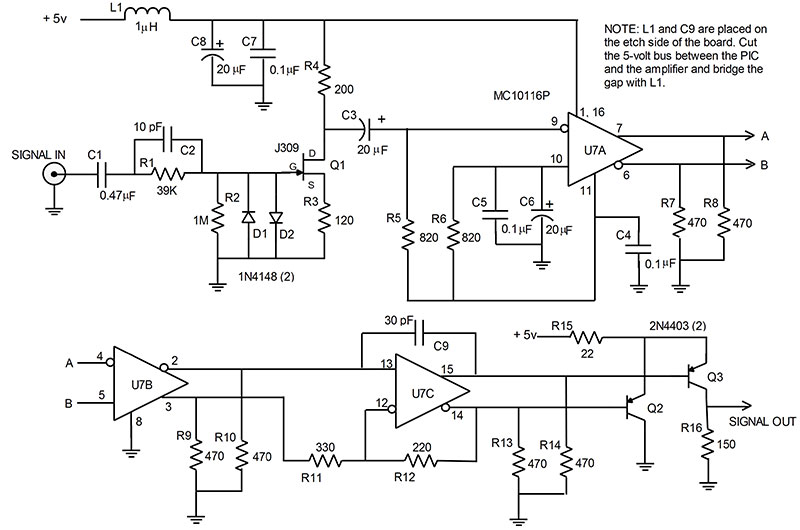
FIGURE 4. Input amplifier schematic.
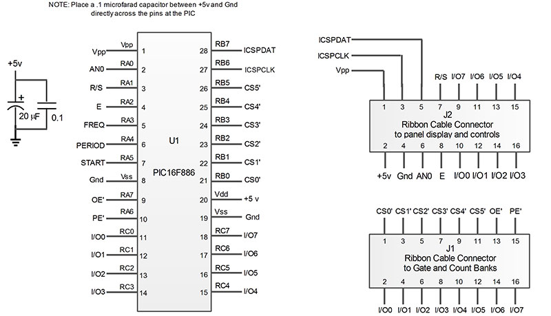
FIGURE 5. PIC schematic.
Every frequency counter has some sort of input amplifier and the Internet is full of designs ranging from simple two-transistor FET amplifiers to multi-component designs often using the popular MC10116 ECL triple line receiver.
The frequency range can be increased to the 300 MHz range, or even higher by using a prescaler. Again, the Internet has many designs for this.
The rotary switch input circuit is simply a four-resistor voltage divider, with the voltage taps connected to the switched terminals of a rotary switch. The switch wiper terminal connects to RA0 on the PIC, and the PIC A/D converter determines the switch position by simply reading the voltage on pin RA0. The software recognizes three switch positions:
- Make high accuracy (7/8 digit) readings (top tap of the switch). These take about 1.3 seconds per reading.
- Make medium accuracy (6/7 digit) readings (center tap). These take about .6 seconds.
- Make continuous (5/6 digit) readings (bottom tap). These take about .1 seconds.
I chose the PIC16F886 (see Figure 6) because it is a cheap popular unit that does the job without overkill.
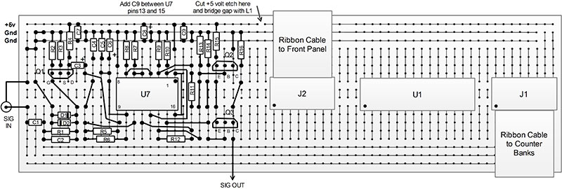
FIGURE 6. PIC assembly.
Since there are no critical timing requirements, the internal 8 MHz oscillator works fine. This PIC also has just enough I/O pins (22 available). If you want to add RS-232 or USB, then try the PICF887. It has plenty of I/O and has USB support.
The display for this project is a 2x16 backlit alphanumeric version. This type of display usually connects with four-bit data bits, but sometimes eight bits are used (these bits are shared with the 74F579 bus) and two control signals (R/S’ and E’).
Fortunately, most compiler products include display drivers so you don’t have to understand the inner workings of the display. (Look ahead in Figure 8 for the front panel components and connectivity.)
The top line is used to display the input frequency in 7/8 digits, plus up to two commas or a decimal point. This is followed by ‘Hz’ or ‘MHz’ and the letter ‘F’ when the gate is on and making a frequency measurement. The second line simultaneously displays the period of the input signal in scientific notation (like 1.2534E-6), followed by ‘Sec’ and a ‘P’ when the gate is on and making a period measurement.
The final item in Figure 1 is the internal frequency reference. The measurement accuracy is totally dependent on the accuracy of the gate time, and thus on the accuracy of the internal frequency reference. The design goal of seven digits is within an oven-controlled crystal oscillator range.
I used a piezo model 2920136 10 MHz oscillator that I bought on eBay for $25. It outputs a TTL square wave and warms up to seven-digit accuracy in about five to 10 minutes. Unlike cesium, rubidium, or GPS references, oven-controlled crystal oscillators have to be calibrated initially. If you don’t have access to a calibration facility, then here is an alternate technique that works.
The National Institute of Standards and Technology‘s (NIST) radio station WWV broadcasts high accuracy signals at several shortwave frequencies, including 10 and 20 MHz. These transmissions contain exact one second time markers, but the carriers themselves are also exact frequencies set by their cesium standards. If you tune a shortwave radio to one of the WWV frequencies at 10 or 20 MHz, you will hear the one second time ticks and some voice messages.
Now, move the radio close to your oscillator and vary the oscillator frequency adjuster until you hear a beat tone as the oscillator frequency approaches and passes through the WWV carrier frequency. As you get very close to the WWV frequency, the beat tone will become inaudible, but you will hear the noise level change in amplitude as the oscillator goes in and out of phase with WWV. It will sound like swoosh ... swoosh ... swoosh.
If you are tuned to the 10 MHz and the swooshing sounds repeat once per second, then the oscillator is accurate within one part in 10,000,000. It’s not difficult to do five or ten times better.
Software
Off-loading the critical frequency counter functions to hardware makes the software control very straightforward. Basically, to make a frequency measurement, the software preloads the count registers to zero; the gate counter to the measurement period (.1 sec, 1 sec); the FREQ bit to one (to set the gate bank input to the 10 MHz reference and the count bank input to the input signal); and finally, the START bit is set to one.
After waiting for the measuring period to end, the software reads the count registers to get the frequency directly for a one second gate or frequency/10 for a .1 second gate. Making a period measurement follows a similar course, except the PERIOD bit is set to connect the gate bank input to the input signal and the count bank input to the 10 MHz reference. The key here is determining what value of input signal pulses to assign to the gate counter.
A HighRes measurement starts with the software making a sample .1 second frequency measurement. The measured frequency is multiplied by 10 to get the actual frequency. If the actual frequency is equal to or greater than 10 MHz, then the software goes on to make a higher accuracy one second frequency measurement.
Otherwise, the software makes a period measurement by setting the gate counter equal to the actual frequency from the .1 second frequency measurement.
This means that the gate time will be close to one second and the count bank will reach close to 10,000,000, giving 7/8 digit accuracy.
Note: We want the gate time to be about one second only to get the desired 7/8 digit accuracy. The frequency will be calculated using the number of 10 MHz pulses accumulated, and the count value preset into the gate counter.
For example, suppose the input frequency is exactly 992.150 Hz and the .1 second reading is 99. We multiply 99 by 10 to get 990, then this value (actually minus 990 minus 255) is set into the gate counter. The gate open time will be 990/992.150, or .9978329 seconds — close enough to the desired one second. The counter bank will end up at 9,978,329. We now calculate the actual frequency as 10,000,000/9,978329 X 990 = 992.150 Hz.
Note that the counter banks are only 24 bits long, giving a total count of 2^24 or a maximum count of 16,777,216. This is fine for the gate counter since its maximum count is about 10,000,000.
However, for a high input frequency, the counter bank could exceed 60,000,000. I get around this by using a counter wrap-around property. When the count equals the maximum, it wraps around and starts again at zero.
So, a 60,000,000 count will actually be 60,000,000 – 3 x 16,777,216 = 9,668,352. This begs the question of how do we know that the counter over-flowed three times. It’s simple. When I make the .1 second measurement, I divide by 1677721 and the number of counter wrap-arounds is the integer result – (integer)6,000,000/167721 = 3.
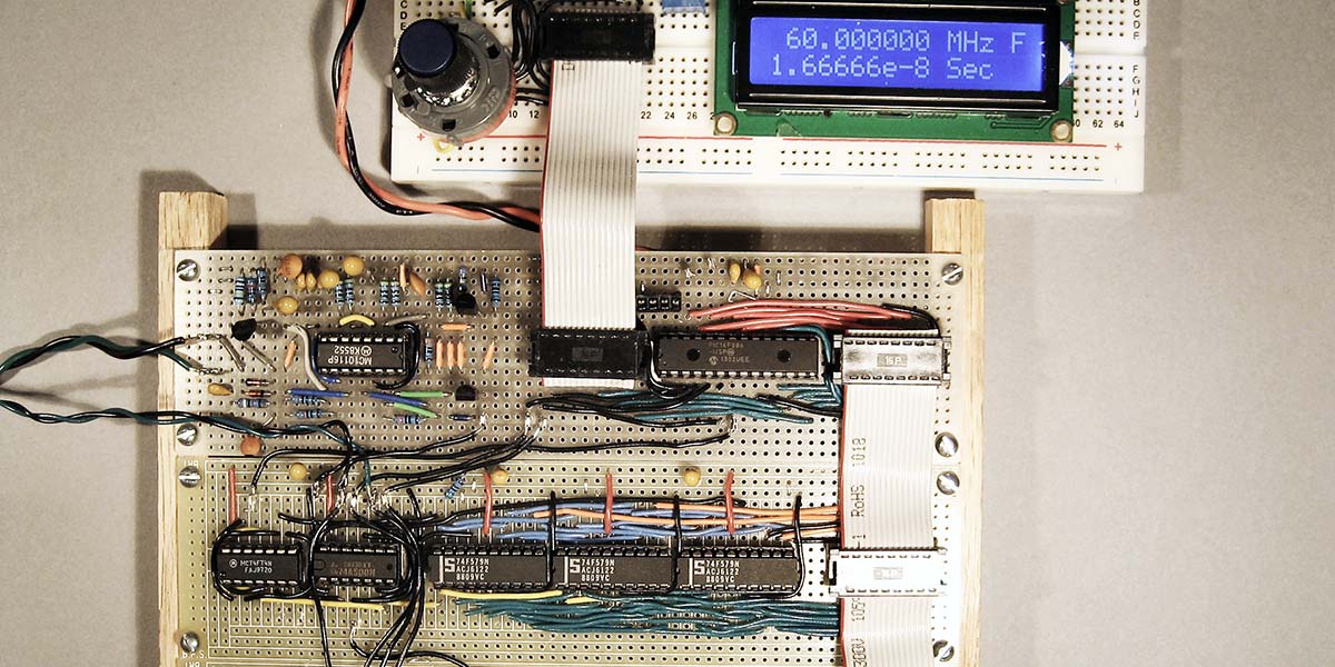
Construction
The unit is built on three solderable prototype PCBs (printed circuit boards; Jameco part 2125034). One board (Figure 6) houses the input amplifier (Figure 4) and the PIC16F886 circuits (Figure 5). (An optional design is to mount the input amplifier in a separate shielded enclosure.)
I isolated the five volt bus for the preamplifier by cutting the five volt etch between the input amplifier and the PIC. I then bridged the cut with a 1 µHenry choke. A second board (Figure 7) contains a counter bank (Figure 2) and the gate synchronizer (Figure 3).
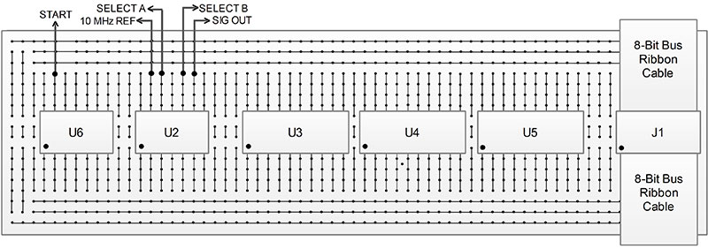
FIGURE 7. Counter bank and synchronizer assembly.
The third board (Figure 5 without U6) contains just a counter bank (Figure 2).
The three boards are connected together via a short 16-conductor ribbon cable that contains the 74F579 data bus and selection and control signals. The microprocessor board also contains a 16-conductor ribbon cable connector for the front panel display and controls. The boards each measure 7 inches x 1-7/8 inches.
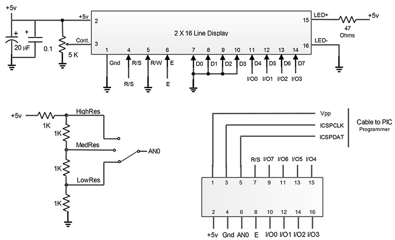
FIGURE 8. Front panel schematic.
When mounted with the long sides adjacent, the total footprint of the counter electronics is about 7 inches by 6 inches. The unit uses about one ampere of five volts for the digital circuits and less than .5 amperes at 24 volts for the piezo oscillator. Most dual 5/24 volt power supplies will work.
Figure 9 shows the main component layout.
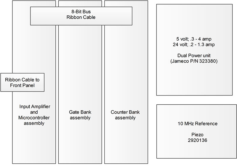
FIGURE 9. Frequency counter assembly.
The footprint is approximately 8 inches x 10-1/5 inches. I purchased all of the parts through either Jameco or eBay. The digital components cost around $30, and the oscillator and power supply cost aboutf $55.
For software development, I chose the mikroC Pro compiler and a cheap PICkit 2 to program the microcontroller. The software design does not use interrupts and can easily be programmed in assembly language or BASIC, as long as floating point arithmetic is available.
Now, go get your “freq” on! NV
Parts List
| QTY |
ITEM |
| 1 |
309 J-FET Transistor |
| 1 |
MC10116P Quad Driver |
| 3 |
2N4403 PNP Transistors |
| 2 |
1N4148 Diodes |
| 6 |
20 µF Tantalum Caps |
| 6 |
0.1 µF Ceramic Caps |
| 1 |
1 µH Choke |
| 1 |
PIC16F886 |
| 6 |
74F579 Counter ICs |
| 2 |
74AS00 Gate ICs |
| 1 |
74F74 Dual FF IC |
| 1 |
Piezo Oscillator Model 2920136 |
| 3 |
BPS BR1 PC Breadboards |
| 5 |
16-pin Ribbon Cable Connectors |
| 1 |
16-conductor Ribbon Cable |
| Various 1/4 watt ±5% metal or carbon film resistors |
Downloads
Frequency Counter Diagrams.zip
All block diagrams and schematics.