My fiancée thought a photo booth would be a fun addition to our wedding reception. She had a table with some props and a cheap camera for people to use in mind, but it gave me an excuse to start a project and build a fully automated portable photo booth. In classic style, an offhand comment about something turned into a few weekends of solder smoke, coffee, and coding.
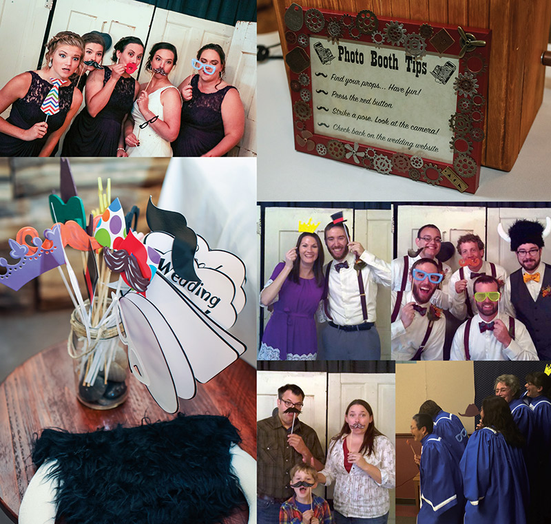
Photo booths are a lot of fun; in fact, most of us can probably remember using them with friends or family and getting those small strips of pictures. It turns out that photo booths were conceptualized in the late 1800s and made a public debut at the World’s Fair in 1889. Shortly after that, they began to show up on streets around the world before becoming a staple of shopping malls and ID card stations. The earliest photo booths used traditional chemical developer techniques that were messy and hazardous, but luckily for me, digital cameras can now fill that role. I wanted to make a digital photo booth that can store and tweet photos for guests.
The requirements I came up with for my project were simple. I needed an easy-to-use photo booth that could be set up by anyone in just a few minutes. It also needed to be portable since I currently live in Pennsylvania and the wedding was in Missouri. The photo booth should take a series of photos so people can try different props and poses. A live preview of the photo was also essential so that nobody ended up headless in our album.
The particular occasion and venue posed a few additional challenges. The venue had very variable lighting and we didn’t want dark outlines as photos, so the photo booth would have to provide its own lighting. It was unclear if Wi-Fi at the venue would be adequate, so photos would have to be stored locally with the option to post to social media, as well.
To fit with the wedding and my general taste, it needed to have a vintage look and feel. The final two constraints were purely practical: It needed to be inexpensive and relatively quick to develop. Anyone who has planned a wedding knows the cost and time that goes into it, and this project could only excuse so much centerpiece duty. The final result (Figure 1) met all of these requirements and was surprisingly easy to build!
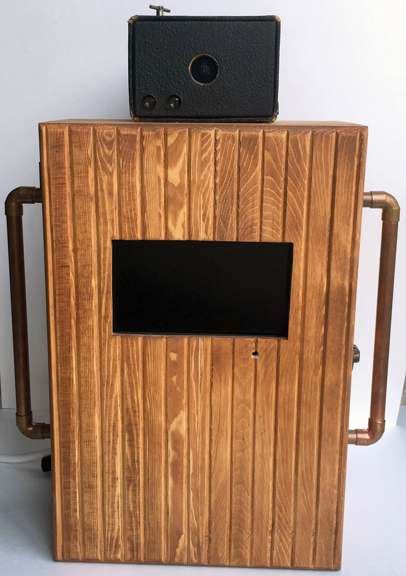
FIGURE 1. This completed photo booth keeps that old-time feel, while making digital photos available to guests just seconds after they are taken.
Hardware Setup
When starting a project like this, it is always a good idea to see what’s in the parts bin already. In my case, I pulled out a Raspberry Pi A+. While the A+ model isn’t good for RAM intensive applications, I didn’t plan on loading the graphical user interface (GUI) for the operating system. It is also a small board and very inexpensive. With the large support community behind it, the Raspberry Pi is also very easy to set up and use.
The first step for me was getting all of the hardware prototyped so that I could start developing the software, and thinking about what kind of enclosure it should all go into. This meant I needed to select a camera and decide on the user interface for the booth.
The initial solution for a camera was going to be an extra Nikon D40X. This — or any other digital single lens reflex (DSLR) camera — would produce very high quality photos with fantastic automatic exposure settings. The problem was that getting a live preview from these cameras is very difficult on most; impossible on some. Even triggering the photo capture was a bit hacky, as on some models I would need to emulate the infrared (IR) remote signal.
A webcam was a cheaper alternative with many of the desirable qualities, but they can be difficult to interface with. It could be done, but the clock was ticking! The optimal solution for me was the Raspberry Pi camera board. This $30 camera plugs directly into the Pi with a ribbon cable that breaks out the camera serial interface (CSI) bus. It will take still photos or video, and it has a really nice set of libraries to control it from the Linux shell or through a Python program.
There is no free lunch, though. The camera is only five megapixels and doesn’t have automatic exposure settings. However, for the size of prints that guests would make and for social media posting, the resolution was plenty. It also has the bonus of smaller file sizes, which comes in handy when dealing with hundreds of photos.
The photo booth also needed a “big red button” that begged to be pressed to start the photo sequence. This needed to be obvious, intuitive, and make that satisfying tactile click. A less obvious button was needed to shut down the photo booth. I certainly didn’t want to connect a keyboard every time, but this button needed to be less obvious and hard to trigger by accident.
As we all know, every good project has to incorporate some blinking lights, and this one is no different. I wanted a flashing light to replicate that of normal cameras when they are put into time delay mode. It also would help draw people’s eyes to look at the camera and not at themselves on the preview screen.
Lighting the photo scene needed to be simple and safe. I considered LED strips, but worried about how to best position them. In the end, I decided on just providing a plug that we could use to switch any lamp we deemed appropriate when setting up. I started building up the transistor/relay circuit to switch the mains power, but found that a product called the “Powerswitch Tail 2” existed. This solved the problem in an opto-isolated and fully enclosed way, and made me feel a lot better about leaving the unit unattended. While my mains wiring would be fine, I didn’t want a curious guest to be able to find AC connections anywhere.
After getting the components I didn’t have, I began to breadboard the design. It is really a very quick and simple circuit. An LED with a current-limiting resistor for the flashing timer light, the two leads to the power switch, and two buttons for trigger and shutdown were all we needed. The general-purpose input/output pins (GPIO) on the Pi are very configurable, so I chose to have the lines held high by the Pi and pulled low by the buttons.
A breakout board like the Pi T-Cobbler makes connecting everything to the right pins a lot more simple and easy to change later, but isn’t necessary. You can choose whatever GPIO pins you wish, but I used those marked in the hook-up diagram shown in Figure 2. That is what the downloadable code (available in the downloads, at the end) will be set up for.
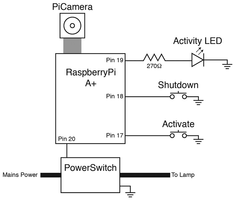
FIGURE 2. Hook-up diagram for the PiBooth. Be sure to keep connections short where possible to reduce the false triggers that the software must fight.
The camera hooks up to a flat-flex connector on the Pi. Be careful that you connect the camera to the correct connector and in the right direction! On the Pi A+, the bare contacts go towards the HDMI connector and the blue strip is towards the USB connector (Figure 3).
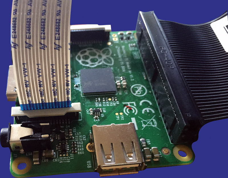
FIGURE 3. The camera connects to the CSI bus through a flat-flex cable. On the model A+, the bare contacts are towards the HDMI connector. Make sure this isn't backwards!
Gently lift the connector bail and insert the cable, then snap the bail back down. A small screwdriver could help if you have large fingers.
For initial prototyping, I hooked the Pi up to my living room television, but it is important to keep testing it with the screen you will use in the end product to catch any resolution issues early. Use a decent quality HDMI cable or you may run into reliability issues.
It is easiest to work with the Pi — at least initially — if it is connected to a keyboard, mouse, and the Internet. I used a small USB hub to break out the single USB port on the A+. Powered hubs are really helpful if you are running into erratic behavior. Wi-Fi modules can consume a decent amount of power and could be the root of the problem. Power is the last thing our machine needs. Again, use a high quality USB cable for durability and because they generally have larger gauge wire than very cheap cables. I used an old Apple iPad charger as my power source. Whatever you use should be able to source about 2A at 5 VDC.
Software
There are a lot of steps to get all the parts in place for the photo booth to work flawlessly and automatically. Hang in there, though; it is worth it!
To get started with your Raspberry Pi, you’ll need to set up the operating system (Raspbian) on an SD card. The easiest way to do this is with a tool called NOOBS (New Out Of the Box Software). You can buy SD cards with NOOBS already installed, or do it yourself. I chose to do it myself on a large (32 GB) SD card to provide lots of photo storage. You can format the SD card with tools already on your computer, or with SD Formatter from the SD Association (www.sdcard.org).
Download the offline and network install version of NOOBS from the raspberrypi.org site (http://downloads.raspberrypi.org/NOOBS_latest) and unzip it. Copy the contents onto your SD card and eject it from your computer. Insert the SD card into your Pi and power up.
You’ll be greeted with a window that allows you to select the OS you wish to install. Installation can take a while, but eventually will complete and an onscreen configuration guide will take you the rest of the way. Be sure to enable the camera during the prompts! You can now log in and load up Raspbian (see the sidebar).
Logging into Your Pi
It’s not uncommon to boot up a new system and not know how to log in. The current distribution of Raspbian has the following default login:
username: pi password: raspberry
It is a good idea to change the default password — especially if you are going to make your project Internet connected. Just type “passwd” at the terminal prompt and follow the instructions. You can even create a new user, but be sure to modify the setup instructions to use that account instead of the Pi account.
Before continuing, it’s a good idea to update the software on your Pi since the NOOBS distribution and packages could be a little dated. Make sure you’ve set up the network connection and at a terminal prompt, type “sudo apt-get update,” then “sudo apt-get upgrade.” Again, this took a while for me to complete.
While we have the Pi connected to the Web, we’ll download the photo booth software and dependencies, as well. We need the Python package manager (Pip) to install the Twitter client, so run “sudo apt-get install python-pip.” Now, install the Python Twitter package, Twython: “pip install twython.” Finally, navigate to the home directory (“cd ~”) and clone the software repository by typing “git clone https://github.com/jrleeman/PiBooth.git.” With that, you have installed all the software you need.
Now, we need to set up Twitter authentication. If you don’t want to use Twitter, you can skip this with no consequence. Sign into your Twitter account and go to https://dev.twitter.com. At the bottom of the page, click “Manage Your Apps.” Here, you can create a new app.
Enter a name for the photo booth and create the application. In the “Keys and Access Tokens” tab, you’ll find the Consumer Keys. Below the Consumer Keys you can generate the Access Token. Copy and paste the Consumer Key, Consumer Secret, Access Token, and Access Token Secret into their respective places in the photobooth.py file you downloaded from GitHub. While there, change the “tweet_photos = False” to True. You can even set up random Tweet captions for your photos (refer to the sidebar).
Randomly Tweeting Text
Initially, I had the photo booth tweeting the photos with some default text that is stored in the tweet_text variable. You can still do that, but if you put a text file in the PiBooth directory that has different tweets on each line and set tweet_text to that filename, the photo booth will randomly select a tweet from that file and make your Twitter stream a little more interesting. Below are some examples of the tweets that we used. You can follow my photo booth’s adventures by following @Pi_Booth on Twitter.
These people really pushed my buttons.
... and all I got was these photo booth pictures.
Awww.
Hey, I just met you, this is crazy.
I wasn't lucky, I deserved it.
I had fun once, it was horrible.
Smile 😊
Hi there!
OMG that's so cute!
Collect moments, not things.
These people ...
Best selfie ever!
Frankly my dear, I don't Instagram.
If you choose to tweet, you’ll also need to set up the network connection. I opened the GUI for the operating system by typing “startx” at the command prompt, set up the network, and then rebooted.
If you want to understand how the Python code does everything, you should dig around and play with it. The pygame module is used to do text overlays, show a countdown to the photos, play a shutter sound when the photo is taken, and to handle key press events. I didn’t expect to change the contrast and brightness settings often, but didn’t want them hard-coded. They are tied to the arrow keys with pygame. The text overlays could have been done with the camera module, but this was the best looking way to do it.
The time module is used to control timing on execution and to provide unique names for all of the photos based on the date and time they were snapped. (Time stamps are a great way to ensure unique file names — as long as your clock is right!) Raspberry Pi provides the GPIO library that lets us toggle and read pins for the buttons and LEDs. The Pi camera module controls the camera.
We start the live preview and do the photo captures with it. The sys and OS modules handle housekeeping tasks like cleanly exiting the program, shutting down the Pi, and working with the file system. To make things a little more fun, we use the Twython module to tweet the photos, and the random module to let us select a random set of Tweet text to go with the photos.
To start your photo booth, just run “sudo python photobooth.py” at the terminal. After a few seconds, your camera preview will appear. If it’s flipped, just exit the program (ESC key or Control C) and adjust the hflip or vflip settings in the code. Now, press the trigger button. The photo booth will turn on the power switch, do the countdown, take your photo, repeat three times, then turn the power switch off.
Make some faces and have fun, then exit the program. Your photos will be in the /home/pi/photobooth_photos directory and should be posted on Twitter if you have that enabled. If something went wrong, the error messages will point you to what part of the setup is incomplete.
Once you’re happy with how things are working, we need to set up the Pi to start up the photo booth program by default. We don’t want to connect a keyboard at every startup. Remember that easy setup was a requirement. We need the Pi to automatically log in and then start the script.
At a terminal, open the inittab file with your favorite editor (i.e., “sudo nano /etc/inittab”). Find the line that reads “1:2345:respawn:/sbin/getty 115200 tty1” and put a “#” at the beginning of the line to comment it out. Directly under it, type “1:2345:respawn:/bin/login -f pi tty1 </dev/tty1 >/dev/tty1 2>&1.” Press Control+o to save the changes and Control+x to close the editor.
Now, we’ll tell the Pi to run our program in the shell profile. Open the profile in an editor (i.e., “sudo nano /etc/profile”) and at the bottom of the file, add “sudo python /home/pi/PiBooth/photobooth.py.” Reboot with “sudo reboot now” and you should be all set.
Enclosure
Now comes the real fun: designing your enclosure. You can get very creative here and build something to fit your exact vision. For me, I wanted a steampunk look that was durable. This meant wood, copper, antiques, and gears. I also couldn’t build the box from scratch since I didn’t have a table saw on hand.
Hobby stores and antique shops are a good place to go for inspiration and parts. I found a wooden cabinet that was unfinished for the main part of the system and a small metal box for the big red button. The boxes cost about $20. At an antique shop, my fiancée found an antique Kodak “Brownie” camera for $15. I repurposed the camera and brought it about 100 years forward in time with a digital upgrade.
I cut out a hole for the monitor using a jigsaw and drilled a hole for the IR receiver on the TV. The monitor was mounted with plumber’s tape, double-stick tape, and M4 screws (Figure 4). I stuck the remote inside the cabinet with some Velcro™ so it didn’t find its way into oblivion. All the cables were secured with hot glue. The front panel was now complete.
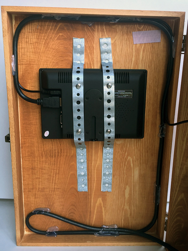
FIGURE 4. The 7" monitor can be securely mounted with plumber's tape, some metric screws, and heavy duty double-sided tape. Notice the cable routing and Velcro for the TV remote.
The Pi camera board was glued into the front part of the Brownie camera. I placed some electrical tape over the LED and used some black felt to conceal the green PCB (printed circuit board) from view. Then, carefully, I cut a slot in the paperboard part of the camera and threaded the flat-flex cable through. I bought a longer flat-flex cable, but this depends on your setup.
While the camera was apart, I removed some extra metal parts that were in the way, and also took out a glass plate from the viewfinder. That’s where my flashing LED was set with some glue. I used the jigsaw again to cut a slot in the top of my wooden box for the flat-flex. I then drilled two holes through the box and camera case to secure it down with some 6-32 hardware.
I mounted all of the electronics to an acrylic sheet using 4-40 hardware, standoffs, and hot glue. I then mounted that entire assembly in the box with the same hardware and standoffs (Figure 5). This backplane construction makes for easy removal/servicing and fewer holes in the box. Finally, I drilled a large hole for the mains plug and power switch plug to exit through, and concealed the space with more felt.
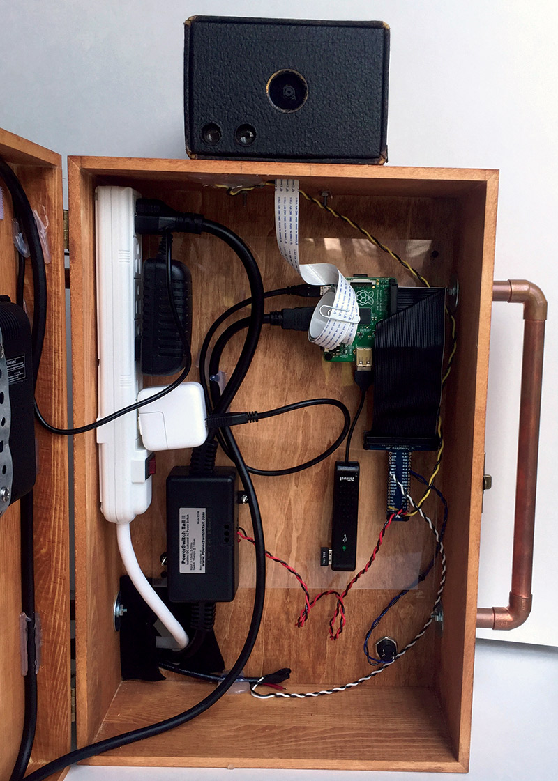
FIGURE 5. Careful removal of a viewfinder glass allowed me to mount an LED inside the camera and use the existing optics as an updated light pipe.
To dress things up a little more, I made some copper pipe handles out of 1/2” tubing and added a frame with instructions on how to use the photo booth. The frame and box were decorated with some gears and watch parts that are sold at hobby stores and on eBay.
The big red button fit very nicely in the diamond plate box I found (Figure 6).
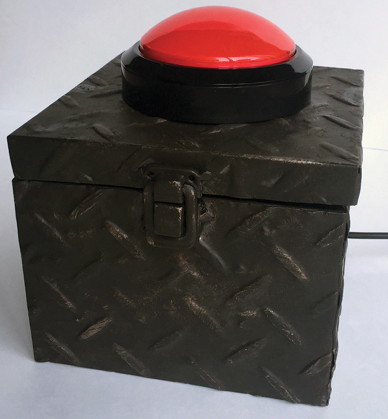
FIGURE 6. All electronics were mounted on an acrylic sheet as a backplane. Equipment with no mounting holes was hot glued or attached with double-stick tape. A cordless drill made quick work of the wiring harnesses.
Step drills are the best tool for drilling large holes in panels, but be careful and take your time. I drilled a small hole in the corner of the box for the lead wire and fit it with a grommet. I used rotor wire since it was on hand, had three conductors, and was inexpensive. In the end, I didn’t power the light in the button because it wasn’t all that bright or well diffused.
Depending on your box, you may find it helpful to add some weight to keep it from skittering all around the table as people push it. I also used a rather overkill waterproof three-pin connector to let me separate the button and main unit for transport.
Closing Notes
You can fine-tune your photos by using the arrow keys to adjust the contrast and brightness settings for your venue. The up/down arrow keys control brightness and the left/right keys control contrast. These settings are reset with each reboot to the defaults that seem to work best in a normally lit room.
This photo booth provided our guests with seemingly endless entertainment at the reception, and will likely be a hit at your gathering as well. If you wanted to make this a real booth with a curtain and a bigger screen, it is very scalable.
Other fun additions could include printing the photos for guests or adding an email option. The possibilities are endless. Your prop selection can grow and expand as you see what people have fun with, but we found the more over the top, the better. Happy photo taking! NV
Useful Links
SD Formatter
www.sdcard.org/downloads/formatter_4NOOBS
Download
http://downloads.raspberrypi.org/NOOBS_latestGitHub
Repository for PiBooth
https://github.com/jrleeman/PiBoothPiBooth's
Twitter — The Art of Command Line
https://github.com/jlevy/the-art-of-command-line
Parts List
Downloads
What’s in the ZIP?
Associated files and extras for building the RaspPi photo booth.