I like building things within my budget and beyond my imagination. If you are at that same threshold, this article is for you. There are always certain aspects of a project that you don’t know what you don’t know. We must confront that truth when building new complex projects.
If building a submarine interests you, I have here a great project that will give you some good ideas and many techniques to learn. If you have a robotics project or an all-terrain vehicle or boat, follow along as I have some great building secrets to share with you, too.
Background
At the time I considered this project, I was working for the Disney Company as a model builder for the movies “Con-Air” and “Deep Rising.” I was hopeful that my project might succeed with a little help from the Disney model building geniuses. I would learn and deal with devices and concepts unknown to me at the time of initial commitment, and this developing knowledge would make my Alfa submarine project a reality. Though not an engineer — but with some experience in the Army Engineer Corps as a heavy equipment repairman — I eventually evolved as one, with this submarine project as a measure of my skills.
I didn’t know very much (in fact, I knew almost nothing) about air pressure control, compressed air holding tanks, manometers, Mapp gas, silver soldering copper, casting in urethane, casting tin bismuth in a silicon rubber mold at temperature, making complex silicon rubber molds or making prototypes of cardboard and wood before committing to metal fabrication; anodizing, using potting compounds, making various tools to make parts, the importance of wire gauge and of amperage, and many other issues regarding this build. Thus would begin a 10 year electro-mechanical nautical engineering project.
The construction and design of the operating system were to come from some general ideas mostly from my imagination and some well thought out common sense engineering. I didn’t know at that time, but I was going to stretch my creative model building brain cells to their maximum. My motivating inspiration was to utilize an on-board air compressor to fill a pressure tank to expel air to blow ballast.
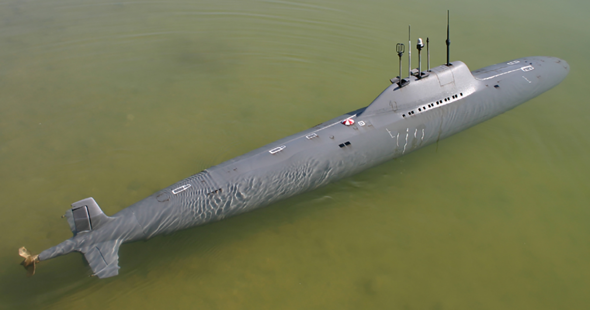
I built a 22 inch long model R/C sub sold by a company in Germany and I was very intrigued by the nature of a radio-controlled submarine. I succeeded with that model building endeavor and decided to take on a larger, more ambitious sub building project. I thus attempted to build part-for-part a five foot radio-controlled Russian Alfa class submarine. I designed and built the entire operating system.
Keeping The Water Out
Essential to the submarine — and contradictory to its nature — is to keep all interiors of the electrical/mechanical compartments dry.
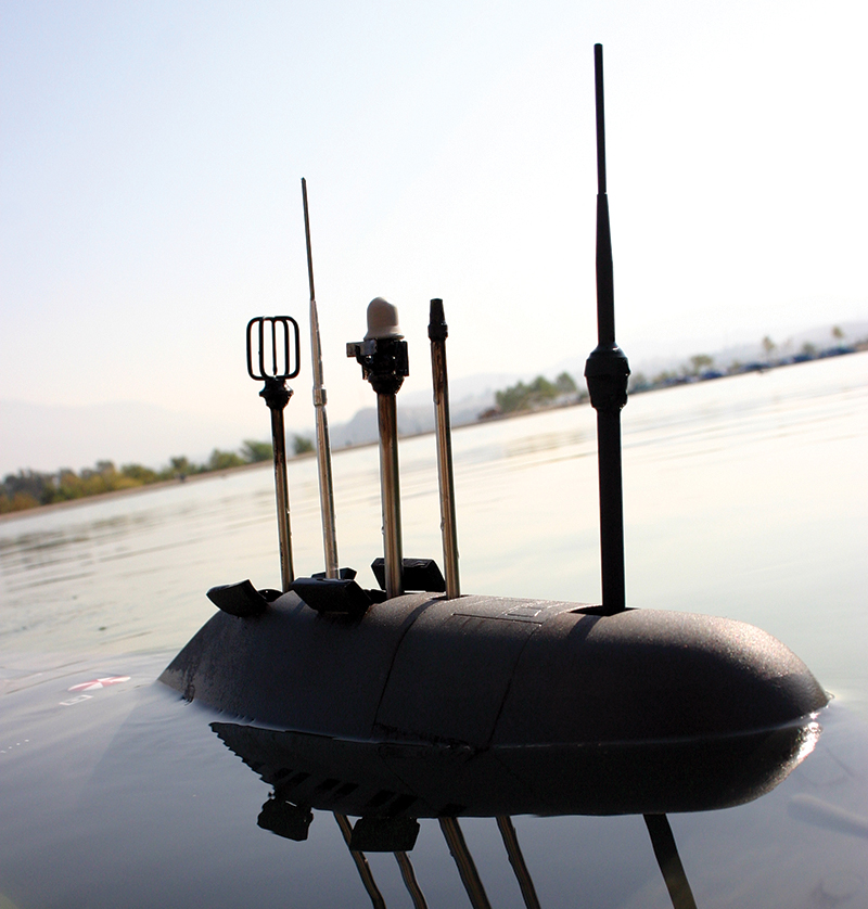
The Alfa hull was to include five watertight capsules enclosed in four inch and seven inch diameter tubing. The hull included rudders and housings, propeller and shaft, alignment pins, rudder yokes, antenna array, clips to hold the top hull half to the lower hull half, the 12 volt battery, and the motor reversing relay switch. The first section is the rear watertight compartment housing the rudder servos and the 12 volt Pittman motor.
The second watertight compartment is the electrical heart of the ship containing the incoming power, as well as the speed control, R/C receiver, automatic pitch control, motor reversing mini servo, air compressor on-off micro switch, and ballast blow micro switch and servo.
The third watertight compartment (made up of a seven inch diameter PVC pipe) contains the air compressor, two Clippard valves for ballast blow and incoming air, and the servo to open the ballast tank air evacuation hole. The fourth area is the ballast tank and compressed air holding tank located within the ballast tank. The final capsule contains the motor reversing relay.
These capsules all have end-caps with a rubber sealing gasket at each end.
Plans And Plugs
I liked the simple exterior design of the Russian Alfa Class sub and I found I could buy plans for it through a Canadian company called Deep Sea Designs. My concern was building an operating system more than building up a complex sub with detailed deck work, deck cannons, and railings.
The plans arrived and needed some verification as some Department of Defense (DoD ) photos of the Alfa exterior didn’t match what the plans showed. The plans have only surface details and the sections on them. The interior was totally engineered by me.
There weren’t many details available of the Alfa then, and there still aren’t now. The DoD released some photos of the Alfa at sea and that’s about it. I found that the sail (conning tower) was too short on the blueprints, so I lengthened it to match the DoD photos.
The hull buildup is the same as building an airplane fuselage or planking a wooden ship model. Balsawood and plywood are the materials of choice for the hull plug (the plug is the solid hull from which the mold is made).
The plug is discarded after use and provides the stepping off point for surface details such as the hatches, torpedo tubes, vent holes, and doors.
I made the conning tower separately and attached it later to the main plug. All the hatches, torpedo tubes, and vent holes had to be located, as well as the ship centerline for later casting in two parts. After I trimmed and sanded the balsa plug, I coated it with epoxy and engraved the hatch and vent hole locations with a carbide tipped tool. I made templates where necessary and located 75+ locations top and bottom.
The completed finished hull plug is shown with me holding it in Photo 1.
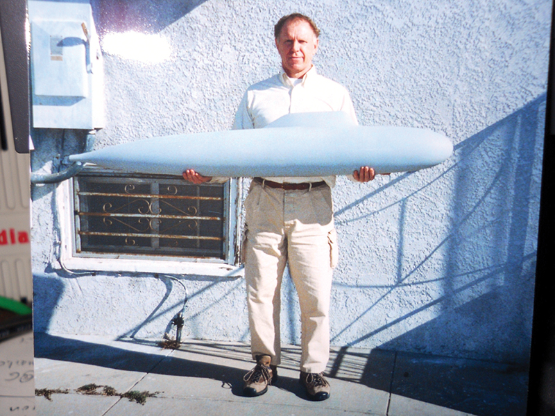
PHOTO 1.
Photo 2 shows the finished hull plug with a profile of the blueprint shown in the background.
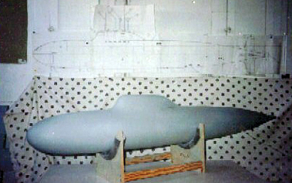
PHOTO 2.
I made a two-part fiberglass/epoxy mold and cast the two-part hull shown finished in Photo 3.
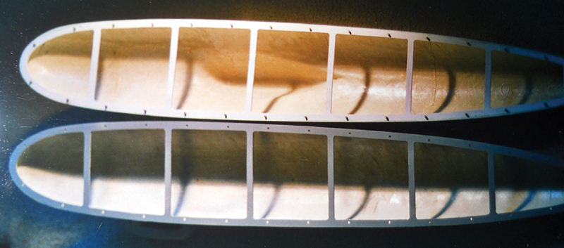
PHOTO 3.
The hull upper and lower halves were cast in fiberglass cloth impregnated with epoxy resin. Photo 4 shows a close-up of the stern alignment pins.
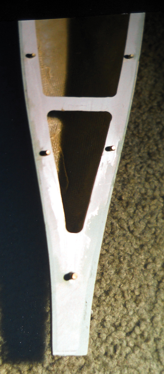
PHOTO 4.
This hull building procedure can be applied to any original model robotic device one may wish to make. It also remains the standard procedure to follow. Epoxy mold building and casting is not easy, and trying it first on a small scale is advisable. Epoxy has various setup times so using something one is familiar with will save time and product. Remember, I selected a very simple two-part hull to cast. A more complicated shape would require a more complex plug and mold; experience is the key to success.
Making Prototypes
Other hull components like rudder brackets, rudders, hatches, and the propeller were all wooden prototypes cast in hard urethane plastic “siltool A/B” produced by Silpak, Inc., in Pomona, CA. These were cast from simple two-piece molds providing good practice for the more difficult mold used for the propeller. A great product to make rubber molds from is the crazy sounding “OOMOO.” Google this name, and there it is. The OOMOO producers have removed the air from the two-part OOMOO, thus creating an air bubble free mold. I recommend this, though I found out about it only recently. I used a Silpak two-part silicon rubber mold material that also worked fine, but did produce bubbles under flat parts. I have no vacuum chamber to extract air. Photo 5 shows my mold setup.
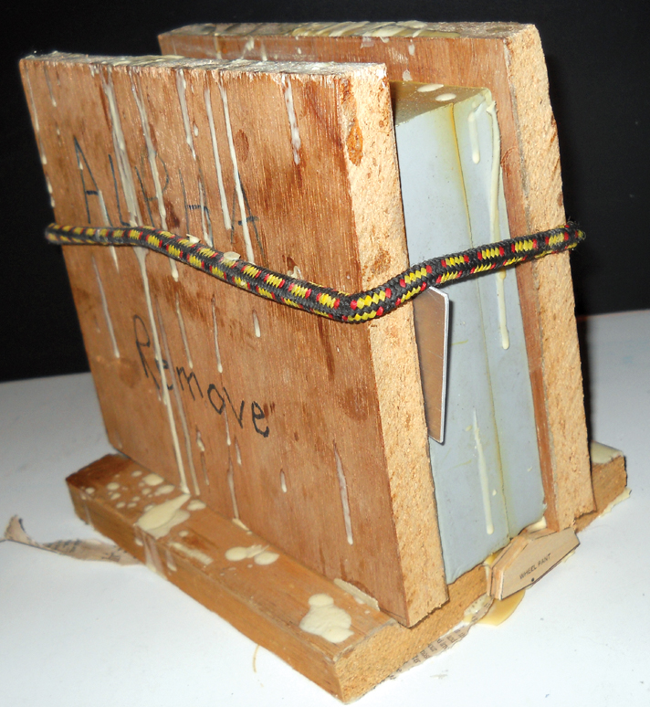
PHOTO 5.
I used this wooden base and support style on three of my molds and I liked the idea. The mold is stabilized and easy to work with. The mold in Photo 6 shows my early solution to casting the rudder extensions and the creeper propellers at the same time.
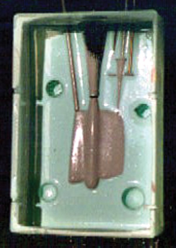
PHOTO 6.
The creeper propeller acts as the air/gas escape sprue and casts the creeper propeller at the same time. Later, I cast the creeper propeller separately in tin bismuth — a fairly low melting point alloy. The tin bismuth could be poured directly into the silicon mold while hot, without damage to the mold. I couldn’t believe this until I tried it. White metal works the same.
It Gets Complicated
Here comes some real mold building fun. I had planned to have the propeller made at a machine shop out of brass, but I found the cost rather prohibitive. Thus, I decided to make the propeller myself.
When I began this project, I had some uncertainty regarding the propeller. I found no actual photos of it. I went strictly by Greg’s blueprints. I was almost convinced that the propeller was actually a scimitar type like the Akula submarine and not the five-bladed one on the drawing. I decided to go with the five-blade design which I found out later to be correct.
Photo 7 shows my propeller buildup sequence.
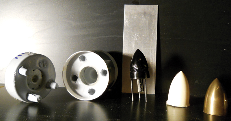
PHOTO 7.
I was nervous about the propeller due to its complexity because of the blade’s pitch. I concluded that I would cast the propeller in hard urethane and cast a threaded aluminum standoff into it for added prop shaft strength. The lightweight hard urethane proved a good product for the propeller, as a heavy brass propeller would have added unnecessary drag and would have overheated the motor. The sequence of hubs in Photo 7 shows the original brass hub on the right which I turned on the lathe to the scale on the blueprint. I made a silicon rubber mold of this simple hub by immersing it in the silicon to the base of the hub, then casting it in hard urethane plastic.
After the urethane hub was cast, I made the black hub with the grooves at points where the propeller blades were later attached. I then made the simple two-piece mold pictured to the left. After casting the black urethane hub with grooves, I mounted this hub in a jig as shown in Photos 8 and 9.
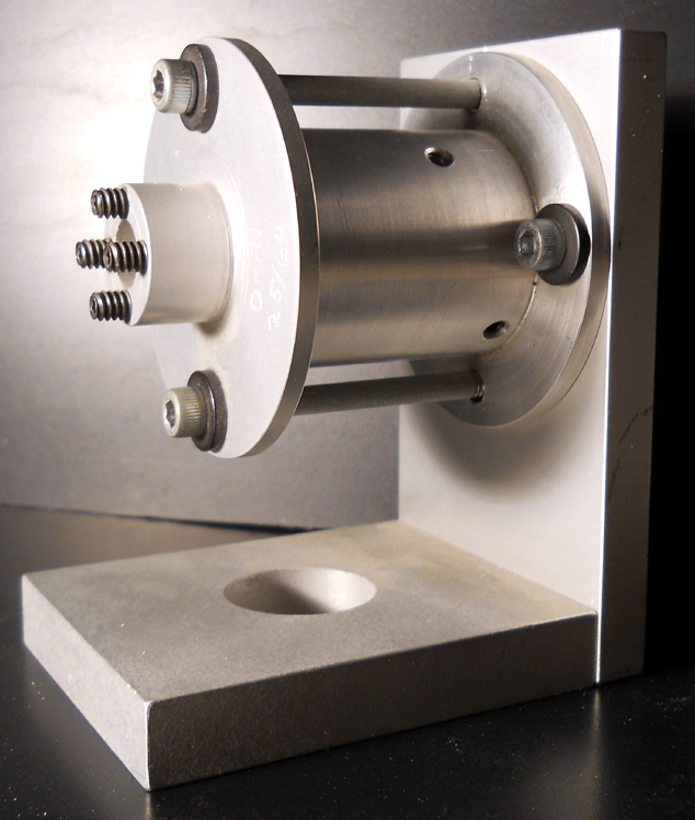
PHOTO 8.
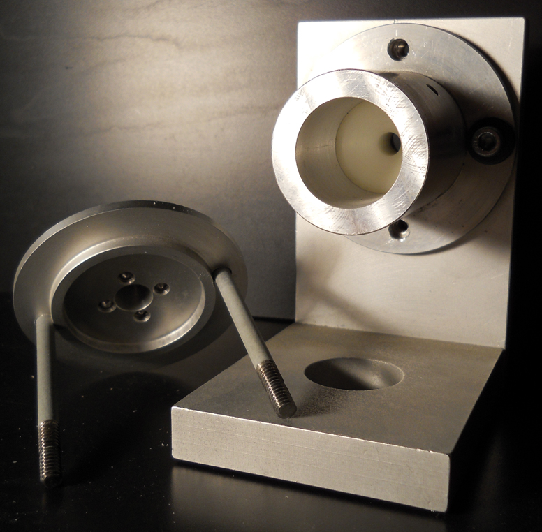
PHOTO 9.
This special-built jig allows for the hub to be held in place while a 25/64 hole is drilled into it to press-fit a threaded aluminum standoff in place. The standoff insert is for latter alignment, so the hub can be bolted to the propeller blade attachment jig.
What exactly is pressfitting?
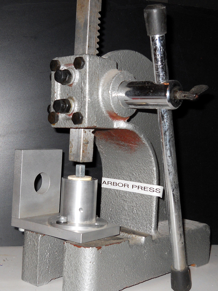
Pressfiting is pressing an item (standoff) into another part (propeller hub) with an arbor press. The 25/64” hole in the hub is slightly smaller than the six-sided threaded standoff and needs no glue to hold it in place.
I made a single propeller blade out of wood, then made five castings of it in hard urethane to be attached to the prepared hub. The prepared propeller hub was attached to a simple jig where I glued the blades to the hub one at a time. I used super glue and sanded and filled the blades as needed to create a good propeller for casting. This jig setup is shown in Photo 10.
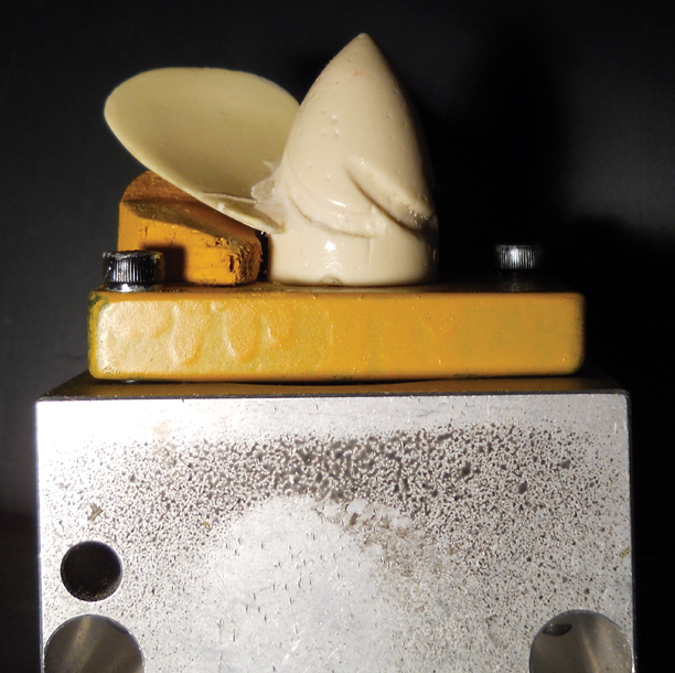
PHOTO 10.
Once the propeller was perfected, I prepared it for the making of the silicon mold. I estimated where I would need venting sprews and glued plastic dowels along the rear edges of the propeller to the height I thought the top of the silicon would be. Herein were three unique challenges.
One challenge was how to cast this propeller in a two-piece mold. The second challenge was how to align the standoff in such a way that I could cast it into the propeller at pouring time. Remember that when the propeller is cast, the negative space is what remains in the mold to receive the liquid urethane. At the same time, the aluminum standoff must be suspended in its position within the empty space at the proper height and centered.
Photo 11 shows how this is done.
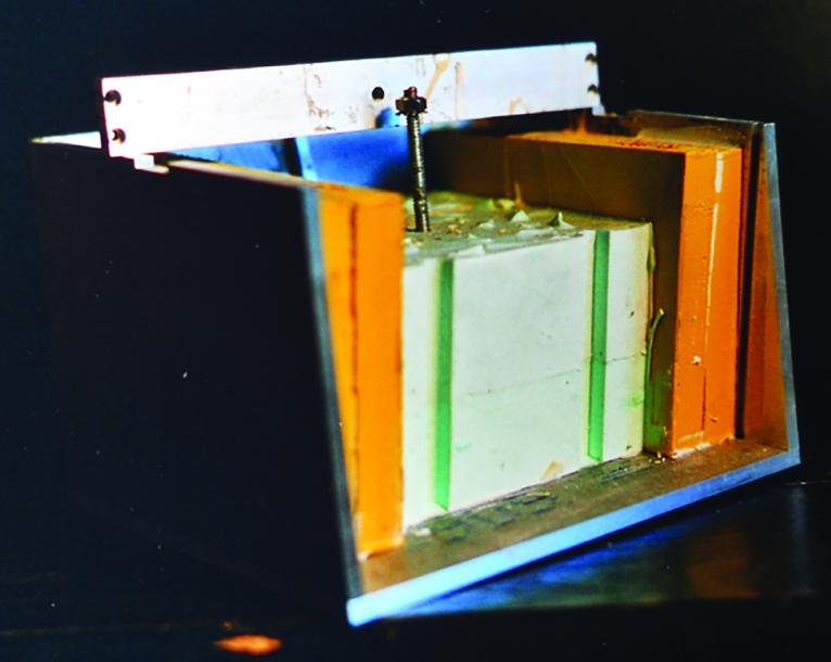
PHOTO 11.
This photo shows the completed mold in its casting box. The aluminum bar across the top will hold the threaded rod pictured with its bolt. The threaded rod penetrates the mold at the center of the empty propeller location with the aluminum standoff attached to it. I can just unscrew it when the propeller is cast. Photo 12 shows the open mold with the cast propeller in its location.
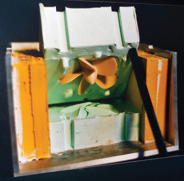
PHOTO 12.
The third and more difficult challenge was casting this unusual propeller shape with its undercut blades in a two-piece mold. Look carefully and you can see how I solved this issue. With the prototype propeller set in and hardened into the silicon in the lower mold half, I tilted the completed lower half of the mold five separate times and filled in the undercut spaces. I filled in the spaces under each propeller blade individually, thereby eliminating the empty space beneath them. Because of the flexible nature of the silicon mold, I could make this work without needing to be really precise. I searched for perfection in the centering of the standoff in the propeller, but there were times I failed to reach these high standards. I cast multiple propellers till I got a really good one. Photo 13 shows the standoff cast into a sample propeller.
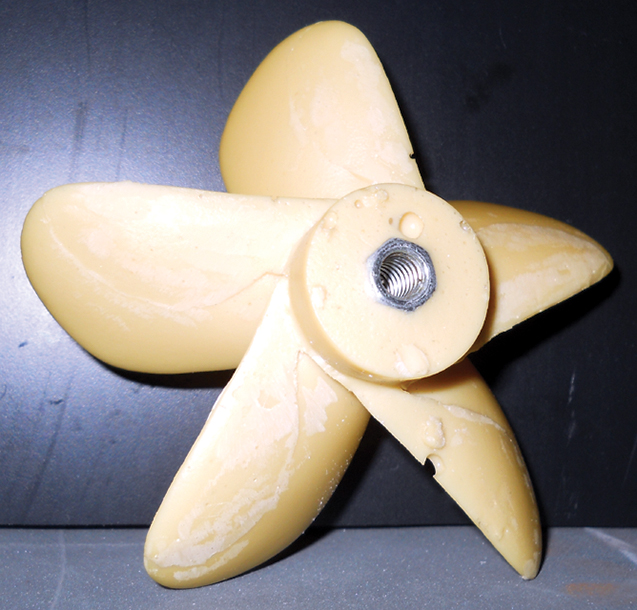
PHOTO 13.
I’ve included a photo of the mold for the rudder housing in Photo 14, so you can see how the air escape risers are included to prevent air bubbles from forming at the ends of parts which then leave un-cast areas in the part.
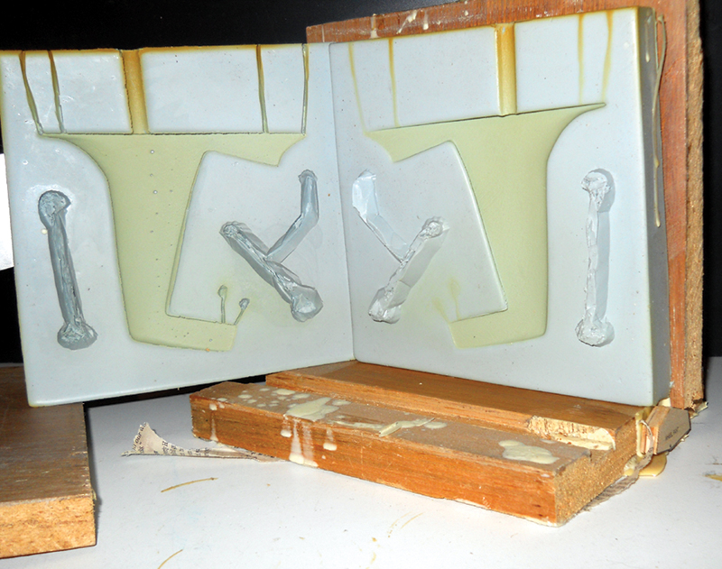
PHOTO 14.
Hatches, rudders, and the bald head radar unit in the antenna array were cast this way. Rudders and rudder supports can be seen in Photo 15.
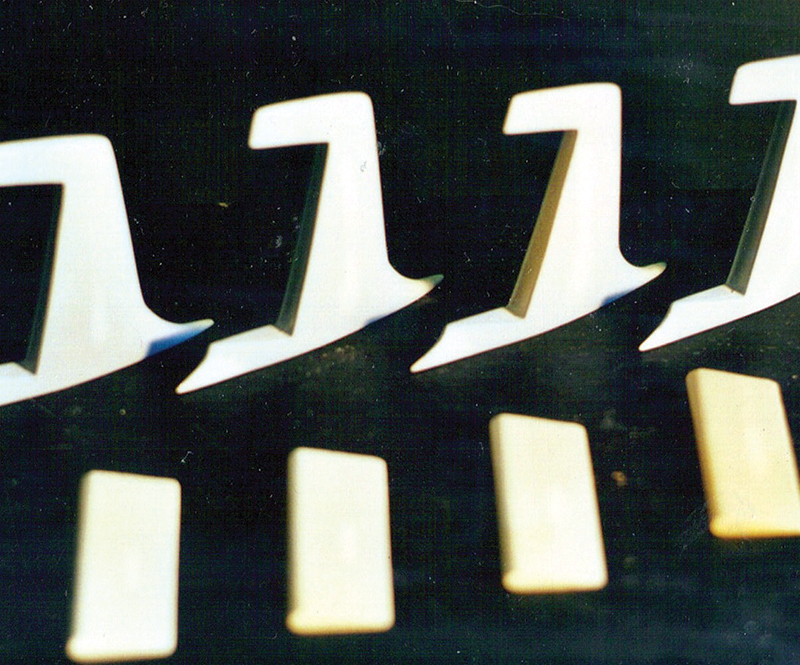
PHOTO 15.
Mold-making techniques improve with practice and are a useful skill to know, no matter what form of project one pursues.
The next part in this series will begin with finishing the stern of the ship by installing the rudder yokes, rudder housing, and rudders. Part 2 will also explain and show the actual assembly of the components into the overall body of the sub itself. Part 3 will cover common sense approaches to maximizing your radio control system and dealing with electrical issues. NV