Please keep in mind that we are several Workshops into the discussion of an Arduino Fritzing Prototype to Production project using an Arduino alarm clock as an example. Arduino is a novice-friendly microcontroller development system; Frtizing is a novice-friendly electronic design system — breadboard to schematic to printed circuit board (PCB). Using these together provides a complete novice-friendly path from that 'AH HA!' moment when the concept leaps into your mind, to the final physical realization of the concept.
We are using an alarm clock design as a substitute for 'AH HA!' since this concept covers many aspects of general microcontroller systems. We are learning how to write the software both for the PC and the Arduino for our alarm clock, and we are learning how to make the hardware first on an Arduino shield, and then — using Fritzing — we are learning to design our own PCBs for the project.
The end goal will be a single PCB of our own design (using Fritzing) that incorporates the Arduino circuits (without requiring an Arduino) along with the DS1307 RTC (real time clock) alarm clock circuits. This board will work with our PC and Arduino code to provide not only a working alarm clock — but more important — the knowledge needed to log data and to control devices at known intervals — the basis for most embedded systems projects.
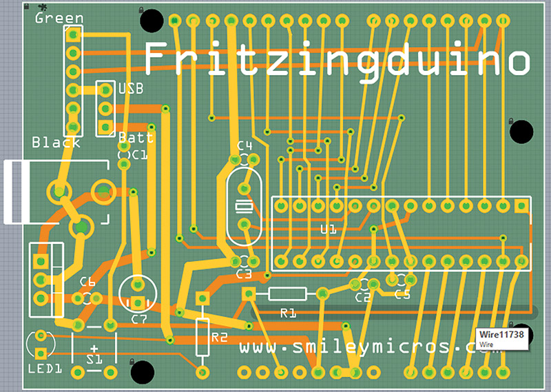
FIGURE 1. Fritzingduino PCB layout.
In our last episode, we finished the Process_Alarms module in the Arduino alarm clock software and looked in detail at the accuracy of the DS1307 RTC. In this episode, we are going to split the article between software and hardware. We will first see how to make our RTC more accurate, and then we will jump back into the hardware where we will take all this stuff we've been learning about using Fritzing for Arduino shield designs and figure out how to incorporate both the Arduino core circuits and the shield circuits into a single design using a single PCB — in effect, we will learn how to roll our own Arduino. (Whew!)
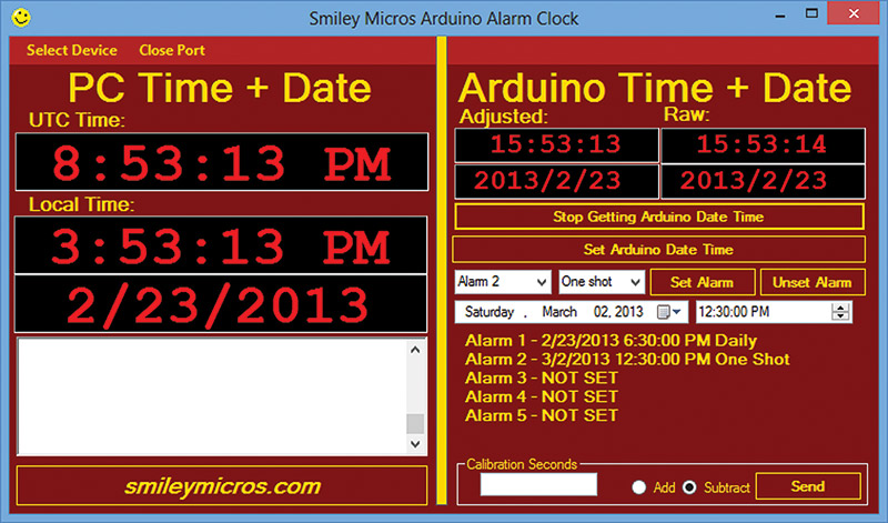
FIGURE 2. Arduino alarm clock.
Making the DS1307 RTC More Accurate
Last time, we began looking at the accuracy of the DS1307 RTC and ways to calibrate it so that it will be more accurate. We learned that it can be off by up to + or - 1.7 seconds per day. That's almost 12 seconds per week, or 10-1/2 minutes per year. Does this matter? Well, if you are plugging your AAC (Arduino Alarm Clock) into a PC every few days and recalibrating it, then probably not. After all, what’s a few seconds among friends? However, if you are going to set this thing as some sort of data logger that goes unattended for months, then yes it probably will matter. It really depends on the application.
Last time, I claimed that I thought I could make this thing as accurate as the more expensive and accurate DS3234 that has a built-in temperature compensated crystal. The modest folks at SparkFun call their breakout board for this chip "DeadOn RTC - DS3234." So, we can take it that the rated ± two minutes per year is DeadOn. Will ours do this? I think so, but I'll have to run one for a few months to get an idea. So maybe, maybe not. As they say, time will tell.
Also last time, we approached calibration by watching the RTC and the PC for a week or so to see how far off the clock drifted. We then derived the number of seconds that passed for each second that the RTC drifted, and whether that drift was + or -. We called these seconds calSeconds and manually entered them into the 'calibration seconds' box in the PCAAC application.
My first inclination was to calibrate by having the RTC adjusted each time it got off by a second. Unfortunately, I kept running into walls doing that, mostly due to me over-thinking the whole thing. Finally, after wasting too much time debugging, I decided to leave the RTC alone and simply calculate the seconds it is off each time the time is requested. This turns out to be fairly simple (ahem!). All we need to know is the last time the RTC was calibrated by the PC, the number of seconds in which the RTC gains or loses a second, whether it is, in fact, a gain or loss, and if the calibration has been set:
calSeconds — The number of seconds it takes the RTC to gain or lose a second.
lastSet — The 32-bit unixtime that the RTC was last set to the PC time.
addSubtract — Whether the RTC is gaining or losing seconds.
calIsSet — Has the calibration been set?
These values are saved to the EEPROM and each time the Arduino starts up, it accesses these values to use along with the RTC time to calculate the calibrated time. Calculating the 'real' real time is simply a matter of subtracting the lastSet time from now to get the number of seconds since the last time the PC calibrated the RTC. Then, we divide the seconds elapsed by the calSeconds (the number of seconds that it takes the RTC to gain or lose a second) to get the number of seconds the RTC is off. [Okay, stop and think ... read it again, think some more ... got it? Thought so.]
More mathish: 'now' minus 'last time set by the PC' divided by 'seconds gained or lose a second' equals 'seconds gained or lost':
Seconds gained or lost = (Now - lastSet) / calSeconds
We can then look at addSubtract to see if we need to add or subtract these seconds to get our adjusted real time. Of course, we only want to do this if the calibration has, in fact, been done. So, we should check calIsSet and make sure it is true before doing the calibration. Then, depending on whether you are gaining or losing, you get the adjusted time by adding or subtracting adjustSeconds from what the lying RTC is saying now.
Or, more Arduinish code:
DateTime now = RTC.now();<br />
uint32_t adjustedTime, adjustSeconds;
adjustSeconds = (now.unixtime() - lastSet)<br />
/calSeconds;<br />
    <br />
if(addSubtract) adjustedTime = now.unixtime() - adjustSeconds;<br />
else adjustedTime = now.unixtime() + adjustSeconds;
You might think that it would make sense to adjust the RTC to the calibrated time. This is actually what I have beat my head against the wall trying to do for days before throwing in the towel (quite bloody towel). Think about it for a few minutes and this little step becomes more complex. When do you do the calibration?
Well, you could do it each time calSeconds passes, but this means you'll need an alarm set to calSeconds and then you add or subtract a second from the RTC and reset lastSet to now. Simple, huh?
Let me suggest that if you want to do it this way, you either have a better brain than I do or have a large stock of towels to soak up the blood from bashing your head in the proverbial wall. (Heck, maybe I'm just getting old.)
If somebody wants to do this and test it and send me a copy, I'll send that person a slightly used towel as a reward. In the meantime, let's look at the code I finally did get working.
The Calibration Arduino Software
The PCAAC first sets the RTC to the correct time (in the PC's opinion) using the 'P' command before it sends the calibration data using the 'c' command. The parseArray() function in the Arduino Commander module first receives that P command and time data to set the RTC, then receives the c case, and calls the calibrate() function that follows:
void calibrate(){<br />
  #if defined(DEBUG)   <br />
  Serial.println(F("calibrate()"));<br />
  #endif<br />
  uint8_t val1,val2,val3,val4;
  // Get the four bytes for the 32-bit Unix time<br />
  val1 = commandArray[1];<br />
  val2 = commandArray[2];<br />
  val3 = commandArray[3];  <br />
  val4 = commandArray[4];  <br />
 <br />
  // Create the 32-bit calibration value from the<br />
  // 4 bytes<br />
  calSeconds = (uint32_t)val1 + \<br />
        ((uint32_t)(val2)<<8) + \<br />
        ((uint32_t)(val3)<<16) + \<br />
        ((uint32_t)(val4)<<24);
  // Get the add or subtract variable<br />
  addSubtract = commandArray[5];
  // Set calibration to active<br />
  calIsSet = 1;<br />
 <br />
  // Use 0 to turn it off the calibration alarm<br />
  if(calSeconds == 0){<br />
    calIsSet = 0; // Calibration is no longer<br />
    active<br />
    Serial.println(F("Stop calibration"));<br />
    return;<br />
  }
  // Get the date and time from the DS1307<br />
  DateTime now = RTC.now();<br />
  // Load this into the initial last_cal variable<br />
  lastSet = now.unixtime();<br />
 <br />
  // Save values to EEPROM<br />
  writeCalibration();<br />
 <br />
  // Inform the PC  <br />
  Serial.print(F("calSeconds = "));<br />
  Serial.println(calSeconds);   <br />
  Serial.print(F("addSubtract = "));<br />
  Serial.println(addSubtract);<br />
  Serial.print(F("lastSet = "));<br />
  Serial.println(lastSet);<br />
}
This function extracts the calSeconds and addSubtract variables from the commandArray[] data sent from the PC. It then sets calIsSet to true, and gets the current time into lastCal. It calls the writeCalibration function which records these variables into the EEPROM as follows:
void writeCalibration(){<br />
#if defined(DEBUG)   <br />
  Serial.println(F("writeCalibration"));<br />
#endif   <br />
  uint8_t val1,val2,val3,val4;
 val1 = (uint8_t)(calSeconds & 0x000000FF);<br />
 val2 = (uint8_t)((calSeconds & 0x0000FF00)>>8);<br />
 val3 = (uint8_t)((calSeconds & 0x00FF0000)>>16);<br />
 val4 = (uint8_t)((calSeconds & 0xFF000000)>>24);<br />
 EEPROM.write(CAL_EEPROM_ADDRESS,val1);<br />
 EEPROM.write(CAL_EEPROM_ADDRESS+1,val2);<br />
 EEPROM.write(CAL_EEPROM_ADDRESS+2,val3);<br />
 EEPROM.write(CAL_EEPROM_ADDRESS+3,val4);<br />
 <br />
 writeLastSet();<br />
 <br />
 EEPROM.write(CAL_EEPROM_ADDRESS+8,calIsSet);<br />
 EEPROM.write(CAL_EEPROM_ADDRESS+9,addSubtract);        <br />
}
void writeLastSet(){<br />
 uint8_t val1,val2,val3,val4;<br />
 <br />
 val1 = (uint8_t)(lastSet & 0x000000FF);<br />
 val2 = (uint8_t)((lastSet & 0x0000FF00)>>8);<br />
 val3 = (uint8_t)((lastSet & 0x00FF0000)>>16);<br />
 val4 = (uint8_t)((lastSet & 0xFF000000)>>24);<br />
 EEPROM.write(CAL_EEPROM_ADDRESS+4,val1);<br />
 EEPROM.write(CAL_EEPROM_ADDRESS+5,val2);<br />
 EEPROM.write(CAL_EEPROM_ADDRESS+6,val3);<br />
 EEPROM.write(CAL_EEPROM_ADDRESS+7,val4);   <br />
}
I separated out a function to write the lastSet value because I write this to EEPROM each time I set the RTC from the PC. Remember that sending the calibration seconds and setting the RTC to the current PC time are two separate concepts and operations.
Each time the Arduino is reset and runs Setup(), it calls the readCalibration() function to get these variables:
void readCalibration(){<br />
#if defined(DEBUG)   <br />
  Serial.println(F("readCalibration"));<br />
#endif   <br />
  calSeconds = (uint32_t)EEPROM.read<br />
              (CAL_EEPROM_ADDRESS) + \<br />
                ((uint32_t)EEPROM.read<br />
                (CAL_EEPROM_ADDRESS+1)<<8) + \<br />
                ((uint32_t)EEPROM.read<br />
                (CAL_EEPROM_ADDRESS+2)<<16) + \<br />
                ((uint32_t)EEPROM.read<br />
                (CAL_EEPROM_ADDRESS+3)<<24);<br />
  lastSet = (uint32_t)EEPROM.read<br />
           (CAL_EEPROM_ADDRESS+4) + \<br />
                ((uint32_t)EEPROM.read<br />
                (CAL_EEPROM_ADDRESS+5)<<8) + \<br />
                ((uint32_t)EEPROM.read<br />
                (CAL_EEPROM_ADDRESS+6)<<16) + \<br />
                ((uint32_t)EEPROM.read<br />
                (CAL_EEPROM_ADDRESS+7)<<24);                              <br />
                               <br />
  calIsSet = EEPROM.read(CAL_EEPROM_ADDRESS+8);<br />
  addSubtract = EEPROM.read(CAL_EEPROM_<br />
  ADDRESS+9);<br />
}
With this code, the Arduino can now calculate the adjusted real time as follows:
void showAdjustedTime()<br />
{<br />
  if(calIsSet){<br />
    DateTime now = RTC.now();<br />
    uint32_t adjustedTime, adjustSeconds;
    adjustSeconds = (now.unixtime() -<br />
    lastSet)/calSeconds;<br />
    if(addSubtract) adjustedTime = now.unixtime()<br />
    - adjustSeconds;<br />
    else adjustedTime = now.unixtime() +<br />
    adjustSeconds;
DateTime temp(adjustedTime);
    Serial.print(F("ATIM"));<br />
    Serial.print(temp.hour(), DEC);<br />
    Serial.print(':');<br />
    Serial.print(temp.minute(), DEC);<br />
    Serial.print(':');<br />
    Serial.print(temp.second(), DEC);<br />
    Serial.println(TERMINATOR);  <br />
  }<br />
  else Serial.println("ERROR: showAdjustedTime -<br />
  calIsSet is 0");  <br />
}
This function first checks to see if the calibration has been set and if not, it tells the PC that there is an error. If calIsSet is true, it then calculates the adjusted seconds by subtracting the lastSet time from the current time to get the number of seconds since the last calibration, and divides that number by the number of seconds that it takes to gain or lose a second. Let's repeat what we showed earlier:
adjustSeconds = (now.unixtime() - lastSet)/calSeconds;
Next — depending on addSubtract — it calculates the adjusted time by either adding or subtracting the indicated number of seconds. Finally, it converts that value from unixtime to DateTime and sends the adjusted time to the PC.
We are now finished with our discussion of the Arduino alarm clock software (is that applause I'm hearing?). Please note that you and I will both find bugs in this code, so it will evolve.
Now, let’s continue with our Arduino Fritzing prototype to production discussion by moving on to the next step toward hardware production. We will learn to roll our own Arduino — the Fritzingduino — then, in our next Workshop, we will combine it with our alarm clock design to make our very own production single PCB design for an Arduino based alarm clock.
Roll Your Own Arduino
Why would you want to do this? Arduinos from the actual Arduino folks are cheap http://arduino.cc/en/Main/Products]. Arduino compatible clones from all over the planet are even cheaper [though not necessarily as reliable as the 'real' thing. Also, no money goes to the Arduino core team for further development of the Arduino, so please consider buying from the Arduino folks.] There is simply no way that you are going to build an Arduino cheaper than you can buy one (if your time accounts for anything). Further, if the Arduino doesn't do exactly what you want, you can get shields for it and there is almost certainly somebody selling a shield that will do what you want for less than you can roll your own — so why bother?
Well firstly, you might, for instance, want to add something to the Arduino board that nobody else is making at the moment. Or, secondly, you might just want to learn how to do it because you are one of those pesky curious folks who just wants to know how to do stuff. And, thirdly, you might want to combine your shield design with the minimum Arduino circuitry all on a single PCB. In which case, you might save some money by rolling your own. There might even be a fourthly or fifthly, but whatever '#ly' your reason is, let's start rolling.
Specifying a Minimum Arduino
I'm not sure anybody knows exactly what a minimum Arduino is. It probably should have a microcontroller with an Arduino compatible bootloader that can communicate with the IDE (Integrated Development Environment), can use the Arduino library, and can be identified in the IDE Tools\Board list. Also, if it is to make claims about being PCB compatible, it should probably have the exact header pin layout for one of the Arduino boards so that it can use standard shields. It probably should also have some way to provide power to the board besides the USB connection. So, let's specify a minimum Arduino that will work like an Arduino UNO R3, have the standard pinout, and take external battery power through a barrel connection to provide the needed voltage:
- Atmega328 with Arduino bootloader in memory.
- PCB with the Arduino UNO R# header pin layout.
- USB connection.
- Barrel power connection and voltage regulator for external power.
Outsourcing the USB
Way back in Workshop 21, we discussed building an Arduino on a breadboard. In Workshop 22, we saw how to use an FTDI virtual serial port header compatible with the FTDI cable shown in Figure 3 with the wiring shown in Figure 4.
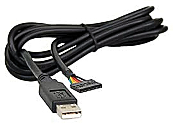
FIGURE 3. FTDI USB to TTL converter cable.
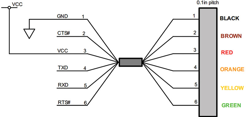
FIGURE 4. FTDI USB to TTL.
There are lots of USB to TTL boards available that use the original FTDI pinout, for instance, the Adafruit FTDI Friend shown in Figure 5. [If you want to get into the details of FTDI converters, you can learn a lot from my book, Virtual Serial Port Cookbook.]
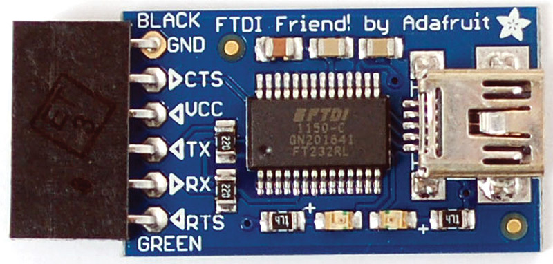
FIGURE 5. Adafruit FTDI Friend.
We can create an FTDI USB to TTL part in Fritzing using the mystery part shown in Figure 6 (creating parts from the mystery part was discussed in Workshop 54). We will use this to provide USB communication and power for our Fritzingduino design.

FIGURE 6. Fritzing FTDI USB to TTL header.
Fritzingduino is Based on BreadboArduino
We will base our Fritzingduino design on the BreadboArduino (discussed in Smiley's Workshop 21). We’ll build this on a large breadboard in Fritzing as shown in Figure 7.
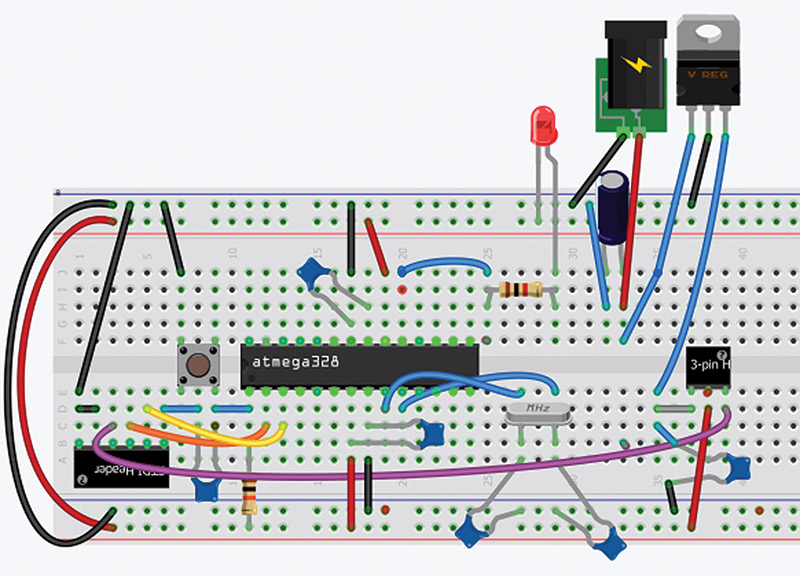
FIGURE 7. Fritzingduino (no shield) breadboard view.
Next, we add the Arduino shield connectors. There are a lot of wires here and the board looks pretty hairy (as you can see in Figure 8).
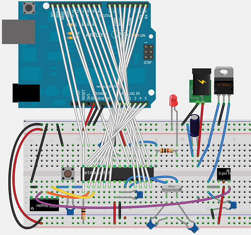
FIGURE 8. Fritzingduino breadboard view.
The figure is a bit deceptive in that it looks like we are adding an Arduino to our board, but the Arduino in the figure actually only adds the shield connectors that we'll need for the schematic and PCB. All those wires hide some of the breadboard, but when you are in the breadboard view in Fritzing you can move the Arduino around and the wires move with it. So, if you can't get at something on the breadboard, you can move the Arduino around until the section of the breadboard you want is accessible.
This board is fairly difficult to wire properly in Fritzing. There were many times I thought I'd made a connection and I hadn't. The schematic shown in Figure 9 also shows this complexity.
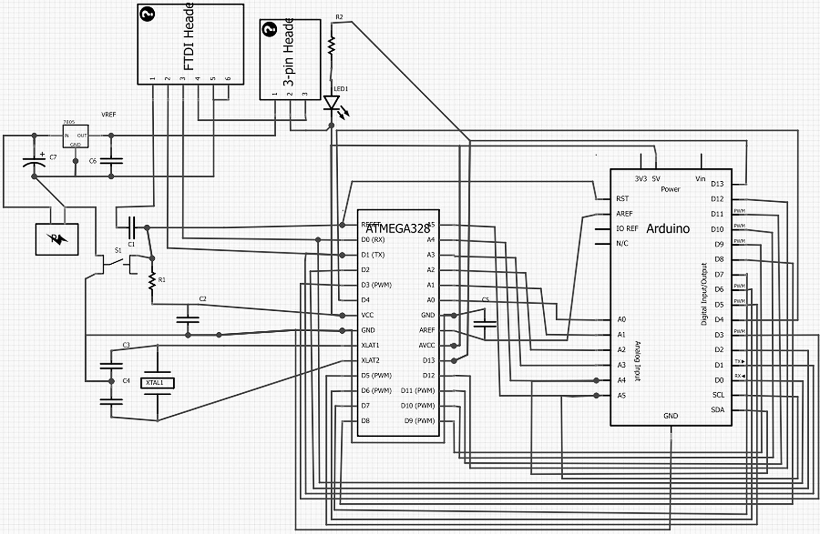
FIGURE 9. Fritzingduino schematic.
You must be very careful to make sure you first understand what every connection is about and that each one is made properly. When you finish, you'll have the PCB design shown back in Figure 1. Just be warned that even if the PCB passes the design rule check, it still doesn't mean you've wired it correctly. DOUBLE-CHECK EACH CONNECTION! This is a pain, but once you've got it right, then you've got the basis for all your future homebrew Arduino projects.
One Minor Problem
One minor problem that might have become a major problem: As you can see from the breadboard view in Figure 8, I used the Arduino UNO to get the shield pins for the PCB layout. I got it all wired up and did the design rule check, and it said the board was ready for production. However, I noticed that the horizontal trace from C3 to C4 to the upper shield GND pin wasn't connected to the rest of the ground traces! What's going on? Is this a bug in Fritzing?
Well, feeling slightly embarrassed, I posted this as a bug on the Fritzing forum and found out immediately (thanks Jonathan Cohen from Fritzing) that the bug was in my wetware, not Fritzing. I was using the Arduino UNO for the shield pins, but the Arduino UNO has the upper and lower shield pin grounds connected on the board. So, if this were a shield design, it would have worked just fine since the grounds would be connected through the Arduino board.
Since it isn't a shield design, it is meant to replace the Arduino in a shield design, so I'm responsible for where each of the shield pins goes. Fortunately, only grounds were a problem and I was able to connect a trace between C3 and the rest of the ground lines. I also had to connect the two lower ground pins together. These two added connections are circled in red in Figure 10.
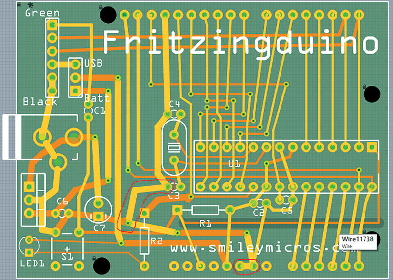
FIGURE 10. Hand routing required.
Just remember to double-check your grounds if you try to repeat my method for getting the UNO shield pins. Next time, we will learn how to put an Arduino bootloader on a raw Atmega328 so that we can finish rolling our own Arduino. Then, we will port the alarm clock circuit to the PCB so that we have a single board that combines an Arduino + shield. NV
| Label |
Part Type |
Properties |
| C1, C2, C3, C4, C5, C6 |
Ceramic Capacitor |
Capacitor 0.1 µF, 100 volt X7R, 10% radial 5.08 mm bulk, Jameco #544884 |
| C7 |
Electrolytic Capacitor |
Capacitor, Radial, 47 µF, 16V, 20%, 85C, 5 x 12 x 5 mm, Jameco #1946244 |
| H1 |
Header - 6 pins 90 degree |
Header, Right Angle Male, 1 row, 6-pin, .1 inch Ctr, .025 inch Pst, .27 inch Gold T10, Jameco #2076851 |
| H2 |
Header - 3 pins Straight |
Header, .1 inch Straight Male, 1 row, 6-pin, .025 inch Pst, .23 inch Goldtail - break for three-pin header, Jameco #153700 |
| J1 |
Shorting block |
Socket, Short Blacks, Black, Close (10), Package of 10 - only need one - Jameco #19141 |
| LED1 |
Red LED - 3 mm |
LED UniColor Red, 697 nm, 2-pin, T-1, Jameco #697565 |
| P1 |
Power plug |
Jack, DC Power, Male, 2.1 mm, Solder, Solder Terminal, Jameco #101178 |
| R1 |
10K Ω Resistor |
Resistor, Carbon Film, 10K ohm, 1/4 watt, 5%, (bag of 10), Jameco #2157167 |
| R2 |
1K Ω Resistor |
Resistor, Carbon Film, 1K ohm, 1/4 watt, 5% (bag of 10), Jameco #2157159 |
| S1 |
Pushbutton |
Single Pole Single Throw Pushbutton Tacticle Switch, Jameco #153251 |
| U1 |
ATMEGA328 |
Eight-Bit with 32 KB Flash Memory Onboard ATMEL AVR Microcontroller (MCU), Jameco #2139111 |
| VREF |
Voltage Regulator - 5V |
Standard Regulator 5V, 1A, 3-pin, (3+Tab), TO-220, Jameco #51262 |
| XTAL1 |
Crystal |
16.000 MHz HC49/S Crystal, Jameco #137891 |
TABLE 1. “Roll Your Own Arduino” Bill of Materials.
Downloads
What’s in the zip?
Fritzingduino Schematic (figure 9)