Sometimes understanding how the simplest of electronic circuits work can be intimidating and/or confusing for the student, hobbyist, or novice. If I remember correctly (back in the 17th century), half of the people in my electronics class dropped out after the first semester. Throw in a course on calculus and you'll witness a raging stampede for the exit door. Who do we blame for this abysmal dropout rate — students, teachers, or curriculum? Andrew Carnegie was once asked, "What's more important: labor, capital, or brains?" His reply was, "What's the most important leg on a three-legged stool?"
Unfortunately, the answer to the blame question is beyond the scope of this article. What should be important is presenting the subject of electronics in such a way that makes it easy for anyone to learn. With that in mind, let’s take a look at one of those simple and ubiquitous circuits: the transistor switch. Don’t worry, there’s nothing more challenging here than multiplication, division, addition, and subtraction. So, let’s begin!
A TRANSISTOR AS A SWITCH
Look at Figure 1. It shows a typical general-purpose (NPN) transistor/LED circuit. If you hook up +5 volts to Vcc in this circuit and pulse the input terminal (Vin) with +5V, 0V, +5V, etc., the LED will flash on and off accordingly. Of course, in order to make this circuit function properly, you have to calculate the correct resistor values for RC and RB. How do you do that? Well, keep reading.
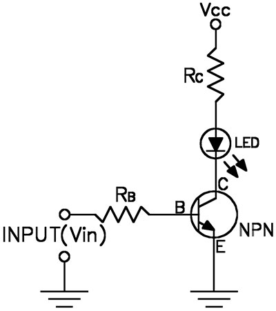
FIGURE 1.
Before we start, it should be noted that we’ll be using the transistor as a simple switch and not as an amplifier. Remember, transistors can operate either as an amplifier or a switch. If you’re using a transistor to amplify a signal, the transistor is said to be operating in the “active” or “linear” region.
Without going too deep into transistor theory, the active region entails a range of operating points (Google “transistor characteristic curves”) at which the transistor will amplify a signal without distortion.
On the other hand, when the transistor is used as a switch, it is operating in what is called the “digital” mode (on/off). In this state of operation, the transistor does not “amplify” the input voltage (VIN) in any way. To use a transistor as a switch, all you have to do is increase the current at the base terminal to a certain level, and the transistor will go into a state commonly known as “saturation.” This is a state (mode of operation) where no matter how much additional current is pumped into the base terminal of the transistor, the collector current will not increase any further.
Once a transistor is in saturation mode, it acts just like a closed SPST mechanical switch (see Figure 2). In turn, when the transistor is turned off (no base current), it goes into “cut-off” mode (fully off). Simply put, the transistor is either on or off — amplification is immaterial.
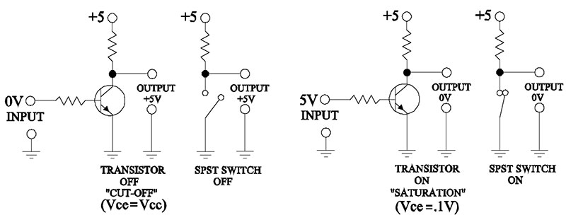
FIGURE 2.
Okay, now that you know the difference between a transistor amplifier and a switch, let’s use the transistor as a switch in order to flash an LED on and off.
CHECK THE DATASHEET
The first step is to Google the datasheets for both the LED and the transistor. You’ll notice on the LED datasheet a listing for the maximum forward current (IF). Most of the popular 5 mm diameter through-hole LEDs have a maximum current rating somewhere around 20 mA.
Once the maximum LED rating is established, what do we do with that information? Well, it means we need to reduce the max rating of 20 mA to a safe current level so the LED isn’t destroyed. A good starting point is somewhere between 5 and 15 mA — depending on how bright of an LED you need. Let’s agree here to set the maximum current (IC(MAX)) flowing through our LED to 15 mA. Now, go ahead and use Ohm’s Law to calculate the value for the collector resistor (Rc). The formula is listed below; assume we have +5V as our power supply (Vcc) and (IC(MAX)) = 15 mA.
RC = VCC = 5
IC(MAX) .015
Did you calculate a value of 333.33 ohms for RC? You are correct! Okay, stop right there — we have a problem! The formula above is missing a couple of very important electrical parameters. What’s missing is the fact that both the LED and transistor — when turned on — have a voltage drop across their terminals and this must be accounted for in the formula.
A general-purpose transistor will drop about .1 to .3 volts across the collector/emitter terminals (VCE(sat); see datasheet) when in saturation mode (fully on). Once a transistor saturates, the collector current reaches a level or plateau where any additional increase in the base current will not cause a further increase in collector current. In “theory,” at this point the collector/emitter voltage drop (VCE(sat)) should be zero if the transistor was working like an SPST mechanical switch.
Remember, a mechanical switch has no voltage drop when flipped to the on state because there’s no resistance between the contacts. On the other hand, transistors have a small amount of resistance across the collector/emitter terminals (RCE) when switched on, and therefore a voltage drop. [The resistance is a result of the PN junction doping process during manufacturing.]
In addition to the transistor voltage drop, the LED will also drop somewhere between 1.2 and 3 volts when it’s switched on (check the datasheet under VF). Therefore, in order to calculate the correct value for resistor Rc, the voltage drop across the collector/emitter (VCE(sat)) and the voltage drop across the LED (V(LED)) must be included in the formula. So, here’s the same Ohm’s Law formula modified to account for all the voltage drops:
Rc = Vcc – V(LED) – VCE(sat)
IC(MAX)
Now, let’s calculate the correct resistance value for resistor Rc. Let Vcc = 5V, V(LED) = 1.9V, VCE(sat) = .1V, and IC(MAX) = 15 mA. The answer is:
Rc = Vcc – V(LED) – VCE(sat)
IC(MAX)
Rc = 5 – 1.9 – .1
.015
Rc = 200 ohms
The calculation shows that we need a 200 ohm resistor for Rc in order to limit the current through the LED to a safe 15 mA. Notice, had we used the basic Ohm’s Law formula (Rc = Vcc / IC(MAX)), RC would be 333.33 ohms. The real problem with using a 333.33 ohm resistor for RC begins when you actually breadboard the circuit, only to find out the current you expected through the LED is not the required 15 mA, but 9.2 mA (a 39% loss). Therefore, if you fail to add both the LED and transistor voltage drops in the calculation, your LED won’t be as bright as expected.
Try and look at the LED and transistor as small resistors. In a series circuit, you would add all the resistor values together to get the total resistance, right? Well, all we’re doing here is accounting for all the voltage drops in a series circuit.
Figure 3 clearly shows what happens to the collector current (IC(MAX)) when you don’t include all the voltage drops in the formula.
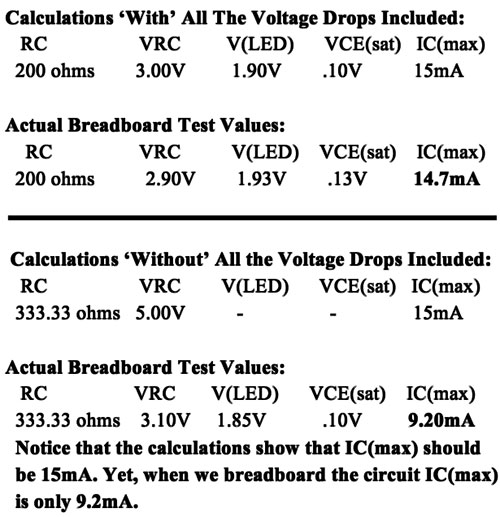
FIGURE 3.
BASE TO CONTROL
The question now is how do you control the transistor so it turns on and off? Well, we have to do two things: 1. Find the correct transistor base current (IB) that will saturate the transistor. 2. Calculate the resistance value for the base resistor RB (see Figure 1). The formula for finding the base current is:
IB(EOS) = IC(MAX)
Beta (min)
Notice here, in order to find the base current (IB), we divide the maximum collector current (IC(MAX)) we want to go through the LED (15 mA) by the minimum Beta listed on the datasheet (hFE). What is Beta? Beta — also known as DC current gain — is a ratio relating to how much current gain you can expect through a transistor’s collector terminal given a certain amount of current going into the base terminal. In other words, the base current controls the collector current. It’s kind of like a small water valve controlling the flow of water running through a large pipe.
Having said all that — and this is very important — Beta (gain) is only used in amplifier design. When you’re using a transistor as a switch (digital mode), Beta has little effect or meaning because the transistor is not operating in the active region that amplifiers work in. Once a transistor switch is in saturation mode, there’s no collector current gain beyond saturation.
In other words, once a transistor switch reaches the saturation point, the gain formula IC = Beta x IB no longer applies because the voltage drop across the collector/emitter terminals (VCE(sat)) has reached its lowest saturation voltage of .1V. When VCE(sat) reaches this voltage level, the collector current can’t increase beyond this point — even if the base current continues to increase.
Remember, a transistor operating in digital mode (on/off) is either in saturation mode (fully switched on) or in cut-off mode (fully switched off). Therefore, any level of collector current (Ic) in between the two states of saturation and cut-off is not important to the functioning of a transistor switch — it’s only important to amplifier designers.
Okay, so what value do we use for Beta in the formula to find the base current (IB)? Well, the standard rule of thumb states that you should use the minimum Beta (hFE) listed on the datasheet. Unfortunately, the minimum Beta listed on the datasheet will only place the transistor at the Edge of Saturation (EOS). Since transistors are sensitive to temperature changes, a change in temperature could force the transistor to move from the EOS into the “active” area (amplifier region).
Therefore, in order to eliminate this possibility, we use what is known as an “Overdrive Factor” (ODF). This is an arbitrary number between 2 and 10 that is used to insure that the transistor is driven hard into saturation (fully turned on) — and where temperature changes fail to drop the transistor out of saturation. Therefore, IB equals:
IB = IB(EOS) x ODF
↓
IB = IC(MAX) x ODF
Beta (min)
IB = .015 x ODF
100
IB = .15 mA x 10
IB = 1.5 mA
Notice, in the formula above, by using an ODF of 10 we increase the base current from 150 µA to 1.5 mA, thereby assuring that the transistor is forced into deep saturation. For example, if a datasheet listed a Beta(min) of 75, and you needed a collector current (IC(MAX)) of 25 mA, IB would be .333 mA (.000333A). Unfortunately, 333 µA would only put the transistor at the EOS. By using an ODF of 10, we increase the base current (IB) to 3.3 mA — well beyond the EOS and into deep saturation.
Now that we have established a base current (IB) of 1.5 mA is required to saturate our transistor, let’s calculate the resistance value needed for the base resistor RB. Once again, we use Ohm’s Law to calculate for RB:
RB = VIN - VBE(sat)
IB
RB = 5 - .6
.0015
RB = 2933.33 ohms
Note in the formula above, that VBE(sat) is the required base voltage that must be present in order to forward-bias the transistor’s base/emitter junction (i.e., to turn the transistor on). Generally speaking, this value is between .6 to .7 volts for a general-purpose transistor. Always check VBE(sat) listed on the datasheet to verify.
Finally, we calculate the voltage drop across RB (VRB) by multiplying the base current (1.5 mA) by the resistance of RB (2.933K). Therefore, VRB = 4.4V.
Figure 4 shows the finished LED circuit with all the components and electrical parameters clearly marked (Ohm’s Law was also used to calculate the resistance for R(LED) and R(CE)).
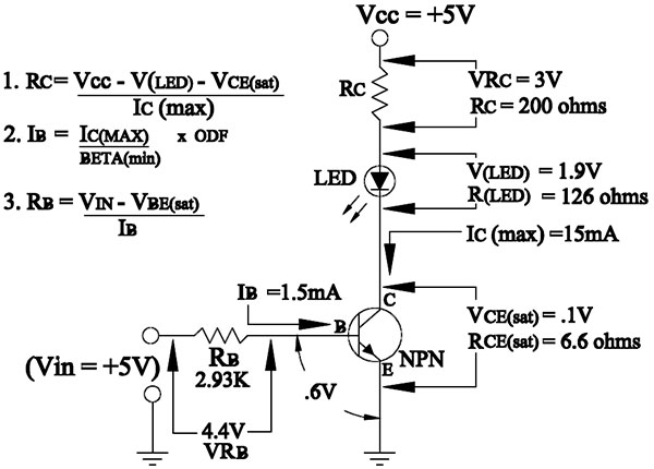
FIGURE 4.
We now have the correct resistor values in order to operate the LED and transistor circuit in a safe manner: Rc = 200 ohms; and RB = 2933.33 ohms.
I’m sure you’ve notice that our 2.933K resistor is not a standard size you can actually purchase anywhere. The rule of thumb in this case states that you can use the next standard resistor value below 2.933K (2.7K to 2.87K). Why?
The lower resistance only helps to decrease the chance of the transistor from falling out of saturation mode during temperature and power supply variations by increasing the base current (i.e., transistor goes even deeper into saturation).
RECAP
Let’s review all the steps required to use a transistor as a switch:
- Download the datasheets for the LED and transistor.
- Determine the max current (IC(MAX)) you want to go through the LED and transistor, and verify that it doesn’t exceed the maximum current rating of the LED (IF) or the transistor (Ic); refer to the datasheet.
- Calculate the value for resistor Rc. Make sure to include the voltage drops for the LED (V(LED)) and the transistor (VCE(sat)) in the Ohm’s Law formula.
- Calculate the transistor’s base current IB using an ODF of 10.
- Calculate the resistance value for base resistor RB.
That’s it. Kind of easy — well, maybe not.
IMPORTANT POINTS
- The circuit designer (you) determines what the correct transistor collector current (IC(sat)) should be by looking at the LED/transistor datasheets and verifying that the current going through the transistor/LED circuit is below the maximum ratings for both devices. In other words, the saturation current (IC(sat)) flowing through a transistor switch is not determined by the transistor's internal electrical parameters, but rather by the external components (resistor/LED) employed by the circuit designer.
- Beta (DC gain) as listed in the datasheet has no meaning when a transistor is used as a switch (saturation/cut-off). Only amplifier designers care about the various levels of collector current (gain) in between saturation and cut-off. In other words, any level of collector current in between the two operating states of "saturation" and "cut-off" (i.e., active region) is not important to the functioning of a transistor switch circuit.
- "Saturation" in a transistor switch circuit is achieved when the voltage across the collector/ emitter (VCE(sat)) is less than or equal to .1 to .3 volts - depending on the type of transistor. At that voltage point, the transistor appears to act like a simple SPST mechanical switch that has been closed (On).
FINAL NOTE
On a personal note, when I breadboard a circuit I only use through-hole, red, 5 mm diameter, ultra-bright, water-clear dome 640 nm LEDs. I’ve tried other LEDs, but the water-clear dome LEDs are the best. They’re so bright, they hurt your eyes — no kidding!
Order a bag of LEDs from Digi-Key, Jameco, or Mouser for your next project — it makes life easier. NV
Switching Options
The transistor switch can be very useful in a variety of circuits. Unfortunately, in some cases, it's not the best solution. For example, if you're building an H-bridge circuit to control the motors on a battery operated robot, you wouldn't use four transistor switches because of the large .7 voltage drop across each of the base/emitter junctions. In this case, a power MOSFET switch would be a better choice — considering the on resistance (RDS) across the drain and source terminals (i.e., voltage drop) of a MOSFET is much lower at saturation than a BJT transistor.
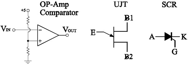
FIGURE A. A few other optional switching devices you can use when a simple transistor switch or MOSFET is not applicable.
Facts about the Transistor Switch
- Any level of collector current (Ic) in between the two states of saturation and cut-off is not important to the design or functioning of a transistor switch — it's only important to amplifier designers.
- When using a transistor as a switch (digital mode), DC Beta (hFE) has no meaning because the transistor is not operating in the active region that amplifiers work in. A transistor switch is either in saturation mode (fully on) or cut-off mode (fully off). In other words, the gain formula Ic = Beta x Ib is invalid beyond the saturation point.
- The saturation current (Ic(sat)) flowing through a transistor switch is not determined by the transistor's internal electrical parameters, but rather by the external components (resistor/LED) employed by the circuit designer.
- To force a transistor switch into deep saturation, the circuit designer adds an overdrive factor to the base current.